Table of Contents
Advertisement
Quick Links
Advertisement
Table of Contents

Related Manuals for Schuchmann rifton dynamic pacer


Summary of Contents for Schuchmann rifton dynamic pacer
- Page 1 dynamic pacer. Instructions for use. dynamic pacer. The dynamic gait trainer.
- Page 2 Instructions for use may deviate from your product due to differing equipment. We reserve the right to make technical modifica- tions. Important information! Ensure that these Instructions for use remain with the product. Your schuchmann Team...
-
Page 3: Table Of Contents
Contents. 1. Preparation................... 05 1.1 Delivery ..........................05 1.2 Safety measures prior to use ................05 1.3 Safe disposal .......................05 1.3.1 Packaging ......................05 1.3.2 Product ........................05 1.4 Where to store the Instructions for use ............05 2. Product description............... 06 2.1 Material information ....................06 2.2 Handling / transport ....................06 2.3 Application areas, use according to the intended purpose .....06 2.3.1 Indication ......................06... - Page 4 Contents. 4.6 Padded armrests ....................... 18 4.7 Padded lower arm supports ................19 4.8 Chest structure ......................20 4.9 Torso support ......................21 4.10 Hip positioning aid ....................22 4.11 Hip positioning pad ....................23 4.10 Function and parking handbrake ..............24 4.13 Pelvis positioning aid ....................
-
Page 5: Preparation
1.4 Where to store the Instructions for use Please store these Instructions for use carefully and ensure that these Inst- ructions for use remain with the product in case of re-use. Should you lose the instructions, you can always download an updated version at www. schuchmann.de . -
Page 6: Product Description
2. Product description. 2.1 Material information Individual parts (nuts, bolts and screws etc.) are galvanised, plated with nickel or made of stainless steel. The padded parts are made of PU foam with a fire-retardant coating made of expanded Vinyl. The frames are made from steel or aluminium with a stove-enamel finish. -
Page 7: Use Not In Accordance With The Intended Purpose / Warning Gui
2. Product description. 2.4 Use not in accordance with the intended purpose / warning guidelines • Ensure that the gait trainer is stored in a dry place. • Ensure that the gait trainer is only used by one user. • Correct usage of the product requires precise and careful training of the accompanying person. -
Page 8: Equipment For Basic Model
2. Product description. 2.5 Equipment for basic model 2.5.1 pacer. (Size 0 mini) • One-part base frame with handle frame, four 5 ½ casters (see point 3.3) with friction brake, backwards stop, parking brake and direction lock. 2.5.2 dynamic pacer. (Size 1 - 4) •... -
Page 9: Product Overview
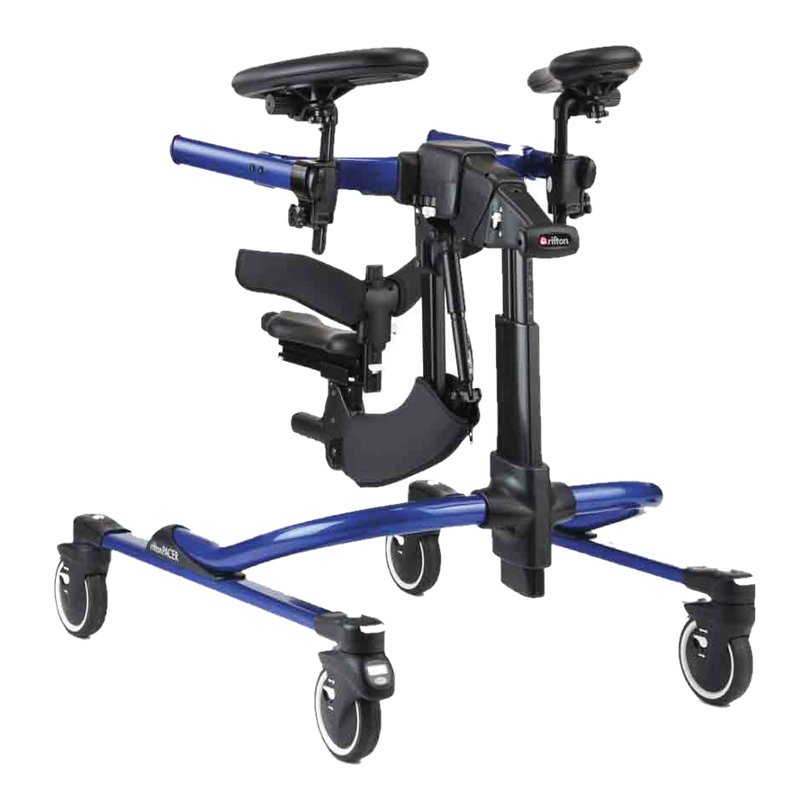
2. Product description. 2.7 Product overview The Fig. below is intended to show you the designation of the most important components as well as the terms which you will find in these Instructions for use. 2.7.1 pacer. (Size 0 mini) Hand rims Padded torso support Base frame... -
Page 10: Settings
3. Settings. Settings and adjustments to the product or accessories may only be made by people who have been given the necessary instructions by a medical product advisor. Please ensure that none of the user's extremities are in the respective area when making adjustments of any kind to minimise the risk of injury. -
Page 11: Dynamic Top Frame
3. Settings. 3.1.2 Dynamic top frame The dynamic top frame can be adjusted in height - to do this, press the button (A). In addition, this provides dynamic support (vertical and horizontal). In order to activate/deactivate the vertical dynamic support (B), lift the top frame up slightly and press the switch (C) –... -
Page 12: Sub-Frames
3. Settings. 3.2 Sub-frames 3.2.1 Standard sub-frame The standard sub-frame (A) is equipped with four 5 ½" castors. Every castor (B) is equipped with a parking brake, a friction brake, a back- wards stop and a direction lock (see Point 3.3). Optionally, the sub-frame is also available with a distance measurement system (see Point 4.1). -
Page 13: Castors / Wheels
3. Settings. 3.3 Castors / wheels The 5 ½“ casters (A) on the standard and treadmill sub-frame and the pacer. Each size 0 mini is equipped with a parking brake, a friction brake, a backwards stop and a di- rection lock. The combination sub-frame is equipped with two 8"... -
Page 14: Accessories
4. Accessories. 4.1 Distance measurement system The distance measurement system (A) shows the distance covered. To reset the distance measurement system to "0", press the reset button (B). In order to display the entire distance cover- ed, press the reset button (B) for one second. -
Page 15: Push Handles
4. Accessories. 4.3 Push handles The push handles (A) have recesses (B) so that the hip positioning aid or the pelvic positioning aid can be hooked in using rings (see Points 4.9 and 4.12). The push handles (A) can also be used for the accompanying person, for example to push the user slightly. -
Page 16: Grip Rings
4. Accessories. 4.4 Grip rings If the dynamic pacer is used as an anterior gait trainer, it is recommended to mount the grip rings (A) in front of the cross strut (B) of the top frame (C). This creates stable positi- oning and leaves sufficient space for further accessories. -
Page 17: Handles
4. Accessories. 4.5 Handles If the dynamic pacer is used as an anterior gait trainer, it is recommended to mount the handles (A) in front of the cross strut (B) of the top frame (C). This creates stable positioning and leaves sufficient space for further ac- cessories. -
Page 18: Padded Armrests
4. Accessories. 4.6 Padded armrests If the dynamic pacer is used as an anterior gait trainer, it is recommended that the armrests (A) are mounted in front of the cross strut (B) of the top frame. This creates stable positioning and leaves sufficient space for further ac- cessories. -
Page 19: Padded Lower Arm Supports
4. Accessories. 4.7 Padded lower arm supports When the dynamic pacer is used as an an- terior gait trainer, it is recommended that you mount the arm supports (A) in front of the cross strut (B) of the top frame. This creates stable positioning... -
Page 20: Chest Structure
4. Accessories. 4.8 Chest structure Mount the chest structure (A) directly behind the oval crossbar on the top frame and/or the base frame. There is a rear strap (B) at- tached to the back of the chest structure (A); these can be opened and closed easily by means of plug locks (C) on both sides. -
Page 21: Torso Support
4. Accessories. 4.9 Torso support Mount the torso support (A) directly behind the oval crossbar on the top frame and/or the base frame. A safety loop is mounted on the front side of the torso support (A). The torso support can simply be opened and clo- sed through plug locks (D). -
Page 22: Hip Positioning Aid
4. Accessories. 4.10 Hip positioning aid The hip positioning aid (A) helps people to walk tilted forwards. ´To attach the hip positioning aid (A): • Push the loops (B) into the required position on the top frame and/or the base frame. •... -
Page 23: Hip Positioning Pad
4. Accessories. 4.11 Hip positioning pad The hip positioning pad (A) is mounted to the hip positioning aid (B). To do this, please follow the steps below: 1. Pull the rear straps of the hip positioning aid (B) through the crossed straps (C) on the hip positioning pad. -
Page 24: Function And Parking Handbrake
4. Accessories. 4.10 Function and parking handbrake (only on the combination sub-frame) Attachment to the sub-frame 1. Clip the round end of the brake cable (A) into the bracket on the base frame (B). 2. Pull the cable housing (C) forwards and down, then clamp it into the rear end of the bracket. -
Page 25: Pelvis Positioning Aid
4. Accessories. 4.13 Pelvis positioning aid The pelvic positioning aid (A) provides an al- ternative to the hip positioning aid (see Point 4.10) and absorbs part of the user's weight. To attach the pelvis positioning aid (A): • Push the loops (B) into the required position on the top frame and/or the base frame. -
Page 26: Thigh Positioning Aid
4. Accessories. 4.14 Thigh positioning aid We recommend that you mount the upper thigh positioning aid (A) behind the torso support on the top frame or base frame. The adapter clamps (B) of the upper thigh posi- tioning aid (A) differ in external appearance to the adapter clamps (see Point 4.2) of the other accessory parts, but actually function in the same way. -
Page 27: Ankle Positioning Aids
4. Accessories. 4.15 Ankle positioning aids • Combination sub-frame: Insert the end (A) of the rod (1) into the hole on the rear wheel (B). Then pull back the white bar (C) and insert it into the recess (D) on the underside of the sub-frame. -
Page 28: Therapy Table
4. Accessories. 4.16 Therapy table The therapy table (A) is mounted with the aid of an adapter clamp (B) onto the top frame (C) of the dynamic pacer. and/or the base frame of the pacer. (Size 0 mini) attached (see Point 2.7.1). In order to change the position of the therapy table (A): •... -
Page 29: Multi-Positioning Saddle (Mps)
4. Accessories. 4.17 Multi-positioning saddle (MPS) (only for the dynamic pacer. Size 1 - 4) Assembly/removal for size 1 • To mount the small MPS on the top frame, insert the MPS into the recess on the un- derside of the top frame (A). •... - Page 30 4. Accessories. removed using the hook and eye fastener. In order to release the strap completely, press the little white button which is loca- ted under the pad and remove the strap rings from the mount. Tip: Every white button or lever features a setting/adjustment option! Ensure that no extremities are located in the setting or adjustment area!
-
Page 31: Push Bar For Escorts
4. Accessories. 4.18 Push bar for escorts The push bar (A) can be attached to the left and also the right next to the support of the top frame (B) on the sub-frame of the dynamic pacer. The push bar (A) is attached using an adapter clamp (C) that is affixed via the quick release (D). -
Page 32: Use
5. Use. 5.1 As anterior gait trainer Orientated to the front The figures show normal positioning. Plea- se observe that the torso support does not tilt and the hip positioning aid or pelvic positioning aid is mounted behind the user's shoulder area. - Page 33 5. Use. Leaned forwards The figure shows that the user is tilted further forwards than in the standard po- sition. Here please observe the angle of the torso support and that the hip posi- tioning aid is mounted behind the shoul- der area of the user.
-
Page 34: As Posterior Gait Trainer
5. Use. 5.2 As posterior gait trainer The user can be positioned in the gait trainer so that they face in the direction of the open frame. This allows freedom of movement. The torso support can, if used, be opened at the front and back (see Point 4.9). -
Page 35: Cleaning And Maintaining
(such as A + B) on the respective element. Please also pay attention to our general cleaning and Obermaterial/ hygiene advice. This can be found at top cloth/dessus: www.schuchmann.de/mediathek. 100% Polyurethan/ Polyurethane/ Polyuréthane 6.1.2 Disinfection Various products can be used for surface disinfection of metal and plastic parts. -
Page 36: Maintenance Specifications
6. Cleaning and maintaining. 6.3.1 Maintenance specifications • Basic cleaning according to the manufacturer's specifications • Disinfect according to the manufacturer's specifications as required • Damages to the frame, mounting parts and accessories (cracks, breaks, corrosion, bent or missing parts) •... -
Page 37: Spare Parts
6. Cleaning and maintaining. 6.3 Spare parts Use only original accessories and original spare parts from Schuchmann, as otherwise the safety of the user is endangered and the warranty expires. To order spare parts, please contact the supplying specialist dealer (see Point 9.5). -
Page 38: Technical Data
7. Technical data. 7.1 Dimensions Size 0 Size 1 Size 2 Size 3 Size 4 mini Recommended elbow height 39–52 cm 47-70 cm 61 - 89 cm 81-119 cm 86-124 cm Standard sub-frame 52 cm 58 cm 66 cm 71 cm 80 cm Combination sub-frame 76 cm... -
Page 39: Guarantee
8. Guarantee. The two-year statutory guarantee period shall apply for all products. This begins with the delivery or handover of the goods. Should a verifiable material or manufacturing fault occur within this time period, we shall, after carriage paid return to us, view the indicated damage and, if applicable, either repair or deliver a new product at our discretion. -
Page 40: Identification
EU Konformitätserklärung EU Declaration of Conformity Firma / Company Schuchmann GmbH & Co. KG Rudolf-Runge-Str. 3 · 49143 Bissendorf · Deutschland / Germany Tel. +49 (0) 5402 / 40 71 00 · Fax +49 (0) 5402 / 40 71 109 erklärt in alleiniger Verantwortung, dass das nachfolgend genannte Produkt der Risikoklasse 1... -
Page 41: Serial Number / Date Of Manufacture
Date of manufacture Barcode UDI-DI Barcode UDI-PI schuchmann.de • info@schuchmann.de • Fon +49 (0) 5402 / 40 71 00 Product labelling in accordance with MDR 9.3 Product version The gait trainer is available in five sizes and can be supplemented through a diverse range of accessories (see Point 4). - Page 42 Notes.
- Page 43 Notes.
- Page 44 schuchmann.de...
Need help?
Do you have a question about the rifton dynamic pacer and is the answer not in the manual?
Questions and answers