Table of Contents
Advertisement
Quick Links
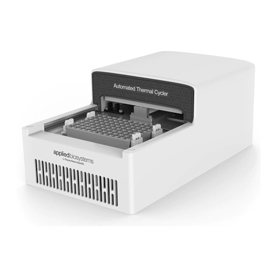
Automated Thermal Cycler (ATC) System
USER GUIDE
Installation, use, and maintenance
Catalog Numbers A30207, A30208, A31486, A31487, A31488, A31489, A31490, A31491, A33976,
A33977, A33978, A33979, A33980, A33981, and A33982
Publication Number MAN0014558
Revision B.0
For Research Use Only. Not for use in diagnostic procedures.
Advertisement
Table of Contents

Related Manuals for Applied Biosystems A30207


Summary of Contents for Applied Biosystems A30207
- Page 1 Automated Thermal Cycler (ATC) System USER GUIDE Installation, use, and maintenance Catalog Numbers A30207, A30208, A31486, A31487, A31488, A31489, A31490, A31491, A33976, A33977, A33978, A33979, A33980, A33981, and A33982 Publication Number MAN0014558 Revision B.0 For Research Use Only. Not for use in diagnostic procedures.
- Page 2 Life Technologies Holdings Pte Ltd | Block 33 | Marsiling Industrial Estate Road 3 | #07-06, Singapore 739256 For descriptions of symbols on product labels or product documents, go to thermofisher.com/symbols-definition. The information in this guide is subject to change without notice. DISCLAIMER: TO THE EXTENT ALLOWED BY LAW, THERMO FISHER SCIENTIFIC INC.
-
Page 3: Table Of Contents
Contents ■ CHAPTER 1 About the Automated Thermal Cycler (ATC) System ... . . 6 Package contents ............. . . 6 Setup options . - Page 4 Contents ■ CHAPTER 4 Maintain the Automated Thermal Cycler (ATC) System ..32 Clean the instrument ............32 Preparation .
- Page 5 Contents StopProtocol ............. . 55 SubScribe .
-
Page 6: Chapter 1 About The Automated Thermal Cycler (Atc) System
(OEM) for use in automation workflows. The Automated Thermal Cycler (ATC) System can also be used as a stand-alone device in conjunction with a third-party ™ desktop software. It is also compatible with the Applied Biosystems Thermal Cycler Fleet Control Software. -
Page 7: Setup Options
Chapter 1 About the Automated Thermal Cycler (ATC) System Setup options The ATC Control Module box contains: • ATC Control Module Setup options The system can be set up in two ways. Table 2 Automated Thermal Cycler (ATC) System configurations Setup option image Within a Robotic environment... -
Page 8: Environmental Requirements
Chapter 1 About the Automated Thermal Cycler (ATC) System Environmental requirements Environmental requirements Temperature and humidity requirements Ensure that the installation site is maintained under the following conditions: Table 3 Temperature and humidity requirements Condition Acceptable range Temperature 15 to 30°C (59 to 86°F) Humidity 15 to 80% relative humidity, non-condensing Avoid placing the instrument adjacent to heaters, cooling ducts, or in direct sunlight. -
Page 9: System Specifications
Chapter 1 About the Automated Thermal Cycler (ATC) System System specifications Automated Thermal Cycler (ATC) System technical specifications: (continued) Table 4 Feature Specification • • Height: 133.6 mm (5.3 in) Height: 76.4 mm (3.0 in) — Dimensions (including rubber feet) •... -
Page 10: Location Of Power Points And Ports
Chapter 1 About the Automated Thermal Cycler (ATC) System Location of power points and ports Location of power points and ports Figure 1 Back panel of the ATC control module Power port Power button Ethernet port Automated Thermal Cycler (ATC) System DSUB USB port Figure 2 Back panel of the ATC block module Automated Thermal Cycler (ATC) System DSUB... -
Page 11: Use Atc Plate Adaptors
Chapter 1 About the Automated Thermal Cycler (ATC) System Use ATC plate adaptors Use ATC plate adaptors The plate adaptor helps to ensure that the supported consumables (full skirt and semi-skirt plates) are ejected properly, and that the temperature is kept uniform. The Automated Thermal Cycler comes factory configured with a full-skirted adaptor (amber color) already installed. - Page 12 Chapter 1 About the Automated Thermal Cycler (ATC) System Use ATC plate adaptors Figure 4 Uninstall the full-skirted plate adaptor Slightly push the tabs highlighted in red. Grab the bottom of the adaptor, and tilt up. Remove the adaptor. • To install full-skirted plate adaptor follow the instructions in Figure 5. Automated Thermal Cycler (ATC) System User Guide...
- Page 13 Chapter 1 About the Automated Thermal Cycler (ATC) System Use ATC plate adaptors Figure 5 Install full-skirted plate adaptor Remove half skirted adaptor, if any. place full skirted adaptor by tilting an angle allowing the front to insert under the frame. Push the two tabs allowing it to be inserted into the frame.
- Page 14 Chapter 1 About the Automated Thermal Cycler (ATC) System Use ATC plate adaptors Figure 6 Installation of semi-skirted plate adaptors and ejector buttons Slot the semi-skirted plate adaptor to the gap between the Alu top plate and drip pan. Slot in the adaptor and center it. Snap fit the ejector buttons.
-
Page 15: Chapter 2 Operate The Automated Thermal Cycler (Atc) System As
Operate the Automated Thermal Cycler (ATC) System as a stand- alone system ■ Connect the hardware ..............15 ■... - Page 16 Chapter 2 Operate the Automated Thermal Cycler (ATC) System as a stand-alone system Operate ATC as stand alone using computer 2. Once the software is installed, click on the ATC Demo icon to launch the software. Figure 7 Desktop icon of ATC Demo software Figure 8 ATC Demo software initial screen Discover A pop up window...
- Page 17 Chapter 2 Operate the Automated Thermal Cycler (ATC) System as a stand-alone system Operate ATC as stand alone using computer 6. Click Connect. Figure 9 ATC Demo software connected to the ATC instrument 7. Hover mouse over the real time monitoring temperature curves to see black window legend with graph related information.
-
Page 18: Program And Execute A Run On The Atc
Chapter 2 Operate the Automated Thermal Cycler (ATC) System as a stand-alone system Program and execute a run on the ATC Program and execute a run on the ATC Figure 10 Run Protocol Add (+), Remove (−) stages Remove and arrange order Run Mode drop down Cover Temperature and Sample Volume Temperature, Ramp Rate, Hold Time... - Page 19 Chapter 2 Operate the Automated Thermal Cycler (ATC) System as a stand-alone system Program and execute a run on the ATC 6. Press Load to display previously protocols. Note: An empty protocol cannot be saved. 7. Click Export SiLA to export protocol for integration with SiLA based software or scheduler. Note: Although SiLA exported protocol is an .xml file it should opened using a text editor in order to see the content, otherwise they might appear empty if opened with a default browser application.
- Page 20 Chapter 2 Operate the Automated Thermal Cycler (ATC) System as a stand-alone system Program and execute a run on the ATC Note: A message will notify the user if the Protocol Editor is started while the instrument is already running (Edit Only mode). User can still edit and export a protocol while the software control and monitor the instrument running, without interfering with the current run.
- Page 21 Chapter 2 Operate the Automated Thermal Cycler (ATC) System as a stand-alone system Program and execute a run on the ATC A run in progress will show the following display: Figure 13 ATC Demo software −Run in progress monitoring If the lid is opened while a run is in progress a warning message will open. Figure 14 Alert of run in progress Automated Thermal Cycler (ATC) System User Guide...
-
Page 22: Connect To Multiple Instruments Using The Desktop Software
Chapter 2 Operate the Automated Thermal Cycler (ATC) System as a stand-alone system Connect to multiple instruments using the desktop software 8. Click Abort to end the run. Figure 15 Run ended notification Connect to multiple instruments using the desktop software 1. -
Page 23: Firmware Upgrades
Chapter 2 Operate the Automated Thermal Cycler (ATC) System as a stand-alone system Firmware upgrades 4. Click Discover in each specific application window to identify the instrument that you want to connect to. Figure 16 Parallel ATC instruments control and monitoring through multiple instances of ATC Demo software Note: We recommend that you use one computer to control multiple ATC instruments, and we do not recommend that a single ATC is connected to multiple computers. - Page 24 Chapter 2 Operate the Automated Thermal Cycler (ATC) System as a stand-alone system Firmware upgrades 4. A window will pop-up with the available firmware versions for upgrade. Double click the version you want to initiate the upgrade. 5. Firmware upgrade will initialize, and should take 2−3 minutes to complete. Automated Thermal Cycler (ATC) System User Guide...
- Page 25 Chapter 2 Operate the Automated Thermal Cycler (ATC) System as a stand-alone system Firmware upgrades 6. When the firmware update has completed, press OK. The computer will be disconnected from the instrument. Wait 2−3 minutes for instrument to re-initialize and then you can connect to the instrument again.
-
Page 26: Chapter 3 Operate The Automated Thermal Cycler (Atc) System As
Operate the Automated Thermal Cycler (ATC) System as part of a robotic system ■ Set up the Automated Thermal Cycler (ATC) System on a robotic system ....26 ■... - Page 27 Chapter 3 Operate the Automated Thermal Cycler (ATC) System as part of a robotic system Set up the Automated Thermal Cycler (ATC) System on a robotic system 6. Identify the IP address of the Automated Thermal Cycler (ATC) System device. If needed, use the ATC demo software to discover the instrument and collect the IP address.
-
Page 28: Guidelines For Robotic Configurations
Chapter 3 Operate the Automated Thermal Cycler (ATC) System as part of a robotic system Connect Automated Thermal Cycler to a robotic system Guidelines for robotic configurations • Stack the thermal block and the control box using a rack or place sideways with no clearance between the side panels. - Page 29 Chapter 3 Operate the Automated Thermal Cycler (ATC) System as part of a robotic system Perform a thermal protocol run Created By : Thermofisher Scientific Date : 23-02-2016 Reset(*requestId [RequestID] , *lockId [LockID], *deviceId "1",*eventReceiverURI [EventRcvURI], *PMSId "SiLATestServer", *errorHandlingTimeout "PT10S", simulationMode false); Initialize(*requestId [RequestID] , *lockId [LockID]);...
-
Page 30: (Optional) View The Progress Of The Thermal Protocol Run
Chapter 3 Operate the Automated Thermal Cycler (ATC) System as part of a robotic system Perform a thermal protocol run 3. Edit the following fields to create a custom protocol: • Protocol name • Sample volume • Stage label Note: A stage is made of several steps and can be iterated. You cannot iterate steps but you can add a number of steps to a stage. -
Page 31: (Optional) Abort The Thermal Protocol Run
Chapter 3 Operate the Automated Thermal Cycler (ATC) System as part of a robotic system Perform a thermal protocol run • Stop viewing the progress of the thermal protocol by unsubscribing to two main topics. – UnSubScribe(*requestId [RequestID], *lockId [LockID], *Event "Run"); –... -
Page 32: Chapter 4 Maintain The Automated Thermal Cycler (Atc) System
Maintain the Automated Thermal Cycler (ATC) System ■ Clean the instrument ..............32 ■... -
Page 33: Decontaminate The Sample Wells
Chapter 4 Maintain the Automated Thermal Cycler (ATC) System Clean the instrument To clean the sample wells: 1. Follow the steps in “Preparation” on page 2. Remove the sample tray from the sample block and set it aside. 3. Use a cotton swab soaked in isopropanol to clean the sample wells thoroughly. Make certain that the isopropanol has evaporated completely before reloading a sample tray. -
Page 34: Clean The Heated Cover
Chapter 4 Maintain the Automated Thermal Cycler (ATC) System Replace the fuses Clean the heated cover Ensure that you have dismounted the heated cover from the Automated Thermal Cycler (ATC) System before cleaning. See “Separate the heated cover from the block” on page 35for instructions. -
Page 35: Separate The Heated Cover From The Block
Chapter 4 Maintain the Automated Thermal Cycler (ATC) System Separate the heated cover from the block 3. Remove each fuse from its fuse holder and inspect it for damage. Carbon typically coats the inside of failed fuses. Good Failed 4. Replace each failed fuse. Note: Use two of the Listed and Certified fuses 10A Type Time-Lag 250Vac 5x20 mm. - Page 36 Chapter 4 Maintain the Automated Thermal Cycler (ATC) System Separate the heated cover from the block 2. Remove the two white rubber screw caps with a tweezer or screwdriver. 3. Remove the two M3 x 6 socket head cap screws located at the top of the block with a Hex/Allen key.
- Page 37 Chapter 4 Maintain the Automated Thermal Cycler (ATC) System Separate the heated cover from the block 5. Remove the two jack screws located at the rear of the block with a 5 mm or equivalent hexagon socket driver, then using a slotted screwdriver in the clockwise direction, open the heated cover. OPEN Manually overrisde the headed cover...
- Page 38 Chapter 4 Maintain the Automated Thermal Cycler (ATC) System Separate the heated cover from the block 9. Position the Automated Thermal Cycler (ATC) System as shown in the following image to remove the six M3 x 10 socket head cap screws with a Hex/ Allen key. Note: The tightening torque is 8.00 kgfcm (+/- 10%).
- Page 39 Chapter 4 Maintain the Automated Thermal Cycler (ATC) System Separate the heated cover from the block Front closing sensor connector Back opening sensor connector mMor connector Auto Module Base Module Automated Thermal Cycler (ATC) System User Guide...
-
Page 40: Appendix A Parts And Materials
Parts and materials ■ Accessories ............... . . 40 Accessories Unless otherwise indicated, all materials are available through thermofisher.com. -
Page 41: Appendix B Command Dictionaries
Command dictionaries ■ Command directory overview ............41 ■... -
Page 42: Mandatory Commands
Appendix B Command dictionaries Mandatory commands GetConfiguration SetConfiguration LockDevice Pause Reset UnlockDevice Mandatory commands This section describes the mandatory commands available for the SiLA consumer while working with the Automated Thermal Cycler (ATC) System SiLA Provider. All mandatory commands are primarily processed internally by the SiLA State Machine. -
Page 43: Getdeviceidentification
Appendix B Command dictionaries Mandatory commands Device.DoContinue ( *requestId , *lockId requestId lockId Name Type Nullable In/Out false [requestId] String true [lockId] Example: Device.DoContinue(*requestId [RequestID], *lockId [LockID]); GetDeviceIdentification This command provides a basic fingerprint of the plugin in use. As this command is synchronous, its return value is provided by the out parameter deviceDescription. -
Page 44: Getstatus
Appendix B Command dictionaries Mandatory commands GetStatus This command returns the current status of the SiLA state machine. For further details, refer to the SiLA command dictionary. Device.GetStatus ( *requestId , *deviceIdout , *stateout, *lockedout , requestId *PMSIdout , *currentTimeout ) Name Type Nullable... -
Page 45: Pause
Appendix B Command dictionaries Mandatory commands Device.LockDevice ( *requestId , *lockId , *lockTimeout requestId lockId "PT100S",*eventReceiverURI [EventRcvURI ], *PMSId "SiLATestSuite") Name Type Nullable In/Out false [ requestId] String false [ lockId] Duration true [lockTimeout] String true [eventReceiverURI String true [PMSId] Example: Device.LockDevice(*requestId [RequestID], *lockId [LockID], *lockTimeout "PT100S",*eventReceiverURI [EventRcvURI ], *PMSId "SiLATestSuite") -
Page 46: Unlockdevice
Appendix B Command dictionaries Required Commands for PCR Cyclers (continued) Name Type Nullable In/Out String false [PMSId] Duration True [errorHandlingTimeou Boolean True [simulationMode] Example: Device.Reset(*requestId [RequestID], *lockId [LockID], *deviceId "1",*eventReceiverURI [EventRcvURI], *PMSId "SiLATestSuite", *errorHandlingTimeout"PT10S", *simulationMode false) UnlockDevice This command is allowed only in the state, "standby". It unlocks the usage of the SiLA Provider for the specified lockId. -
Page 47: Getparameters
Appendix B Command dictionaries Required Commands for PCR Cyclers Example: Device.Delay(*requestId [RequestID], *lockId [LockID], *duration "PT5S") GetParameters This commands requests the current parameter settings from the device, which in case of the Automated Thermal Cycler (ATC) System is the name and the definition of the currently running protocol. -
Page 48: Prepareforoutput
Appendix B Command dictionaries Required Commands for PCR Cyclers Example: Device.PrepareForInput(*requestId[RequestID], *lockId[LockID]); PrepareForOutput This command opens the lid. Device.PrepareForOutput ( *requestId , *lockId requestId lockId Name Type Nullable In/Out false [requestId] String true [lockId] Example: Device.PrepareForOutput(*requestId[RequestID], *lockId[LockID]); SetParameters This command defines the specified protocol on the Automated Thermal Cycler (ATC) System. The ProtocolName from within the protocol definition is used to select the protocol for execution by the ExecuteProtocol command. -
Page 49: Optional Commands For Pcr Cyclers
Appendix B Command dictionaries Optional commands for PCR Cyclers <Temperature>95.0</Temperature> <Temperature>95.0</Temperature> <Temperature>95.0</Temperature> </Ramp> <Hold HoldTime=\"20\"/> </Step> <Step Identifier=\"2\"> <Ramp Rate=\"90\"> <Temperature>60.0</Temperature> <Temperature>60.0</Temperature> <Temperature>60.0</Temperature> </Ramp> <Hold HoldTime=\"20.0\"/> </Step> </Stage> </Protocol> "); Optional commands for PCR Cyclers GetConfiguration This command gets the configuration information about the Automated Thermal Cycler (ATC) System. Device.GetConfiguration ( *requestId , *lockId , *configLevel1,... -
Page 50: Setconfiguration
Appendix B Command dictionaries Optional commands for PCR Cyclers <String>debian</String> </Parameter> <Parameter name="SerialNumber" parameterType="String"> <String>No serial number has been configured on this instrument</String> </Parameter> <Parameter name="SubSystems" parameterType="String"> <String>TBC:Board1,TBC:Board2,TBC:Board3,TBC:Board4,Automation</String> </Parameter> <Parameter name="Version" parameterType="String"> <String>0.1.0</String> </Parameter> <Parameter name="Ready" parameterType="String"> <String>True</String> </Parameter> <Parameter name="MacAddress" parameterType="String"> <String>00:0c:29:01:24:f3</String>... -
Page 51: Optional Commands For Other Device Classes
Appendix B Command dictionaries Optional commands for other device classes <Parameter ParameterType=\"string\" name=\"Nickname\"><string>Nick</string></ Parameter> <Parameter ParameterType=\"Int32\" name=\"Time\"><Int32>1446043300</Int32></ Parameter> </ParameterSet "); Optional commands for other device classes OpenDoor This command opens the lid. Device.OpenDoor ( *requestId , *lockId requestId lockId Name Type Nullable In/Out... -
Page 52: Specific Commands
Appendix B Command dictionaries Specific commands Specific commands ExecuteProtocol This commands aborts execution of any command currently being executed, including a running protocol, and all queued asynchronous commands. ExecuteProtocol ( *requestId , *lockId , *SampleVolume 10 , requestId lockId *RunMode "" , *CoverTemperature 105 , *Delay 0 , *Protocol "MyRunProtocol" , *RunTitle "MyRun"... -
Page 53: Getprotocoldefinition
Appendix B Command dictionaries Specific commands Example: Device.GetDeviceDetails( *requestId[RequestID],*lockId[LockID]) Response Data: <?xml version="1.0" encoding="utf-8"?> <ResponseData xmlns:xsi="http://www.w3.org/2001/XMLSchema-instance" xsi:noNamespaceSchemaLocation="http://sila.coop//schemata/ ResponseType_1.2.xsd"> <ParameterSet> <Parameter name="Door" parameterType="String"> <String>Open</String> </Parameter> <Parameter name="InstrumentState" parameterType="String"> <String>Idle</String> </Parameter> </ParameterSet> </ResponseData> GetProtocolDefinition This command returns the XML representation of the protocol definition of the specified protocol. If no protocol with that name is defined on the device then, depending on the parameter type, all parameters in the returned XML will be empty or 0. -
Page 54: Getprotocoldetails
Appendix B Command dictionaries Specific commands </ParameterSet> </ResponseData> GetProtocolDetails This command returns detailed information about the specified protocol like protocol time, remaining time, and runmode. If no protocol with that name is defined on the device then, depending on the parameter type, all the parameters in the returned XML will be empty or 0. -
Page 55: Stopprotocol
Appendix B Command dictionaries Specific commands </ParameterSet> </ResponseData> StopProtocol This command stops the current Running Protocol. Device.StopProtocol ( *requestId , *lockId , *RunTitle"MyRun" ) requestId lockId Name Type Nullable In/Out false [requestId] String true [lockId] String false [RunTitle] Example: Device.StopProtocol(*requestId[RequestID], *lockId[LockID], *RunTitle"MyRun") SubScribe This command subscribes the events that need to be monitored. -
Page 56: Sila Return Codes
Appendix B Command dictionaries SiLA return codes Device.UnSubScribe ( *requestId , *lockId requestId lockId Name Type Nullable In/Out false [requestId] String true [lockId] String false [Event] Example: Device.UnSubScribe(*requestId[RequestID], *lockId[LockID], *Event"Run") Device.UnSubScribe(*requestId[RequestID], *lockId[LockID], *Event"Temperature") Device.UnSubScribe(*requestId[RequestID], *lockId[LockID], *Event"Error") Device.UnSubScribe(*requestId[RequestID], *lockId[LockID], *Event"Time") SiLA return codes If applicable, the standard SiLA Return Codes are used to indicate successful or faulty command execution. -
Page 57: Appendix C About The Thermal Cycler Fleet Control Software
PCR instruments through a single user interface. The software ™ is compatible with all Applied Biosystems Thermal Cyclers. The Thermal Cycler Fleet Control Software can be purchased separately, and is not included with the Automated Thermal Cycler (ATC) System. For more information visit thermofisher.com. -
Page 58: Appendix D Safety
Safety ■ Symbols on this instrument ............58 ■... - Page 59 Appendix D Safety Symbols on this instrument (continued) Symbol English Français Moving parts Parties mobiles Caution, hot surface Attention, surface chaude On (marche) Off (arrêt) Protective conductor terminal (main ground) Borne de conducteur de protection (mise à la terre principale) Do not dispose of this product in unsorted Ne pas éliminer ce produit avec les déchets municipal waste...
-
Page 60: Conformity Symbols
Appendix D Safety Safety alerts on this instrument Conformity symbols Conformity mark Description Indicates conformity with safety requirements for US and Canada. Indicates conformity with European Union requirements for safety, electromagnetic compatibility and RoHS. Indicates conformity with Australia standard for electromagnetic compatibility. - Page 61 Appendix D Safety Safety alerts on this instrument Automated Thermal Cycler (ATC) System User Guide...
-
Page 62: Safety Information For Instruments Not Manufactured By Thermo Fisher Scientific
Appendix D Safety Safety information for instruments not manufactured by Thermo Fisher Scientific Safety information for instruments not manufactured by Thermo Fisher Scientific Some of the accessories provided as part of the instrument system are not designed or built by Thermo Fisher Scientific. -
Page 63: Electrical Safety
Appendix D Safety Safety and electromagnetic compatibility (EMC) standards Electrical safety WARNING! Ensure appropriate electrical supply. For safe operation of the instrument: · Plug the system into a properly grounded receptacle with adequate current capacity. · Ensure the electrical supply is of suitable voltage. ·... -
Page 64: Safety
Appendix D Safety Safety and electromagnetic compatibility (EMC) standards Safety Reference Description EU Low Voltage Directive European Union “Low Voltage Directive” 2014/35/EU IEC/EN 61010-1 Safety requirements for electrical equipment for measurement, control, and laboratory use – Part 1: General requirements UL 61010-1 CAN/CSA C22.2 No. -
Page 65: Environmental Design
Appendix D Safety Safety and electromagnetic compatibility (EMC) standards Environmental design Reference Description Directive 2012/19/EU European Union “WEEE Directive”—Waste electrical and electronic equipment Directive 2011/65/EU European Union “RoHS Directive”—Restriction of hazardous substances in electrical and electronic equipment Directive 2006/66/EC European Union “Battery Directive” MII Order #39 PRC “Management Methods for Controlling Pollution by Electronic Information Products”... -
Page 66: Chemical Safety
Appendix D Safety Chemical safety Chemical safety WARNING! GENERAL CHEMICAL HANDLING. To minimize hazards, ensure laboratory personnel read and practice the general safety guidelines for chemical usage, storage, and waste provided below. Consult the relevant SDS for specific precautions and instructions: ·... -
Page 67: Biological Hazard Safety
Appendix D Safety Biological hazard safety Biological hazard safety WARNING! BIOHAZARD. Biological samples such as tissues, body fluids, infectious agents, and blood of humans and other animals have the potential to transmit infectious diseases. Conduct all work in properly equipped facilities with the appropriate safety equipment (for example, physical containment devices). -
Page 68: Appendix E Documentation And Support
Documentation and support Related documentation Document Publication number Description Automated Thermal Cycler (ATC) 100036553 Provides the reference for accessing user System Product Information Sheet documentation from the product website and contact details for service and technical support. Automated Thermal Cycler (ATC) MAN0014558 Explains how to setup, use, and maintain System User Guide... -
Page 69: Limited Product Warranty
Appendix E Documentation and support Limited product warranty Limited product warranty Life Technologies Corporation and/or its affiliate(s) warrant their products as set forth in the Life Technologies' General Terms and Conditions of Sale at www.thermofisher.com/us/en/home/ global/terms-and-conditions.html. If you have any questions, please contact Life Technologies at www.thermofisher.com/support. - Page 70 Remora_ATC_UG_MAN0014558-v5-GUID-5867C4D2-1F0A-4BD5-8C4A-27A7DCBD0FA6-2019/08/27 20:27:44 en 02:35:08.554+01:00 thermofisher.com/support | thermofisher.com/askaquestion thermofisher.com 17 June 2021...
Need help?
Do you have a question about the A30207 and is the answer not in the manual?
Questions and answers