Table of Contents
Advertisement
Quick Links
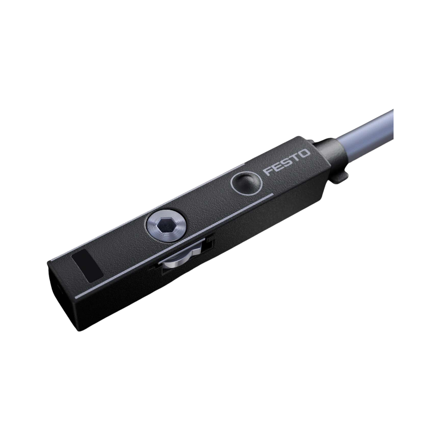
SDBT-MSX
Proximity Sensor
Instructions | Operating
8125856
201911a
[8125858]
Translation of the original instructions
© 2019 all rights reserved to Festo SE & Co. KG
1
Further applicable documents
All available documents for the product è www.festo.com/pk.
2
Safety
2.1
Intended use
This product is intended for sensing the position of magnets (e. g. the piston posi
tion) in Festo products. The device is intended for use in an industrial environ
ment.
2.1.1
Area of application and approval
In combination with the UL inspection mark on the product, the information in this
section must also be observed in order to comply with the certification conditions
of Underwriters Laboratories Inc. (UL) for USA and Canada.
UL approval information
Product category code
File number
Considered standards
UL mark
Tab. 1
Only use power sources which guarantee reliable electrical isolation of the oper
ating voltage in accordance with IEC/EN 602041. Observe also the general
requirements for PELV power circuits in accordance with IEC/EN 602041. Only for
connection to a NEC/CEC Class 2 supply. The device shall be supplied from an
isolating transformer having a secondary listed fuse rated 1 A.
3
Product overview
3.1
Structure
1 Connecting cable
2 Open cable end (SDBTMSX...LE)
3 Plug connector M8
(SDBTMSX...M8)
4 Marking of sensing range
Fig. 1
Festo SE & Co. KG
Ruiter Straße 82
73734 Esslingen
Germany
+49 711 3470
www.festo.com
8125856
NRKH, NRKH7
E232949
UL 609471, UL 6094752
C22.2 No. 609471, C22.2 No. 6094752
5 Green LED: display of sensing
range; only in teachin mode
6 Yellow LED: switching status dis
play
7 Retaining screw
8 Capacitive operating key
3.2
Function
The proximity sensor SDBTMSX detects the magnetic field of the piston magnet.
In the sensing range of the proximity switch, a switching point can be pro
grammed. To set a switching point in the sensing range of the proximity sensor,
there are two options:
–
Auto teachin
–
Capacitive operating key
1 Sensing range
2 Switching window
Fig. 2
4
Installation
4.1
Electrical
WARNING!
Risk of injury due to electric shock.
•
For the electrical power supply, use only PELV circuits in accordance with IEC
602041/EN 602041 (Protective ExtraLow Voltage, PELV).
•
Observe the general requirements of IEC 602041/EN602041 for PELV cir
cuits.
•
Only use voltage sources that ensure a reliable electric separation from the
mains network in accordance with IEC 602041/EN 602041.
Circuit diagrams
SDBT...PU...LE
SDBT...NU...LE
Tab. 2
4.2
Mechanical
•
Mount the proximity sensor in the end position of the piston so that the end
position is in the sensing range of the sensor. If available, the orientation aid
provides the marking of the piston end position on the drive.
1 Marking of the piston end position
on the drive (if available)
2 Retaining screw
Fig. 3
3 Hysteresis
4 Teachin point
SDBT...PU...M8
SDBT...NU...M8
3 Marking of sensing range
4 Tslot
Advertisement
Table of Contents

Related Manuals for Festo SDBT-MSX


Summary of Contents for Festo SDBT-MSX
- Page 1 This product is intended for sensing the position of magnets (e. g. the piston posi • Observe the general requirements of IEC 602041/EN602041 for PELV cir tion) in Festo products. The device is intended for use in an industrial environ cuits. ment.
- Page 2 Commissioning Menu structure Automatic switching point setting: auto teach-in Prerequisite: proximity sensor is in delivery status. Display with factory settings [NO] Both LEDs off: 1. Mount the proximity sensor roughly in the end positionè 4.2 Mechanical. Outside the sensing range; no switching point Green LED off &...
- Page 3 Dirt or moisture on the proximity – Wipe proximity sensor with a does not react to input sensor dry cloth Tab. 6 Technical data SDBT-MSX Operating voltage range [V DC] 10 … 30 Max. output current [mA] Operating temperature range [°C] –40 … +85 (UL: +80) Ambient temperature with [°C]...
Need help?
Do you have a question about the SDBT-MSX and is the answer not in the manual?
Questions and answers