Festo SDE5 Instructions & Operating
Pressure sensor
Hide thumbs
Also See for SDE5:
- Operating instructions manual (112 pages) ,
- Operating (42 pages) ,
- Operating instructions (4 pages)
Advertisement
Quick Links
SDE5
Pressure sensor
Instructions | Operating
8110091
201906f
[8110093]
Translation of the original instructions
1
Safety
1.1
General safety instructions
–
Only use the product in original status without unauthorised modifications.
–
Only use the product if it is in perfect technical condition.
–
Observe labelling on the product.
–
Condensation, oil mist, foreign matter and other contaminants in the com
pressed air can damage the product. Only use media in accordance with the
specifications è Technical data.
–
This product can generate high frequency interference, which may make it
necessary to implement interference suppression measures in residential
areas.
1.2
Intended use
The SDE5 is intended for pressure monitoring of gaseous media in piping systems
or terminal equipment in industry.
1.3
Training of qualified personnel
–
Installation, commissioning, maintenance and disassembly should only be
conducted by qualified personnel.
1.4
Area of application and approval
The information in this section, in combination with the UL marking on the
product, must be observed in order to ensure compliance with the certification
conditions of Underwriters Laboratories Inc. (UL) for USA and Canada. Observe
the following information in English by UL:
In determining the acceptability of the combination, the following details should
be examined:
–
The mounting suitability shall be determined in the enduse.
–
These devices shall be mounted in an enclosure having adequate strength
and thickness.
–
Devices should be used within its recognized ratings as specified under sec
tion RATINGS.
–
Devices have to be supplied from:
–
A Class 2 power source or Class 2 transformer in accordance with UL1310
or UL1585, or
–
An isolating device such that the maximum open circuit voltage potential
available to the circuit is not more than 30 Vdc and the current is limited
to a value not exceeding 8 amperes measured after 1 minute of opera
tion, or
–
A suitable isolating source in conjunction with a fuse in accordance with
UL248. The fuse shall be rated max. 3.3 A and be installed in the 30 Vdc
power supply to the device in order to limit the available current.
Note that, when more than one power supply or isolating device is used, connec
tion in parallel is not permitted.
–
The devices have not been investigated for fieldwiring.
–
The suitability should be determined in the enduse application.
UL approval information
Product category code
File number
Considered standards
UL mark
Tab. 1 UL approval information
2
Further information
–
Accessories è www.festo.com/catalogue.
–
Spare parts è www.festo.com/spareparts.
Festo SE & Co. KG
Ruiter Straße 82
73734 Esslingen
Germany
+49 711 3470
www.festo.com
8110091
NRNT2 (USA) and NRNT8 (Canada)
E253738
UL 508, 17th edition, C22.2 No.1405
3
Service
Contact your regional Festo contact person if you have technical questions
è www.festo.com.
4
Product overview
4.1
Configuration
4.1.1
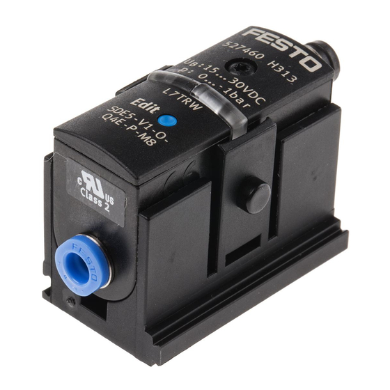
Product design
1 Electrical connection
2 LED indicator (continuous trans
mission of the LED indicator
through fibreoptic cable)
Fig. 1 Product design SDE5
MS series service unit component with pressure sensor SDE5
The pressure sensor SDE5 on the series MS service unit component is already per
manently attached and pneumatically connected in the delivery status.
Fig. 2 SDE5 installed on the MS series service unit component
MS series service unit component
MS4/6...AD7
MS4/6...AD8
MS4/6...AD9
MS4/6...AD10
Tab. 2 Assignment of service unit component MS and attached pressure sensor
4.1.2
LED display
LED
Meaning
LED illuminated
SDE5...P/N... (switching output): pressure p > switching pressure
(yellow)
LED off
SDE5...P/N... (switching output): pressure p < switching pressure
LED flashes
Teach procedure
quickly
(yellow)
LED flashes slowly
Only SDE5...FP: display and setting of the switching function
(yellow)
LED illuminated
Only SDE5...V (analogue output): ready status (RUN mode)
(green)
Tab. 3 Meaning of the LED indicator
4.2
Function
4.2.1
Functional principle
The SDE5 converts pneumatic pressure values into a voltage proportional to the
pressure. Depending on the design of the pressure sensor, the voltage signal is
converted into a digital switching signal (SDE5...P.../SDE5...N..) or amplified
for an analogue output (SDE5...NF...V).
3 Connection 2 for compressed air or
vacuum
4 Connection 1 for compressed air or
vacuum
5 Edit button (not on SDE5...X)
1 Edit button
2 LED indicator (continuous trans
mission of the LED indicator
through fibreoptic cable)
3 Electrical connection
Attached pressure sensor
SDE5D10O...PM8
SDE5D10C...PM8
SDE5D10O3...PM8
SDE5D10C3...PM8
Advertisement

Related Manuals for Festo SDE5


Summary of Contents for Festo SDE5
- Page 1 – Condensation, oil mist, foreign matter and other contaminants in the com The pressure sensor SDE5 on the series MS service unit component is already per pressed air can damage the product. Only use media in accordance with the manently attached and pneumatically connected in the delivery status.
- Page 2 Black (BK) Switching output A The SDE5 is available with different switch/teach functions . The switching func (Out A) or analogue tion is preset ex works and can only be changed for the SDE5...FP..output Blue (BU) 0 V Mounting...
- Page 3 Set the switching pressure SP with one teach pressure 1. Switch on the operating voltage. 1) The currently set mode is displayed 5 times in succession. The SDE5 then switches to RUN mode. 2. Apply teach pressure to SDE5. Tab. 11 Mode display 3.
- Page 4 Ä Teach pressure TP2 is stored. Note on the operating medi Lubricated operation possible 8. Ensure power supply for at least 10 seconds. 9. Test in test run whether SDE5 switches as desired. The LED lights when the Temperature of medium [°C] 0 … +50 switching signal is output.
Need help?
Do you have a question about the SDE5 and is the answer not in the manual?
Questions and answers