Danfoss VLT 5000 Series Installation Startup Check List
Hide thumbs
Also See for VLT 5000 Series:
- Instruction manual (240 pages) ,
- Operating instructions manual (192 pages) ,
- Manual (176 pages)
Advertisement
Quick Links
VLT 5000 Installation
• Reference material
• Pre-Installation
• Installation Checks
• Wiring
– Incoming Power
– Motor
– Brake
– Control
– Serial Communications
This presentation deals with the start-up of VLT 5000 drives. It is designed to help you
handle the start-up of the drive in normal applications. Because of the flexibility of these
drives, there may be some specialized applications that are not specifically covered by these
instructions. In that case, refer to the documentation that came with the drive for more
specific information.
This training module covers the installation and wiring of the VLT 5000. This section starts
with reference material, installation checks and then covers a number of wiring options.
Programming of the VLT 5000 is covers in another module.
Startup Check List
Advertisement

Related Manuals for Danfoss VLT 5000 Series


Summary of Contents for Danfoss VLT 5000 Series
- Page 1 VLT 5000 Installation Startup Check List • Reference material • Pre-Installation • Installation Checks • Wiring – Incoming Power – Motor – Brake – Control – Serial Communications This presentation deals with the start-up of VLT 5000 drives. It is designed to help you handle the start-up of the drive in normal applications.
- Page 2 DANGER Touching the electrical parts may be fatal — even after the equipment has been disconnected from the AC line. To be sure that the capacitors have fully discharged, wait 15 minutes after power has been removed before touching any internal component Because the drive uses large electrolytic capacitors in its power circuitry, it can maintain a dangerous voltage level for up to 15 minutes after power has been removed.
-
Page 3: Reference Material
Reference Material • Instruction Manuals • Connection Diagram • Schematic Diagram These three pieces of reference material might be available to you when you are starting up a drive. The VLT 5000 Instruction Manual provides general information on topics like mounting clearances, drive fuses, terminal tightening torques, and drive parameters. - Page 4 Hp to kW Chart Model Model 0.25 0.18 5032 30.0 22.0 0.33 0.25 5042 40.0 30.0 0.50 0.37 5052 50.0 37.0 0.75 0.55 5062 60.0 45.0 5001 0.75 5075 75.0 55.0 5002 5100 100.0 75.0 5003 5125 125.0 90.0 5004 5150 150.0 110.0...
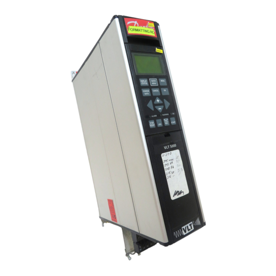
- Page 5 The Nameplates All Drives – On the Top or Left Side of the Drive Catalog Number Serial Number Sales Number Output Ratings of Drive The drive has two identifying numbers, the catalog number and the sales number. A Catalog Number, which is explained on the next slide, is the long number. In the example above the catalog number is VLT 5011-P-T2-CN1-ST-R0-DL-F00-A00.
- Page 6 Pre-Installation Check Catalog Order Number System (Found on page D 62 of the catalog) Example: VLT- 5008–P-T5-B20–EB-R0–DL-F00-A00-C0 VLT: Series 5XXX: Model Number -------------| P: Process Application -----------------| AC Line Voltage -----------------------------| T2: 3 phase 200 – 240 Vac T5: 3 phase 380 – 500 Vac T6: 3 phase 550 –...
-
Page 7: Pre-Installation Check
Pre-Installation Check • Be sure the Line Power, AFD and Motor have the same voltage range • Insure that all hand tools and kits are available. Before installing the drive, check to be sure that the power line, the drive, and the motor are all rated for the same voltage. - Page 8 Pre-Installation Check • Record motor data information – Motor Power – Motor Voltage – Motor Frequency – Motor Current (FLA) – Motor Speed (RPM) Write down the motor nameplate information. This will be important later during programming. A conversion between HP and kW must be calculated 1Hp = 0.75kW. In the example 20Hp = 15kW.
- Page 9 Pre-Installation Check • Always ensure that Drive can handle maximum current of the motor. • Example page 20 – VLT 5100 – CT, HO It is always important to check the technical data of the instruction manual for the drive you are installing to certify that the drive is able to handle the maximum current of the motor.
- Page 10 Pre-Installation Check • Check Motor Wiring – No power correction capacitors between drive and motor – 2-speed motors must be wired for full speed – Part-winding start motors, must be wired for run. Insure that there are no power correction capacitors between the drive and the motor. These types of capacitors must always be located on the incoming power to the drive, never the output of the drive.
-
Page 11: Installation Checks
Installation Checks • Fuses must be installed – Sized using Pages 34-35 in Instruction Manual To comply with UL / cUL, fuses must be wired on the incoming power side of the drive. The types of fuses are shown in the technical data section of the instruction manual. In the example above fuses and a disconnect switch are diagramed. - Page 12 Installation Checks • Environmental Concerns – Clean and Dry – 24-Hour temperature limit – page 214 – Altitude Limits – page 214 The VLT 5000 can be supplied with a NEMA 1(IP 20) or NEMA 12(IP 54) enclosure. These enclosures provides some degree of protection from falling dust. Therefore, drives with a NEMA 1(IP 20) and 12(IP 54) enclosures should be mounted indoors in a relatively clean and dry location.
- Page 13 Installation Checks • Mounting – Vertical – Flush Mounted Only In order to provide proper cooling, the drive must always be mounted vertically. It is also important to establish a "chimney" around the drive's heat sink to ensure that all cooling air passes along the entire length of the heat sink.
- Page 14 Installation Checks • Mounting – Side by Side is acceptable – Needs space above and below drive The VLT 5000 cools itself by drawing cooling air through the bottom of its enclosure and exhausting it out the top. It is therefore important to provide enough space above and below the drive to ensure proper flow of cooling air.
-
Page 15: Mounting The Drive
Mounting the Drive • Keep the drive clean – Use dust covers to keep construction dust from getting into it – Remove the dust covers before applying power If construction work continues after the drive is mounted, it is important to keep the drive as free as possible from concrete dust and similar dirt. -
Page 16: Wiring The Drive
Wiring the Drive • General Wiring • Power Input • Brake • Motor Output • Control • Serial Comms This next section covers the wiring of the drive. The first area to be covered is general wiring practices. The other sections cover power or line wiring from the drive to incoming power, brake wiring. - Page 17 Wiring the Drive • Conduit entry – All wiring enters the bottom of drive – Knock-outs are provided on many drives – Larger drives have a removable conduit entry or gland plate General Practices Most smaller drives have knock-outs for conduit entry. Larger drives provide a removable conduit entry plate.
- Page 18 Wiring the Drive • At least three separate METALLIC conduits must be connected to the drive – Power into the drive [L1, L2, L3 and a ground back to the distribution panel] – Power from the drive to the motor [U, V, W, and PE (power earth ground)] –...
- Page 19 Wiring the Drive • Input fuses – All drives must have input fuses installed in the power supply to the drive – Refer to the Instruction Manual for fuse sizing In order to fulfill the requirements of Underwriters Laboratory (UL) as was stated on page 11, all drives must be provided with fast-acting input power line fuses.
- Page 20 Wiring • General Information – Maximum voltage to control card is 24Vdc – Do NOT connect 120/240/460/575 to Control terminals – Use Relay 01, 02, 03 for 120 or 240Vac The maximum voltage for the control circuit must not exceed 24Vdc. A separate relay terminal 01, 02, 03 is used for higher voltages, 120/240 Vac.
- Page 21 Wiring • Motor Wiring – Use Terminals 96, 97, 98 – Check torque – page 53 – Distance limits – Disconnect OK A disconnect switch between the drive and motor may be required to meet electrical codes. During operation if the disconnect switch is opened, no harm is done to the drive or motor. If the disconnect is then closed and the drive is running, the motor may attempt to draw locked rotor current from the drive.
- Page 22 Wiring • Brake Wiring on SB & EB units – Use Terminals 88 & 89 for resistor – Load sharing for EB units – External 24Vdc. On Standard with Brake (SB) units there is an extra terminal labeled R – (81) and R + (82). The dynamic brake resistor is wired to these 2 terminals.
- Page 23 Wiring • Control Wiring – Digital Inputs – Analog Inputs – Analog Output – Digital/Relay Outputs This next section covers control wiring. It covers Digital Input Wiring first, followed by Analog Inputs. Analog Outputs are covered followed by Digital Outputs then Relay Outputs. It is always best to have control wiring in a separate conduit away from power wiring.
- Page 24 Wiring • Digital Inputs – 12 to 27 Enable – Jumper terminal 12 (+24Vdc) to terminal 27 (enable command) – Without jumper, bottom line of the display reads, “UNIT READY” and it does not operate the motor. When this jumper is made, the bottom line reads, “STANDBY”.
- Page 25 Wiring • Digital Inputs – Push button – Normally Open - Momentary – Functions: Latched Start (terminal 18 only) – Reset – Jog Push-Button (PB) Switch – Normally Open (NO) Some options: Latched Start can be configured using terminal 18 only. Reset can be accomplished from a remote location when the drive trips.
- Page 26 Wiring • Digital Inputs – Push Button – Normally Closed - Momentary – Stop Inverse means loss of 24Vdc to that terminal, stops the motor. – If multiple “stop” commands are required, additional terminals (16, 17, 27, 29, 32 and 33) can be wired in parallel each programmed for “Stop Inverse”.
- Page 27 Wiring • Digital Inputs – Push Button – Normally Closed (NC) - Momentary (Push Button) – Multiple stop commands can be wired in series to accommodate more stop commands. Any switch opens, stops the motor. If more stop commands are needed the diagram above shows multiple NC PB stop switches using one Digital Input.
- Page 28 Wiring • Digital Inputs – Pushbuttons - 3 Wire Start/Stop – Term. 18 (P 302) set to “Latched Start” – Term. 16 (P 300) set to “Stop Inverse” for terminal 17, 27, 29, 32 or 33. The diagram above shows the wiring for a 3-wire Start/Stop. Power comes from terminal 12, a source of +24Vdc.
- Page 29 Wiring • Digital Inputs – Pushbuttons - Changing the Reference – Pulsed Increase/Decrease Reference Speed – Term. 32 (P 306) set to “Speed UP”; Term. 33 (P 307) set to “Speed DOWN” – Term. 17 defaults to “Freeze Ref.” or on newer units set P 330 to “Freeze Reference”...
- Page 30 Wiring • Digital Inputs – Continuous – Single-pole, double throw (SPDT) – 2-wire Start/Stop using term 18. – Reverse using term 19 (P 303) – P 200 set to Both Directions – Other functions: Quick Stop, Direction Change, Ramp 2 Continuous Switch This diagram shows a 2-wire Start/Stop using terminal 18 which is programmed for Start.
- Page 31 Wiring • Digital Inputs – Multiple Starts from One command – Common connected, terminal 20, on each unit – Maximum of 200mV In the example above, one switch is used to start multiple drives. The +24Vdc from the first drive is being sent to the other drives. Notice that a wire most be connected between all the Digital Input commons, terminal 20.
- Page 32 Wiring • Digital Inputs – One switch ON/OFF and Direction – SPDT Center OFF – Terminal 18 (P 302) set for “Start” – Terminal 19 (P 303) set for “Start & Reverse” Single Pole Double Throw with Center OFF. This switch is used to start the drive in either direction, and turn it OFF in the center position. Notice that +24Vdc from terminal 12 goes to the center of the switch.
- Page 33 Wiring • Digital Inputs – Preset Speeds – 4 Preset Speeds set in Parameters 215, 216, 217 and 218 – 4-Position Switch using diodes for signal isolation – Parameter 214 is set to “External/Preset” – For additional presets up to maximum of 16, change between setups and presets.
- Page 34 Wiring • Digital Inputs – Changing Setups – 4-Position Switch and relay used for signal isolation – P 004 must be set to Multi Setup 4-position with a relay for Changing Setups In the diagram above a 4-position switch is used to shift between 4 different program setups.
- Page 35 Wiring • Digital Inputs – Encoder – A Channel showing speed comes into term 33 (P 307) – B Channel showing direction comes into term 32 (P 306) – +24Vdc power from terminal 13, common terminal 39 – P 329 sets PPR for Encoder –...
- Page 36 Wiring • Analog Inputs – 0 to 10Vdc – Potentiometer – Term 53 (P 308) set to “Reference” by default – Term 54 (P 311) set to “No operation” by default – Term 50 is +10Vdc; Term 55 is common Analog Input –...
- Page 37 Wiring • Analog Inputs – Potentiometer – P 203 is Min – Max or –Max to +Max – P 215 sets offset, may be negative In the diagram to the left, parameters are indicated to show the relationship between the signal coming from the pot and the reference. The signal from the pot is indicated on the left of the graph.
- Page 38 Wiring • Analog Inputs – One Potentiometer feeds multiple drives One Pot controlling multiple drives In the example above, one potentiometer is used to send a 0-10Vdc reference to the top drive. To send this same reference signal to the next drive, terminals 53 are wired together and terminals 55 (AI common) are wired together.
- Page 39 Wiring • Analog Inputs – 2-wire Transmitter – Term 12 or 13 supplies power +24Vdc – Jumper 39 to 55 to connect commons Analog Input – 2-wire Transmitter The picture above shows a 2-wire 4-20mA current transmitter. This type of transmitter requires power from the drive.
- Page 40 Wiring • Analog Inputs – 3-wire Transmitter – Term 12 or 13 supplies power +24Vdc – Transmitter’s Signal wired to terminal 60 (P 314 = Feedback). – Jumper 39 to 55 to connect commons Analog Input – 3-wire Transmitter The picture above shows a 3-wire 4-20mA current transmitter. This type of transmitter also requires power from the drive.
- Page 41 Wiring • Analog Outputs – Meter Indication – Terminal 42 and 45 set to AO or DO – If using 0-Fmax 0-20mA, meter trim is P 202. – New software – meter trim – use P 357 – 360. Analog Outputs The current meter shown above has its positive terminal wired to terminal 42 of the drive and the negative terminal wired to terminal 39.
- Page 42 Wiring • Analog Outputs – Master/Slave (Leader/Follower) – AO of Master to AI of Slave – Use 0-Fmax 4-20mA, use P 202 on master to match slope. – Use P 215 on slave to match intercept Analog Output – Master/Slave If 2 drives are to work together, at the same frequency, a master/slave (leader/follower) setup is of benefit.
- Page 43 Wiring • Analog Output - Pulse – Master/Slave (Leader/Follower) – DO of Master to DI of Slave set for Pulsed Reference – Use 0-Fmax 0-32,000 pulses, set max pulses to 32,000 use P 202 on master to match slope. – Use P 215 on slave to match intercept. Analog Output –...
- Page 44 Wiring • Digital/Relay Outputs – Digital Output powered +24Vdc – Relay Outputs are dry (no power) contacts Digital Outputs Terminals 42 and 45 besides being used as Analog Outputs can also be used as Digital Outputs. Digital Outputs are always +24Vdc powered 2-state outputs. In the diagram to the left a 24Vdc light is wired directly to terminals 42 (DO signal) and 39 (common).
- Page 45 Wiring • Serial Communications – Need repeater (amplifier) after 31 drives attached together – Dip switch settings 2 & 3 to OFF except for 2 bus ends Serial Communications This diagram shows how the serial communications is wired. Notice that it is an RS- 485 connection, which means that all the positive terminals (68) are wired together and all the negatives (69) are wired together.
Need help?
Do you have a question about the VLT 5000 Series and is the answer not in the manual?
Questions and answers