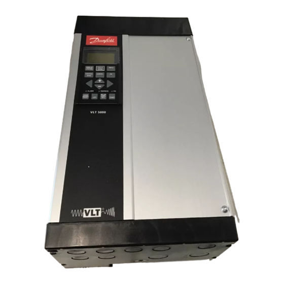
Danfoss VLT 5000 Interbus Series Technical Data Manual
Hide thumbs
Also See for VLT 5000 Interbus Series:
- Instruction manual (240 pages) ,
- Operating instructions manual (192 pages) ,
- Manual (176 pages)
Advertisement
Quick Links
Advertisement

Subscribe to Our Youtube Channel
Summary of Contents for Danfoss VLT 5000 Interbus Series
- Page 1 5000 INTERBUS ®...
- Page 2 5000 INTERBUS ® I About this manual I Assumptions I What you should already know...
- Page 3 5000 INTERBUS ® Available literature Instructions Var. literature Instructions Communication for VLT for VLT 5000 for VLT 5000 for VLT 5000 5000 Series Series Series Series Design Brake VLT Software Guide instructions Dialog Operating MI.50.DX.YY MG.50.CX.YY MG.50.EX.YY Instructions MG.50.AX.YY LCP remote- mounting kit VLT 5000 PROFIBUS...
- Page 4 5000 INTERBUS ®...
- Page 5 5000 INTERBUS ® Technical Data Cable lengths/number of nodes < <...
- Page 6 5000 INTERBUS ® Ordering number.
- Page 7 5000 INTERBUS ®...
- Page 8 5000 INTERBUS ® I LEDs Connectors IBS in IBS Out MK 100A MK 100B IBS Out IBS in...
- Page 9 5000 INTERBUS ® RBST C O M C O M C O M C O M RBST C O M C O M...
- Page 10 5000 INTERBUS ®...
- Page 11 5000 INTERBUS ®...
- Page 12 5000 INTERBUS ®...
- Page 13 5000 INTERBUS ® I Process Data. PCD1 PCD2 PCD3 PCD4 PCD5 PCD PCD1 PCD2 PCD3 PCD4 PCD5 PCD6 INTERBUS VLT®5000 STW MAV...
- Page 14 5000 INTERBUS ® I Process Data, PCD. Interbus objects 6 0 0 1 6 0 4 0 C T W 0 0 0 0 VLT5000 6 0 4 2 Parameters M R V 0 0 0 0 5 6 B C 2 0 4 915 [1] P C D 1...
- Page 15 5000 INTERBUS ® Drivecom State machine State A transition 0 condition xxxx xx0x State B drawing: to change from STW = xx01h state A to state B, the condition Controlword bit 1 has to be set equal to 0. The coarses the transition 0 to be exequted.
- Page 16 5000 INTERBUS ® ➠ ➠ ➠ ➠ ➠ ➠ ➠ ➠ ➠ ➠ ➠ ➠ ➠ ➠ ➠ ➠...
- Page 17 5000 INTERBUS ® ➝ bus, logic or logic and logic and...
- Page 18 5000 INTERBUS ® ➝ Local operation...
- Page 19 5000 INTERBUS ® ➝ ➝...
- Page 20 5000 INTERBUS ® I Drivecom 21 objects. α α α α α α α ∆ ∆ ∆ ∆ ∆ ∆ ∆ ∆ ∆ ∆ α α ∆ ∆ ∆ ∆ ∆ α α α α α ∆ ∆ ∆ ∆ ∆...
- Page 21 5000 INTERBUS ® Interbus Error codes:...
- Page 22 5000 INTERBUS ® I PCP Communication.
- Page 23 5000 INTERBUS ® ➝ Relay 123 ramping...
- Page 24 5000 INTERBUS ® ➝ Control word bit Control word bit ≠ Multi-Setup bus, logic or logic and logic and...
- Page 25 5000 INTERBUS ® ≠ ➝ Local operation ➝...
- Page 26 5000 INTERBUS ® I INTERBUS specific VLT parameters Function: time out Stop w. trip ⇒ Local ⇒ Disabled ⇒ Off ⇒ 801 Baud rate select (BAUD RATE SELECT) Selection: Description of selections: ✭ Freeze output frequency Function: Stop with auto restart Output frequency = JOG freq.
- Page 27 5000 INTERBUS ® Description of selections: 916 PCD config. read(PCD IN RD-) 807 PCD size select (PCD SIZE SELECT) Selections: Selection: ✭ Function: Function: 915 PCD config. write (PCD IN WR-) Description of selections: Selections: ≈ ≈ 927 Parameter edit Selections: ✭...
- Page 28 5000 INTERBUS ® 928 Process control Selections: ✭ Function: 971 Store data values (STORE DATA VALUE) Selections: ✭ Description of selections: Function: Disabled Enabled Description of selections: No action: Store active setup: 953 Warning parameter 1 (WARN. PARA) No action Selections: Store all setups No action...
- Page 29 5000 INTERBUS ® 990-992 Modified parameters (MODIFIED PNU'S) Selections: Function: read...
- Page 30 5000 INTERBUS ® I I I I I VLT response time I I I I I System update time VLT®5000 Interbus Control option Card Master...
- Page 31 5000 INTERBUS ® I Warning and alarm messages I I I I I Additional display messages...
- Page 32 5000 INTERBUS ® I Abbriviations.
- Page 33 5000 INTERBUS ® I VLT5000 parameter list.
- Page 34 5000 INTERBUS ® Conversion Data index type...
- Page 35 5000 INTERBUS ® Conversion Data index type ⇒ ⇒...
- Page 36 5000 INTERBUS ®...
- Page 37 5000 INTERBUS ®...
- Page 38 5000 INTERBUS ®...


Need help?
Do you have a question about the VLT 5000 Interbus Series and is the answer not in the manual?
Questions and answers