Table of Contents
Advertisement
Quick Links
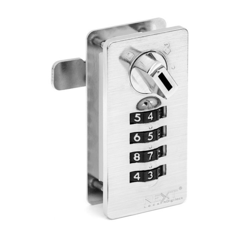
Lock Parts
Front Unit
Locked Position
Key Slot
Accommodates door
Spacer required* for door
Installation Guide
thickness up to 20 mm
thickness less than 8 mm
Spacer required* for door
Mounting plate
Accommodates door
thickness less than 8 mm
thickness up to 20 mm
Mounting plate
Spacer required* for door
Accommodates door
thickness less than 8 mm
thickness up to 20 mm
Spacer required* for door
Mounting plate
Mounting
thickness less than 8 mm
Screws
Mounting plate
Mounting
Screws
Mounting
Screws
Mounting
Screws
Manager key
Factory default combination 0-0-0-0
Setup
Manager key
Removal key
Factory default combination 0-0-0-0
Manager key
Manager key
Removal key
Assign a User Combination
Factory default combination 0-0-0-0
Factory default combination 0-0-0-0
Once a new user combination is assigned, the previously assigned user combination will no longer operate the lock. If the current user code
is unknown, follow the Reset Combination instructions to find the current assigned code then continue to Assign a new User Combination.
1.
Set the dial to show the current assigned combination.
2.
Insert the Programming Key and turn the knob to the
circle mark
position.
3.
Set any 4-digit combination.
Note: Removing the Programming Key in the circle mark
Unlocked Position
Programming
Position
Comibination Dial
Accommodates door
thickness up to 20 mm
Removal key
Removal key
position will remove the core. See Replace Key Set and Core instructions to reinsert the core.
Product Guide
Dial Combo
Rear Unit
Reset Pin Holes
Cam in Locked Position
must overlap Strike
Plate by at least ¼"
(6.35 mm)
Cam in Locked Position
must overlap Strike
Plate by at least ¼"
(6.35 mm)
Spacer Requirements
Door thickness
Spacer Requirements
0 – 5 mm
Spacer Requirements
5 – 8 mm
Door thickness
8 – 12 mm
Door thickness
Screw type
0 – 5 mm
12 – 16 mm
0 – 5 mm
M3×10
5 – 8 mm
16 – 20 mm
5 – 8 mm
M3×14
8 – 12 mm
8 – 12 mm
M3×10
12 – 16 mm
12 – 16 mm
M3×14
16 – 20 mm
16 – 20 mm
M3×18
4.
Turn the knob to the locked
Programming Key.
5.
Scramble the code.
Assigned Use
Cam
Mortise Hole Dimensions
Mortise Hole Dimensions
Cam in Locked Position
must overlap Strike
Mortise Hole Dimensions
Plate by at least ¼"
min. 6.35 mm
(6.35 mm)
31.5 mm
Mortise Hole Dimensions
min. 6.35 mm
Cam in Locked Position
31.5 mm
must overlap Strike
Plate by at least ¼"
min. 6.35 mm
(6.35 mm)
31.5 mm
Spacer Requirements
Door thickness
Screw type
*Spacer required
0 – 5 mm
M3×10
5 – 8 mm
M3×14
8 – 12 mm
M3×10
12 – 16 mm
M3×14
Screw type
*Spacer required
16 – 20 mm
M3×18
✓
M3×10
✓
M3×14
Screw type
*Spacer required
M3×10
✓
*Spacer required
M3×10
M3×14
✓
✓
M3×14
✓
M3×18
M3×10
M3×14
M3×18
position and remove the
min. 6.35 mm
31.5 mm
✓
✓
Advertisement
Table of Contents

Related Manuals for Digilock Next Mech


Summary of Contents for Digilock Next Mech
- Page 1 Product Guide Dial Combo Assigned Use Lock Parts Front Unit Rear Unit Locked Position Unlocked Position Key Slot Programming Position Comibination Dial Reset Pin Holes Accommodates door thickness up to 20 mm Mortise Hole Dimensions Accommodates door Spacer required* for door Installation Guide thickness up to 20 mm Mortise Hole Dimensions...
- Page 2 thickness up to 20 mm Product Guide Spacer required* for door thickness less than 8 mm Dial Combo Mounting plate Assigned Use Operating Instructions Mounting Screws Operate with a Combination To Lock: To Unlock: Close the door. Enter the assigned 4-digit combination. Turn the knob to the locked position.
- Page 3 Mounting screws Replace Key Set and Core Please contact support@digilock.com if your Manager or Programming key(s) are lost or stolen to purchase a new set of keys and replacement cores for all locks. If your Manager Key was lost or stolen, you can remove lock cores with your existing Programming key. Once you remove the lock cores, contact support@digilock.com to purchase a new set of keys and lock cores.
Need help?
Do you have a question about the Next Mech and is the answer not in the manual?
Questions and answers