
Related Manuals for HMS Intesis KNX Mitsubishi Electric CC


Summary of Contents for HMS Intesis KNX Mitsubishi Electric CC
- Page 1 Gateway for integration of Mitsubishi Electric City Multi air conditioning systems to KNX home automation systems USER MANUAL Issue date: 05/2019 r1.1 ENGLISH...
- Page 2 HMS Industrial Networks reserves the right to modify its products in line with its policy of continuous product development. The information in this document shall therefore not be construed as a commitment on the part of HMS Industrial Networks and is subject to change without notice.
- Page 3 Gateway for integration of Mitsubishi Electric City Multi air conditioning systems into KNX home automation systems. ORDER CODE LEGACY ORDER CODE INKNXMIT015C000 ME-AC-KNX-15 INKNXMIT100C000 ME-AC-KNX-100 © HMS Industrial Networks S.L.U - All rights reserved https://www.intesis.com This information is subject to change without notice 3 / 32...
-
Page 4: Table Of Contents
5 Electrical & Mechanical Features ........................23 6 Dimensions ................................. 24 7 Appendix A – Communication Objects Table ..................... 25 © HMS Industrial Networks S.L.U - All rights reserved https://www.intesis.com This information is subject to change without notice 4 / 32... -
Page 5: Description
Ethernet TCP Mitsuibishi Electric’s M-NET KNX TP-1 configuration Ethernet configuration Integration of Mitsubishi's Centralized Controller into KNX home automation systems © HMS Industrial Networks S.L.U - All rights reserved https://www.intesis.com This information is subject to change without notice 5 / 32... -
Page 6: Functionality
INKNXMIT015C000. Model supporting up to 15 City Multi groups. • INKNXMIT100C000. Model supporting up to 100 City Multi groups. © HMS Industrial Networks S.L.U - All rights reserved https://www.intesis.com This information is subject to change without notice 6 / 32... -
Page 7: Knx System
If activated, the point will be active in Intesis, if not, the behaviour will be as if the point is not defined. This allows deactivating points without the need of delete them for possible future use. © HMS Industrial Networks S.L.U - All rights reserved https://www.intesis.com This information is subject to change without notice... - Page 8 See list of communication objects, according to unit type in section 7 © HMS Industrial Networks S.L.U - All rights reserved https://www.intesis.com This information is subject to change without notice...
-
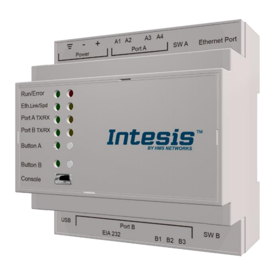
Page 9: Connections
Connect a USB storage device (not a HDD) if required. Check the user manual for more information. Ensure proper space for all connectors when mounted (see section 66). © HMS Industrial Networks S.L.U - All rights reserved https://www.intesis.com This information is subject to change without notice... -
Page 10: Power Device
• USB cable: To connect the device to the PC, the USB cable supplied should be plugged to the USB Console port. © HMS Industrial Networks S.L.U - All rights reserved https://www.intesis.com This information is subject to change without notice... -
Page 11: Set-Up Process And Troubleshooting
4.2.2 Connection To configure the Intesis connection parameters press on the Connection button in the menu bar. Figure 4.1 MAPS connection © HMS Industrial Networks S.L.U - All rights reserved https://www.intesis.com This information is subject to change without notice 11 / 32... -
Page 12: Configuration Tab
1.1. Physical Address. KNX physical address of the device in the network 1.2. Extended Addresses. Enables usage of KNX Extended addresses (rangefrom 16/0/0 to 32/7/255). © HMS Industrial Networks S.L.U - All rights reserved https://www.intesis.com This information is subject to change without notice... - Page 13 4. Fan Speed. Settings related to KNX interface for control and feedback of Mitsubishi unit’s fan speed. 4.1. Auto Fan Speed. Configures availability of Auto Fan Speed control/monitoring objects. Necessary if your indoor unit has auto fan speed. © HMS Industrial Networks S.L.U - All rights reserved https://www.intesis.com This information is subject to change without notice...
- Page 14 5.4. Use of 1-bit Vane Position. 1-bit Control Objects. Enables a bit-type object for control of vane position. 5.5. Use of 1-bit Vane Position. 1-bit Status Objects. Enables a bit-type object for monitoring of each vane position. © HMS Industrial Networks S.L.U - All rights reserved https://www.intesis.com This information is subject to change without notice...
-
Page 15: Mitsubishi Electric Configuration
You can do it manually in ‘Controllers Configuration’ section, by unfolding the corresponding ‘Centralized Controller’ in the list of controllers. You can also scan for available groups under the IP of the Centralized Controller: © HMS Industrial Networks S.L.U - All rights reserved https://www.intesis.com This information is subject to change without notice... - Page 16 A progress bar will appear during the scan, which will take a few seconds (up to 1 or 2 minutes). After scan is completed, detected groups will be shown in the ‘Available Groups’ area, as follows: © HMS Industrial Networks S.L.U - All rights reserved https://www.intesis.com...
- Page 17 Figure 4.8 Scan results window Parameters that must be configured for each group are the following: 1. Description: Text description for the control Group © HMS Industrial Networks S.L.U - All rights reserved https://www.intesis.com This information is subject to change without notice...
- Page 18 Finally, in addition to Centralized Controller parameters, and parameters for each corresponding group, there is a set of advanced global parameters defining the communication of the Intesis with the centralized controller. These are following: © HMS Industrial Networks S.L.U - All rights reserved https://www.intesis.com This information is subject to change without notice...
- Page 19 3. Controller Connection Timeout: After Intesis starts TCP/IP socket connection, time that the Intesis will wait for the Centralized Controller to accept the socket request. For each individual request, Intesis starts a new socket connection. © HMS Industrial Networks S.L.U - All rights reserved https://www.intesis.com This information is subject to change without notice...
-
Page 20: Signals
Figure 4.11 Intesis MAPS Receive/Send tab After any configuration change, do not forget to send the configuration file to the Intesis using the button “Send”. © HMS Industrial Networks S.L.U - All rights reserved https://www.intesis.com This information is subject to change without notice... -
Page 21: Diagnostic
Figure 4.12 Diagnostic More information about the Diagnostic section can be found in Intesis MAPS user manual for Intesis KNX Series. © HMS Industrial Networks S.L.U - All rights reserved https://www.intesis.com This information is subject to change without notice... -
Page 22: Set-Up Procedure
Modbus devices, check that those are operative: check the baud rate, the communication cable used to connect all devices and any other communication parameter. Figure 4.13 Enable COMMS © HMS Industrial Networks S.L.U - All rights reserved https://www.intesis.com This information is subject to change without notice... -
Page 23: Electrical & Mechanical Features
ON: 120 Ω termination active 100 mm Switch B Off: 120 Ω termination inactive SWB) Position 2-3: ON: Polarization active Off: Polarization inactive © HMS Industrial Networks S.L.U - All rights reserved https://www.intesis.com This information is subject to change without notice 23 / 32... -
Page 24: Dimensions
Recommended available space for its installation into a cabinet (wall or DIN rail mounting), with space enough for external connections 100 mm (h) 100 mm (w) 130 mm (d) © HMS Industrial Networks S.L.U - All rights reserved https://www.intesis.com This information is subject to change without notice 24 / 32... -
Page 25: Appendix A - Communication Objects Table
Speed 3; 4 – Speed 4 1 – Set auto fan Fan Speed AUTO (all the IC groups) 1 bit DPT_Switch 1.001 © HMS Industrial Networks S.L.U - All rights reserved https://www.intesis.com This information is subject to change without notice 25 / 32... - Page 26 1.001 0 – Cool mode not active; 1 – Status_Cool mode IC 1 bit DPT_Switch 1.001 Cool mode active © HMS Industrial Networks S.L.U - All rights reserved https://www.intesis.com This information is subject to change without notice 26 / 32...
- Page 27 OP MODE Heating_Eco; 3 – Anti_Freeze; 4 Status_Operation mode ATW & HWHP 1 byte Non-standarized ATW / – Cooling HWHP © HMS Industrial Networks S.L.U - All rights reserved https://www.intesis.com This information is subject to change without notice 27 / 32...
- Page 28 100% – Speed 3 0-74% – Speed 1; 75-100% – Control_Fan Speed scaling (2stages) 1 byte DPT_Scaling 5.001 Speed 2 © HMS Industrial Networks S.L.U - All rights reserved https://www.intesis.com This information is subject to change without notice 28 / 32...
- Page 29 DPT_Switch 1.001 0 – Position-3 Vane not active; 1 Status_Vane position-3 1 bit DPT_Switch 1.001 – Position-3 Vane active © HMS Industrial Networks S.L.U - All rights reserved https://www.intesis.com This information is subject to change without notice 29 / 32...
- Page 30 Status_group error code 2 byte Non-standarized ERROR code 1 – Reset command Control_group error reset 1 bit DPT_Reset 1.015 © HMS Industrial Networks S.L.U - All rights reserved https://www.intesis.com This information is subject to change without notice 30 / 32...
- Page 31 Status_Setback lower temperature setpoint (ºC) 2 byte DPT_Value_Temp 9.001 4,5-90ºC Control_Cooling ATW temperature setpoint (ºC) 2 byte DPT_Value_Temp 9.001 4,5-90ºC © HMS Industrial Networks S.L.U - All rights reserved https://www.intesis.com This information is subject to change without notice 31 / 32...
- Page 32 0 – Filter OK; 1 – Filter Dirty Status_Filter 1 bit DPT_Alarm 1.005 FILTER 1 – Reset command Control_Dirty filter indication reset 1 bit DPT_Reset 1.015 © HMS Industrial Networks S.L.U - All rights reserved https://www.intesis.com This information is subject to change without notice 32 / 32...
Need help?
Do you have a question about the Intesis KNX Mitsubishi Electric CC and is the answer not in the manual?
Questions and answers