
Related Manuals for Keysight M9217A PXIe 2-CH


Summary of Contents for Keysight M9217A PXIe 2-CH
- Page 1 Keysight M9217A PXIe 2-CH Digitizer, Isolated, ±256 V, 20 MSa/s, 16-Bit Inspection, verification, and installation for M9217A PXIe 2-CH digitizer Startup Guide...
- Page 2 AGREEMENT WITH WARRANTY TERMS fully understood and met. Support COVERING THE MATERIAL IN THIS DOCUMENT THAT CONFLICT WITH To contact Keysight for sales and THESE TERMS, THE WARRANTY TERMS technical support, refer to the "support" WARNING IN THE SEPARATE AGREEMENT links on the following Keysight Web WILL CONTROL.
- Page 3 When installing equipment where access component, call a Keysight office ensuring that the equipment is to the main power cord is restricted, such for information.
- Page 4 Do not attempt to clean internally. To clean the connectors, use alcohol in a well- ventilated area. Allow all residual alcohol moisture to evaporate, and the fumes to dissipate prior to energizing the instrument. Keysight M9217A Startup Guide...
- Page 5 Industrial Scientific and Medical Group 1 Class A product (CISPR 11, Clause 4). This symbol indicates the time period during which no hazardous or toxic substance elements are expected to leak or deteriorate during normal use. Forty years is the expected useful life of the product. Keysight M9217A Startup Guide...
- Page 6 “Monitoring and Control Instrument” product. The affixed product label is as shown below. Do not dispose in domestic household waste. To return this unwanted instrument, contact your nearest Keysight Service Center, or visit www.keysight.com/environment/product for more information.
- Page 7 THIS PAGE HAS BEEN INTENTIONALLY LEFT BLANK. Keysight M9217A Startup Guide...
-
Page 8: Table Of Contents
Power up the controller 20 Install the software 20 Step 4: Install the Module 22 M9217A front panel 26 M9217A system connections 27 Step 5: Verify the Operation of the M9217A Module 28 Conduct performance verification (optional) 29 Specifications 34 Keysight M9217A Startup Guide... - Page 9 THIS PAGE HAS BEEN INTENTIONALLY LEFT BLANK. Keysight M9217A Startup Guide...
- Page 10 InstallShield Wizard for Keysight M9217A 21 Figure 3 Installing the module to the chassis 23 Figure 4 Module installation procedures 25 Figure 5 M9217A PXIe 2-CH Digitizer front panel 26 Figure 6 M9217A functional block diagram 27 Figure 7 SFP interface 28 Figure 8...
- Page 11 THIS PAGE HAS BEEN INTENTIONALLY LEFT BLANK. Keysight M9217A Startup Guide...
- Page 12 List of Tables Table 1 Minimum system requirements 19 Table 2 Required functionality verification hardware 29 Table 3 Configuration for digitizer 31 Table 4 Suggested calibrator output voltages 32 Keysight M9217A Startup Guide...
- Page 13 THIS PAGE HAS BEEN INTENTIONALLY LEFT BLANK. Keysight M9217A Startup Guide...
-
Page 14: Introduction
– Keysight M9217A PXIe 2-CH Digitizer, Isolated, ±256 V, 20 MSa/s, 16-Bit Programming Guide. For IVI-COM console applications. – Keysight M9217A PXIe 2-CH Digitizer, Isolated, ±256 V, 20 MSa/s, 16-Bit Soft Front Panel Software and Help. Embedded in the Soft Front Panel software. -
Page 15: Step 1: Unpack And Inspect The Module
Electrostatic discharge (ESD) can damage or destroy electronic components. All work on electronic assemblies should be performed at a static-safe work station. The following figure shows an example of a static-safe work station using two types of ESD protection. Figure 1 Static-safe work station example Keysight M9217A Startup Guide... -
Page 16: Inspect The Module For Damage
(Warranty information can be found at the beginning of this manual.) To avoid damage when handling a module, do not touch exposed connector pins. CAUTION Information on preventing damage to your Keysight equipment can be found at NOTE www.keysight.com/find/tips. Keysight M9217A Startup Guide... -
Page 17: Return The Module For Service
Should it become necessary to return the M9217A for repair or service, follow the steps below: 1 Review the warranty information shipped with your product. 2 Contact Keysight to obtain a Return Material Authorization (RMA) and return address. If you need assistance finding Keysight’s contact information, go to www.keysight.com/find/assist... -
Page 18: Step 2: Verify The Shipment Contents
Step 2: Verify the Shipment Contents The following items are included in the M9217A shipment: – M9217A PXIe 2-CH Digitizer, Isolated, ±256 V, 20 MSa/s, 16-Bit Software and Product Information CD-ROM (P/N: M9217-10001) - contains software, drivers, and all product documentation in PDF format –... -
Page 19: Step 3: Install The Software
A Keysight M9045A ExpressCard interface (for portable laptops) or Keysight M9047A PCIe interface (for desktop Remote controller PCs) or equivalent PXIe remote controllers running one of the above operating systems. A Keysight M9021A System Interface Card, or equivalent embedded controller running one of the above operating systems. Embedded controller Note: The embedded controller must be compatible with the Keysight M9018A chassis. -
Page 20: Power Up The Controller
Keysight website: www.keysight.com/find/m9217a. This installation includes the following: – Keysight IO Libraries Suite (IOLS), which includes the Keysight Connection Expert. – Soft Front Panel (SFP), device drivers (IVI-C and IVI-COM, and LabVIEW G), and related user documentation for the M9217A. - Page 21 Figure 2 InstallShield Wizard for Keysight M9217A 3 After installation is complete, power down the chassis (and the host PC if using the remote controller). Keysight M9217A Startup Guide...
-
Page 22: Step 4: Install The Module
Blockage by walls or obstructions affects the air flow needed for cooling. (Refer to the chassis documentation for more information about cooling). 4 If you are using an embedded controller, proceed to step 5. If you using a remote controller, skip to step 6. Keysight M9217A Startup Guide... - Page 23 10 Install all chassis covers and filler panels after installing the module. Missing filler panels may disrupt necessary air circulation in the chassis. 11 If you are using a remote controller, connect the System Interface Card in the chassis to host computer. Keysight M9217A Startup Guide...
- Page 24 13 If you are using a remote controller, reboot the host PC. Tighten the screws on the module front panel. Protection provided by the equipment WARNING could be impaired if the screws are not tightened properly. Keysight M9217A Startup Guide...
- Page 25 3 Seat the M9217A module into the mainframe by pulling up the ejector. 4 Tighten the top and bottom screws to secure the M9217A module to the mainframe. Figure 4 Module installation procedures Keysight M9217A Startup Guide...
-
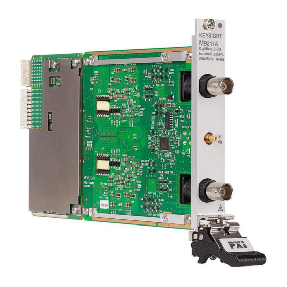
Page 26: M9217A Front Panel
M9217A front panel Figure 5 M9217A PXIe 2-CH Digitizer front panel Keysight M9217A Startup Guide... -
Page 27: M9217A System Connections
M9217A system connections Figure 6 M9217A functional block diagram Keysight M9217A Startup Guide... -
Page 28: Step 5: Verify The Operation Of The M9217A Module
You may use the SFP as a learning tool to help you experience the module's capability and behavior through a user-friendly graphic interface. You may refer to Keysight M9217A Soft Front Panel Help for details on how to use the SFP. Keysight M9217A Startup Guide... -
Page 29: Conduct Performance Verification (Optional)
Verifying the functionality of the module requires external equipment. Refer to Table 2 for the recommended functionality verification hardware. Table 2 Required functionality verification hardware Hard ware Description PXIe chassis PXIe requirements PXIe slot-1 controller Fluke 5700A Multifunction calibrator Keysight M9217A Startup Guide... - Page 30 Use BNC T-connectors near the channel inputs. Figure 8 Connecting the calibrator output to the channel inputs on the digitizer 3 Configure the digitizer using SFP as shown in Table 3 or Figure 9. Keysight M9217A Startup Guide...
- Page 31 Configuring the digitizer 4 Set the calibrator to output -0.235 V. 5 On the M9217A PXIe 2-CH Digitizer SFP, click on the Acquire Data tab. Click on Single to measure. The result will be displayed as shown in Figure 10.
- Page 32 8 If any values are out of range, refer to “Return the module for service” on page details on sending the module to Keysight Technologies for service. Table 4 Suggested calibrator output voltages...
- Page 33 50 Ω termination to the input connectors. Shock Hazard. This procedure requires the application of up to 240 Vdc. Ensure all test WARNING conections are properly insulated and shielded. Keysight M9217A Startup Guide...
-
Page 34: Specifications
Specifications Complete specifications for the M9217A (M9217A Data Sheet, 5992-0366EN) are included on the Keysight M9217A Software and Product Information CD-ROM that came with your module. Please check the Keysight website at www.keysight.com/find/m9217a for the latest updates on these specifications. - Page 35 THIS PAGE HAS BEEN INTENTIONALLY LEFT BLANK. Keysight M9217A Startup Guide...
- Page 36 This information is subject to change without notice. Always refer to the English version at the Keysight website for the latest revision. © Keysight Technologies 2015 Edition 1, October 1, 2015 *M9217-90001* M9217-90001 www.keysight.com...
Need help?
Do you have a question about the M9217A PXIe 2-CH and is the answer not in the manual?
Questions and answers