Table of Contents
Advertisement
Available languages
Available languages
Installation, Service and User Instructions
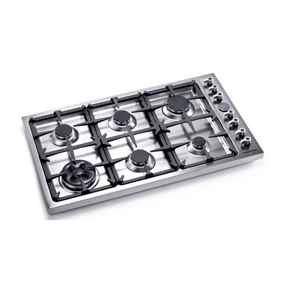
Built-in gas hotplates
DIMENSIONS: 36
IMPORTANT: SAVE FOR LOCAL ELECTRICAL INSPECTOR'S USE.
READ AND SAVE THESE INSTRUCTIONS FOR FUTURE REFERENCE.
OBSERVE ALL GOVERNING CODES AND ORDINANCES.
WARNING: If the information in this manual is not followed exactly, a fire or
explosion may result causing property damage, personal injury or death.
Do not store or use gasoline or other flammable vapors and liquid in the vicinity of
this or any other appliance.
WHAT TO DO IF YOU SMELL GAS
- Do not try to light any appliance.
- Do not touch any electrical switch.
- Do not use any phone in your building.
- Immediately call your gas supplier from a neighbor's phone. Follow
the gas supplier's instructions.
- If you cannot reach your gas suppliers, call the fire department.
Installation and service must be performed by a qualified installer, service agency
or the gas supplier.
Read this instruction booklet before installing and using the appliance.
The manufacturer will not be responsible for any damage to property or to persons caused by
incorrect installation or improper use of the appliance.
The manufacturer reserves the right to make changes to its products when considered necessary and useful,
without affecting the essential safety and operating characteristics.
This appliance has been designed for non-professional, domestic use only.
(French version page 10)
1/2
Models B3W0..U4X(2 or 5)D
Models B3Y0..U4X(2 or 5)D
BERTAZZONI
''
(W) x 21
(925 mm)
''
(D)
1/4
(540 mm)
Type 'A'
Type 'B'
Cod. 310283
Advertisement
Table of Contents

Related Manuals for Bertazzoni Professional Series D36600X


Summary of Contents for Bertazzoni Professional Series D36600X
- Page 1 The manufacturer reserves the right to make changes to its products when considered necessary and useful, without affecting the essential safety and operating characteristics. This appliance has been designed for non-professional, domestic use only. (French version page 10) BERTAZZONI ’’ (925 mm) (W) x 21 ’’...
-
Page 2: Table Of Contents
INDEX: Installation Instructions……………………………………..………………………..pag.2 Inserting the hotplate……………………………………………..…………………..pag.3 Requirements……………………………………..……………………………….…..pag.3 Attaching the hotplate……………………………………..………………………….pag.4 Gas connection……………………………………..…………………………………pag.4 Electrical connection……………………………………..……………………….…..pag.5 Wiring diagrams……………………………………..…………………………….…..pag.5 Room ventilation…………………………………….…………………………………pag.5 Location and venting…………………………………….…………………………….pag.5 Replacement of nozzles……………………………………..………………………..pag.5 Regulation of burners……………………………………………...………………….pag.6 Descriptions…………………………………………………………………………….pag.6 Service & maintenance instructions……………………………..…………………..pag.6 Greasing the valves……………………………………………..…………………….pag.7 User instructions……………………………………………..………………………..pag.7 Using burners……………………………………………………..……………………pag.7 Cleaning the appliance……………………………………………..…………………pag.8 Figures………………………………………………...…………..……………………pag.19 Installation instructions This appliance shall only be installed by an authorized person. -
Page 3: Inserting The Hotplate
The minimum gas supply pressure for checking the regulator setting shall be at least 1“ w.c. (249 Pa) above the inlet specified manifold pressure to the appliance (this operating pressure is 4” w.c. (1.00 kPa) for Natural Gas and 11” w.c. (2.75 kPa) for LP Gas). ATTENTION: A manual valve shall be installed in an accessible location in the gas line external to the appliance for the purpose of turning on or shutting off gas to the appliance WARNING: Do not use aerosol sprays in the vicinity of this appliance while it is in operation... -
Page 4: Attaching The Hotplate
Attaching the hotplate To prevent liquids from leaking accidentally into the underlying storage space, the appliance is equipped with a special gasket. To apply this gasket, carefully follow the instructions in Fig. 3. Lay out the protective sealing strips along the edges of the opening in the bench top and carefully overlap the strip end. (See Fig. 3). insert the hotplate into the bench top opening. -
Page 5: Location And Venting
Electrical connection The connection of the hobs to mains is effected via the flex and the three pin plug located underneath the hotplate. The appliance operate at a main voltage of 120V a.c., frequency 60Hz. Electric power absorption is about 1W for 5 gas burner version or 2W for 6 gas burners version. WARNING: Electrical Grounding Instructions: This appliance is equipped with a (three-prong) grounding plug for your protection against shock hazard and should be plugged directly into a properly grounded receptable. -
Page 6: Regulation Of Burners
Regulation of burners Regulation of the "MINIMUM" on the burners To regulate the minimum on the burners carry out the following procedure indicated below: 1) Turn on the burner and put the knob onto position MINIMUM ( small flame ). 2) Remove the knob ( Fig. -
Page 7: Greasing The Valves
WARNING: Disconnect power before servicing unit. For the location of the wall receptable for the connection of the three-pin earthed plug of the appliance, see indications given in Fig. 1- 2 WARNING: After first installation of the appliance or after any service intervention concerning main gas parts of the appliance, make the leak test using water with soap on the gas connections in order to verify the correct installation. -
Page 8: Cleaning The Appliance
- Use suitable pots for each burner (see Fig. 14 and Table B) - When the liquid is boiling, turn down the knob to the MINIMUM position. - Always use pots with a cover. Table B Burner Recommended pan diameters inches (mm) Small Medium Large... -
Page 9: After-Sale Service
After sale service: Dealer /Importer: Name, address, phone SERVICE CENTERS Name Phone MANUFACTURER: BERTAZZONI SPA VIA PALAZZINA, 8 – 42016 – GUASTALLA (REGGIO E.) ITALY Tel. 0522/226411 – telefax 0522/226440 – http://www.bertazzoni-italia.com... - Page 10 Le fabricant se réserve le droit d’apporter des modifications à ses produits au cas où il le jugerait nécessaire ou utile, sans influencer les caractéristiques essentielles de sécurité et de fonctionnement. Cet appareil a été uniquement conçu pour une utilisation non-professionnelle et domestique. BERTAZZONI ’’ (W) x 21 (925 mm) ’’...
-
Page 11: Figures
INDEX: Instructions d’installation..…………………………………..………………………...page 11 Insertion de la table de cuisson..………………………………..………………….. .page 12 Exigences…..……………………………………..……………………………….….. page 12 Fixation de la table de cuisson….………………………..………………………….. page 13 Branchement du gaz………………………………..………………………………….page 13 Branchement électrique…………………………………..……………………….…..page 13-14 Schéma de câblage..………………………………..…………………………….…...page 14 Ventilation du local……………………………………………………………… ……page 14 Positionnement et dégazage…………………………….……………………………page 14 Remplacement des becs….…………………………………..………………………page 14 Réglage des brûleurs…. - Page 12 Le kit d’injecteurs pour le changement du type de gaz est contenu dans l’emballage avec le kit d’installation de la table et le livret d’instructions. La pression d’alimentation maximum du gaz en entrée dans le régulateur de pression de l’appareil à gaz est de 20’’...
-
Page 13: Branchement Du Gaz
-B2 et B4 sont les distances minimum entre le bord latéral droit/gauche de l’appareil et le mur latéral (si présent). -B3 est la distance minimum entre le bord arrière de l’appareil et le mur arrière. Fixation de la table de cuisson Pour empêcher aux liquides de fuir accidentellement dans l’espace de stockage sous-jacent, l’appareil est équipé... -
Page 14: Schémas De Câblage
AVERTISSEMENT: Instructions pour la mise à terre électrique: L’appareil est équipé d’une bonde de mise à terre (trois pôles) pour votre protection contre le risque de choc et devra être branché directement à une prise correctement mise à terre. Ne coupez pas ou n’enlevez pas les pôles de cette bonde. - Page 15 Réglage des brûleurs Réglage du "MINIMUM" sur les brûleurs Pour régler le minimum sur les brûleurs suivez le procédé indiqué ci-dessous: 1) Allumez le brûleur et mettez le bouton sur la position de MINIMUM ( petite flamme ). 2) Enlevez le bouton ( Fig. 8) du robinet qui est réglé pour la pression standard. Le bouton se trouve sur la barre du robinet-même.
-
Page 16: Instructions Pour L'utilisateur
visibles au fond de la surface, enlevant la partie supérieure de la table de cuisson et remplaçant ensuite les pièces défectueuses. Avertissement: si les valves doivent être remplacées, désassemblez d’abord les câbles des interrupteurs d’allumage. Il est recommandé de remplacer les joints de la valve chaque fois que la valve est remplacée, assurant, de cette façon, l’étanchéité... -
Page 17: Nettoyage De L'appareil
Tournez le bouton qui correspond au brûleur choisi dans le sens contraire des aiguilles d’une montre à la position de MAXIMUM à l’étoile gravée (flamme large) et puis appuyez sur le bouton pour activer l’allumage par étincelle. Une fois qu’il est allumé, continuez à appuyer sur le bouton pendant 10 secondes environ, pour permettre à... -
Page 18: Centres De Service
Service après vente: Revendeur /Importateur: Nom, adresse, téléphone CENTRES DE SERVICE Téléphone FABRICANT: BERTAZZONI SPA VIA PALAZZINA, 8 – 42016 – GUASTALLA (REGGIO E.) ITALY Tél. 0522/226411 – fax 0522/226440 – http://www.bertazzoni-italia.com... - Page 19 Fig 1 Fig 2 Fig.4 Fig.3 Fig.5 Inches ” 13/16 ” 9/16 ” 14/16 ” 2/12”...
- Page 20 Fig.6 Fig.7 Fig.8 Fig.9 Fig.10 Fig.11...
- Page 21 Fig.12 Fig.13 Fig.14...
- Page 22 SPARE PARTS LIST 202457 PART FOR BURNER FIXING 202456 PART FOR DUAL WOK AND SEMI RAPID BURNERS 202454 LOAD BEARING BOTTOM 202271 FIXING HOOK 504160 COVER FOR SMALL FLAME SPREADER 504161 COVER FOR MEDIUM BURNER 504162 COVER FOR RAPID BURNER 504187 COVER IN FOR DUAL BURNER FLAME SPREADER 504186...
Need help?
Do you have a question about the Professional Series D36600X and is the answer not in the manual?
Questions and answers