Advertisement
Quick Links
TABLE OF CONTENTS
SECTION 1
SECTION 2
SECTION 3
SECTION 4
SECTION 5
Please note that any printed or downloaded User Manuals or Procedure Sheets may not reflect the
most current revisions. The information contained in these materials is subject to change.
For the most current information available, visit vpc.com.
D3/D4 PART IDENTIFICATION
D3/D4 RECEIVER AND ITA ENGAGEMENT
RECEIVER MOUNTING
MODULE INSTALLATION AND REMOVAL
D3/D4 ACCESSORIES
D3/D4 USER MANUAL
Advertisement

Subscribe to Our Youtube Channel
Related Manuals for VPC D3


Summary of Contents for VPC D3
- Page 1 SECTION 5 D3/D4 ACCESSORIES Please note that any printed or downloaded User Manuals or Procedure Sheets may not reflect the most current revisions. The information contained in these materials is subject to change. For the most current information available, visit vpc.com.
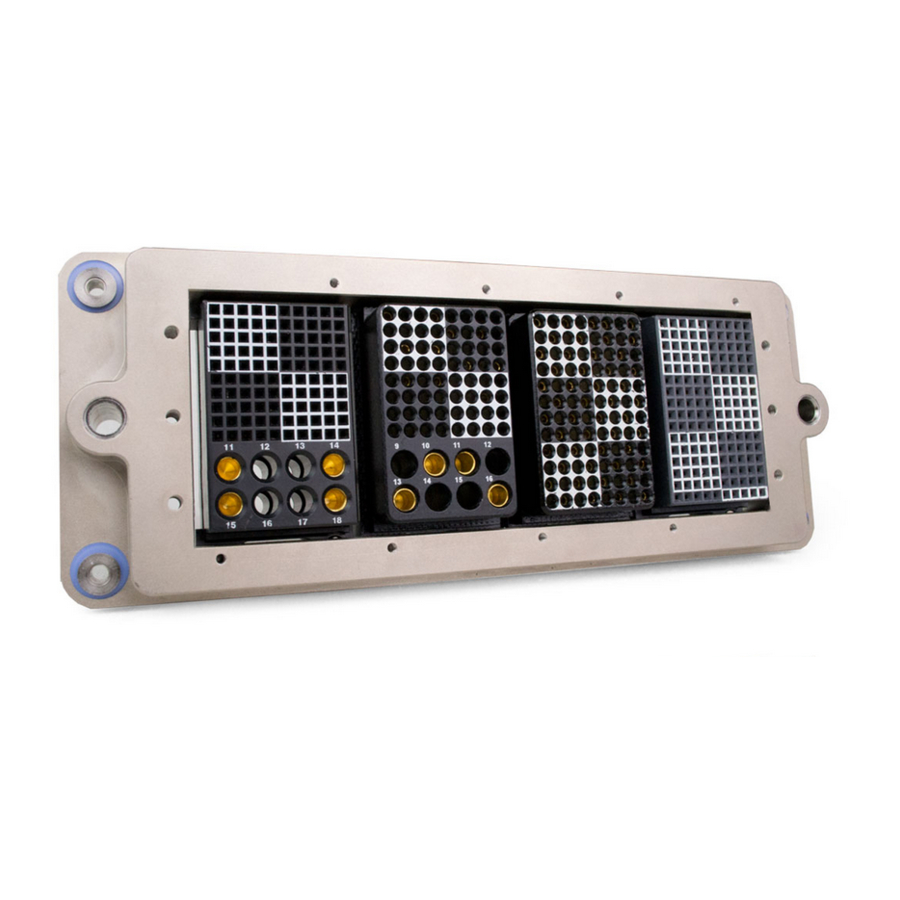
- Page 2 D3/D4 RECEIVER PART IDENTIFICATION PART # 310 131 101 GROOVED FACE OF RECEIVER FRAME The D3/D4 receiver can be configured with three 90 Series modules or four iCon modules depending on the application. This feature is unique to the D3/D4 and is not found elsewhere in the iDock Series.
- Page 3 Modules. GROOVED FACE OF THE ITA FRAME Figure B. Module installation side for the ITA. Both 90 Series module and iCon Modules will be installed on this side. RETURN TO INDEX 03/31/21 For the most current information available, visit vpc.com...
- Page 4 ITA and receiver frame for the full-mated position. The gap will prevent continual contact of the frames upon mating. VPC recommends a maximum gap distance of 0.025” [.635 mm].
- Page 5 INSTRUCTIONS Prepare the mounting surface using the dimensions provided in Figure A. Attach the D3/D4 receiver to the panel with the provided M3 Phillips head screws. Torque the screws to 2 in-lbs [0.23 Nm]. The D3/D4 receiver frame is designed to be used in a modular configuration.
- Page 6 310 131 101 RECEIVER • PART # 410 131 101 ITA • PART # MODULE MOUNTING SCREW The D3/D4 receiver is designed to accept 90 Series TYP. 2 PLCS. Modules and iCon modules. TOOLS REQUIRED 3/32" Allen wrench or balldriver MODULE INSTALLATION (90 SERIES) Locate pin 1 of the module.
- Page 7 D3/D4 MODULE INSTALLATION AND REMOVAL 310 131 101 RECEIVER • PART # 410 131 101 ITA • PART # The D3/D4 receiver is designed to accept 90 Series Modules and iCon modules. TOOLS REQUIRED Phillips Head Screwdriver MODULE INSTALLATION (iCON MODULE) Locate pin 1 of the module.
- Page 8 D3/D4 USER MANUAL D3/D4 ACCESSORIES ● 90 SERIES RECEIVER STRAIN RELIEF ASSEMBLY RECEIVER MODULE (90 SERIES) ● PART # 510 150 115 # 510 109 349 RECEIVER STRAIN RELIEF PLATE (90 SERIES) ● PART Strain relief plates protect your investment. The potential for damage to occur around the area of wire termination is real.
- Page 9 Phillips Head Screwdriver ASSEMBLY INSTRUCTIONS Using a Phillips head screwdriver, fasten the strain relief to the back (wiring) side of the D3/D4 receiver with the two 2-56 provided (Figure A). Torque screws to 2 in-lbs [0.23 Nm]. NOTE: Two 2-56 nuts are included with the strain relief plate;...
Need help?
Do you have a question about the D3 and is the answer not in the manual?
Questions and answers