Advertisement
Quick Links
G12/G12x USER'S MANUAL
TABLE OF CONTENTS
SECTION 1 SLIDE CONFIGURATION
SECTION 8 ITA ENCLOSURES
SECTION 9 ACCESSORIES
SECTION 10 ITA AND RECEIVER ENGAGEMENT
SECTION 11 TROUBLESHOOTING AND PRECAUTIONARY NOTES
Please note that any printed or downloaded User Manuals or Procedure Sheets may not reflect the most current
revisions. The information contained in these materials is subject to change.
For the most current information available, visit www.vpc.com.
10/17/18
Advertisement

Related Manuals for VPC G12


Summary of Contents for VPC G12
-
Page 1: Table Of Contents
SECTION 11 TROUBLESHOOTING AND PRECAUTIONARY NOTES Please note that any printed or downloaded User Manuals or Procedure Sheets may not reflect the most current revisions. The information contained in these materials is subject to change. For the most current information available, visit www.vpc.com. 10/17/18... - Page 2 1.25 FRONT OF RACK Figure A. If dimension C exceeds 1" use the Rack Extender Kit, Part # 310 113 406 for G12 or Part # 310 113 519 for G12x. INSTALLATION Install slides using manufacturer’s instructions. A hard copy is included with the slide kit.
- Page 3 Secure receiver to rack. Figure D. The slides will support 180 pounds. VPC recommends removing the ITA/Fixture when extending the slides for wiring access and maintenance. For the most current information available, visit www.vpc.com...
-
Page 4: Section 2 Slide Configuration Accessories
Attach the cover to the brackets with the fl at head screws. With the extender kit in place, secure the G12 receiver to the mating surface on the extender brackets with #10-32 cap screws. NOTE: The #10-32 cap screws are provided with the G12 receiver. - Page 5 Figure B. The slots on the instrument brackets are designed to accept a strap should you want to secure your chassis. For the most current information available, visit www.vpc.com 10/17/18...
- Page 6 NOTE: The middle section will not go into the outer section until the inner section has been fully installed into the middle section. Tighten the slide mounting screws. MAKE SURE ALL SCREW HEADS HAVE BEEN SECURELY TIGHTENED. ONLY USE 8-32 BUTTON HEAD SCREWS. For the most current information available, visit www.vpc.com 10/17/18...
- Page 7 Attach the cable tray to the slides with #8-32 screws as shown in Figure A. Figure A. The angled side of the cable tray should face the G12/G12x receiver, and with shorter slide kits the cable tray will sit below the lip of the instrument brackets.
- Page 8 PART # 310 113 439 PART # 310 113 439 The Keyboard Tray Kit mounts below the platform on the G12 or G12x receiver. The kit includes a keyboard with touchpad and 58" long USB connector, keyboard tray, and 12" slides.
- Page 9 You will notice the snug fit when tightening the screws. Figure D. The remaining 4 #8-32 button head screws are used to attach the keyboard tray to the slides. For the most current information available, visit www.vpc.com 10/17/18...
-
Page 10: Section 3 Tabletop Configuration
G12/G12x USER’S MANUAL: SECTION 3 TABLETOP CONFIGURATION RECEIVER, G12, 12 MODULE • PART # 310 104 408 / 310 104 409 RECEIVER, G12X, 18 MODULE • PART # 310 104 410 / 310 104 411 / 310 104 422 G12/G12x receivers are shipped with four rubber feet for portable tabletop applications. -
Page 11: Section 4 Tabletop Configuration Accessories
Figure A. Figure A. Rear cover, Part # 310 113 421, is designed to attach to the G12 receiver, Part # 310 104 408/409. Part # 310 113 520 is designed to attach to the G12x receiver, Part # 310 104 410/411. -
Page 12: Section 5 Rack Mount Configuration
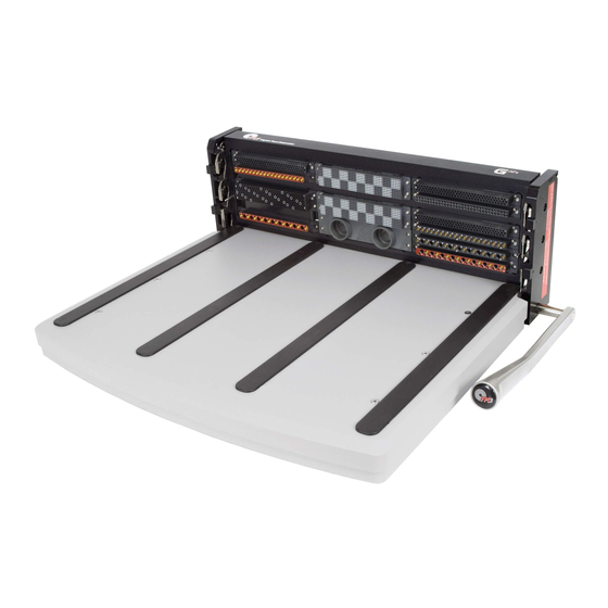
RACK MOUNT CONFIGURATION RECEIVER, G12, 12 MODULE • PART # 310 104 338 The 15” G12 Receiver provides a platform for use with large fi xtures. When this Receiver is fi xed mounted, it can support up to 275 lbs. -
Page 13: Section 6 Rack Mount Configuration Accessories
VIRGINIA PANEL CORPORATION G12/G12x USER’S MANUAL: SECTION 6 RACK MOUNT CONFIGURATION ACCESSORIES RACK EXTENDER KIT, G12 • PART # 310 113 413 The Rack Mount Extender Block Kit is used for mounting to racks with recessed mounting rails. It is made of aluminum with a black anodized fi nish. -
Page 14: Section 7 Handle Removal And Repositioning
G12/G12x USER’S MANUAL: SECTION 7 HANDLE REMOVAL AND REPOSITIONING RECEIVER, G12 • PART # 310 104 325 / 310 104 334 / 310 104 408 / 310 104 409 RECEIVER, G12, LEFT HANDLE • PART # 310 104 356 & 310 104 359 RECEIVER, G12X •... - Page 15 ON THE RECEIVER. THERE IS NO LIMIT TO THE HEIGHT 84.84 OF THE ENCLOSURE. 3.34 Figure A. Enclosures must be flush with the ITA bottom to ensure the proper function of the G12 system. Dimensions shown: [millimeters] inches 10/17/18 For more information visit vpc.com...
- Page 16 VIRGINIA PANEL CORPORATION G12/G12x USER’S MANUAL: SECTION 8 G12X ITA ENCLOSURE ENCLOSURE, G12X , FRONT MOUNT • PART # 410 112 849 ENCLOSURE, G12X, FOR DISCRETE WIRING, 4" X 18" X 12" • PART # 410 112 856 The front mounting G12x enclosure is available to meet your testing needs.
- Page 17 PIN B PIN D SCREW B SCREW D OPEN INSTALLED INSTALLED OPEN OPEN INSTALLED INSTALLED OPEN DETAIL B SCALE 1 : 1.5 DETAIL A SCALE 1 : 1.5 Figure A. Figure B. For the most current information available, visit www.vpc.com 10/17/18...
- Page 18 Pin 1 always be positioned to the left in the receiver and ITA frames. All ITA Modules must match the respective receiver Modules. It is crucial for all modules to be installed properly. G12x Only: The lower four module rows share the same description as on G12 (i.e. A1-A4).
- Page 19 Inspect the matching of modules -power ITA module to mate with power receiver module, etc. Excessive force is needed to engage the Handle • With a typical contact load, approximately 35lbs force is needed to engage the handle. Consult with a VPC application engineer for detailed contact loading information. •...
- Page 20 The foremost precautionary step that needs to be taken is to protect the interface system from damage caused by people (bumping into the receiver/ITA assembly with a box, chair or electronic equipment for example). To prevent this, VPC recommends engaging either the ITA or the receiver Protective Cover to the receiver when not in use.
Need help?
Do you have a question about the G12 and is the answer not in the manual?
Questions and answers