Table of Contents
Advertisement
Quick Links
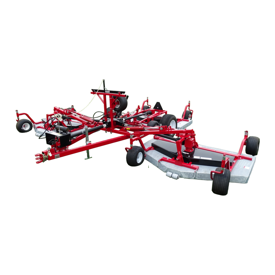
Progressive TD 92 Tri-Deck
PROGRESSIVE TURF EQUIPMENT INC.
137 WEST WILLIAM STREET
SEAFORTH, ONTARIO
CANADA N0K 1WO
PHONE:519-527-1080
TOLL FREE: 800 668-8873
ISSUE DATE: October 2013
Si No Lee Ingles, Pida Ayuda a Alguien Que Se Lo Lea
Para Que le Traduzca Las Medidas de Seguridad
Operator's Manual
and Parts List
Rotary Finishing Mower
Serial No. 13921944 and up
SERIAL # _____________________
WEB:
www.progressiveturfequip.com
P.N.120513
Advertisement
Chapters
Table of Contents

Related Manuals for Progressive Turf Equipment TD 92


Summary of Contents for Progressive Turf Equipment TD 92
- Page 1 Operator’s Manual and Parts List Progressive TD 92 Tri-Deck Rotary Finishing Mower Serial No. 13921944 and up PROGRESSIVE TURF EQUIPMENT INC. 137 WEST WILLIAM STREET SEAFORTH, ONTARIO CANADA N0K 1WO PHONE:519-527-1080 SERIAL # _____________________ TOLL FREE: 800 668-8873 WEB: www.progressiveturfequip.com P.N.120513...
- Page 3 Directive 98/37/EC of the European Parliament and of the Council of 22 June, 1998 on the approximation of the laws of the member states relating to Machinery. The Technical Construction File is maintained at the corporate offices of Progressive Turf Equipment Inc. at the address listed above.
-
Page 5: Table Of Contents
TABLE OF CONTENTS PAGE INTRODUCTION TO THE OWNER …………………………………………….. GENERAL INFORMATION ………………………………… SPECIFICATIONS …………………………………………… SAFETY INSTRUCTIONS ………………………………….. SAFETY DECAL LOCATION ……………………………… SAFETY DECALS ……………………………………… MAINTENANCE SAFETY …………………………………... PROPER BOLT TORQUE ……………………………………. ASSEMBLY INSTRUCTIONS SET – UP INSTRUCTIONS …………………………………… MAIN FRAME ASSEMBLY ………………………………….. INSTALLING PTO SHAFTS …………………………………. -
Page 6: To The Owner
Before you operate this mower, study this manual carefully. It has been prepared to help you do a better and safer job of maintaining your mower. Use only genuine Progressive Turf Equipment Inc. replacement parts. Substitute parts will void the warranty and may not meet the standards required for safe and satisfactory operation of this equipment. -
Page 7: General Information
GENERAL INFORMATION The purpose of this manual is to assist the operator in maintaining and operating Progressive Turf Equipment mowers. Read it carefully. furnishes information and instructions that will help you achieve years of dependable performance. Some information may be general in nature due to unknown and varying conditions. -
Page 9: Specifications
TD92 MACHINE SPECIFICATIONS Cutting Width 22 feet Ground Pressure 7 pounds per square inch Cutting Height ¾” to 5” Deck Flexibility 25° up, 15° down Recommended HP 40 Min – 70 Max Tire To Ground 630 square inches on contact Hydraulics Requires 1 double acting Numbers of Tires 10 on decks, 2 on main frame outlet, all hoses supplied to... - Page 10 SAFETY WORK SAFELY ---- FOLLOW THESE RULES Instructions given with this symbol are for personal safety. Be sure you and your workers follow them. A CAREFUL OPERATOR IS THE BEST INSURANCE AGAINST AN ACCIDENT BEFORE HANDLING ANY EQUIPMENT READ THE OPERATOR’S MANUAL.
- Page 11 SAFETY & MAINTENANCE DECAL LOCATIONS ITEM ITEM DESCRIPTION DESCRIPTION CAUTION - TURNING GREASING SCHEDULE DANGER – READ MANUAL PTO GREASING CAUTION – REPLACE SHIELDS SERIAL PLATE NOTICE – HITCH SETUP MOWER MODEL DANGER - BLADE HAZARD COMPANY NAME WARNING – OEM PARTS DANGER –...
- Page 12 TD92 DECAL LISTING If decals become faded, damaged, or lost, replace immediately. Order decal according to corresponding part number below. Complete decal kits are also available. TD 92 DECAL KIT – 522002 ITEM 3 ITEM 1 ITEM 2 (209113) (521819)
- Page 13 ITEM 13 ITEM 14 (521451) (521455) GREASE POINT DECAL (521014)
-
Page 14: Maintenance Safety
MAINTENANCE SAFETY Never work on mower without safety locks in place, if decks are in raised position. Keep tractor and mower in good operating condition and all safety devices in place. Frequently check blade mounting bolts for tightness. ... -
Page 15: Assembly Instructions
ASSEMBLY INSTRUCTIONS SET - UP INSTRUCTIONS The mower is shipped partially assembled. Assembly will be easier if components are aligned and loosely assembled before tightening hardware. Recommended torque values for hardware are located on page 11. CAUTION Always use personal protection devices such as eye and ear protection during assembly. -
Page 16: Installing Pto Shafts
hitch can be unbolted and rotated 180° to provide different heights. Frame must be level to provide proper flotation. Refer to “Hitching mower to tractor” for more information. Activate hydraulics and cycle a couple times to be sure safety locks work correctly. - Page 17 wrap or hook on short chain. Be sure that when decks are brought into transport position, the safety chain will not bind or pull PTO shield. The Intermediate shaft is installed with the large bell end onto the main gear box.
-
Page 18: Wing Guide Chain
WING GUIDING CHAIN: In some conditions during the unfolding of the mower wings before operating, the wing deck corner pin contacts the end of the supporting plate and does not come to rest on the top of the plate. This is mainly caused by either inadequate lubrication of the wing deck PTO shaft tubes or lowering of decks while not stationary, on level ground. -
Page 19: Operation Of The Mower
OPERATING THE MOWER: A careful and knowledgeable operator is the best insurance against an accident. Allow no riders on any equipment. If tractor is equipped with R.O.P.S., use the seat belt for maximum protection. Make sure that everyone is clear of the tractor and mower before starting the engine or operating. -
Page 20: Hitching Mower To Tractor
HITCHING MOWER TO TRACTOR NOTICE - Attach mower to drawbar only. Drawbar should be adjusted so it is 14” to 15” from the centerline of the draw-pin hole to end of PTO shaft. This is critical for proper PTO shaft operation. -
Page 21: Leveling The Mower & Pto
LEVELLING THE MOWER & PTO For proper mower operation and maximum PTO life, the mower hitch and PTO driveline must be set up correctly. a) When the mower is connected to the tractor, the mower hitch frame “A”, should be as close to level with the ground as possible. b) The connecting hitch “B”... -
Page 22: Checking Pto Length During Turns
CHECK PTO LENGTH DURING TURNS During the mowing operation the tractor should be able to make turns without damage to the driveline. To ensure proper setup check the following conditions: a) With the tractor and mower aligned, and the input PTO straight, turn the shields on the input PTO to check that the holes line up for greasing the input shaft tubes. -
Page 23: Cutting Height Adjustment
CUTTING HEIGHT ADJUSTMENT Mower cutting height adjustment is made by removing lynch pin from the top of each castor stem (square or round) and corner support and moving the spacers either above or below support tube as required for your selected cutting height. -
Page 24: Safety Chain
SAFETY CHAIN It is recommended that the safety chain provided with this mower be attached to the towing vehicle at all times. SAFETY CHAIN Install a safety chain as shown. After attaching the safety chain, make a test run to the left and right for a short distance to check for proper adjustment. -
Page 25: Tires
TIRES Upon receiving your mower, check air pressure in the tires and adjust according to specifications. Mower Deck Tires – 24 PSI Main Frame Tires – 32 PSI CAUTION - Never inflate tires beyond 35 pounds per square inch to seat beads. Inflation beyond 35 PSI pressure before seating the bead may break the bead or even the rim with an explosive force. -
Page 26: Grease Compatibility
An Important Word On Grease Compatibility What Grease Is: -Grease is essentially a distilled petroleum product in the form of mineral oil (or a synthetic) which has a thickening agent such as lithium, calcium, barium, sodium, or aluminum. -Many of the thickeners will work for similar situations, but when mixing greases with different thickeners, one must review compatibility. -
Page 27: Lubrication
Check the properties of the grease you wish to use with your supplier prior to LUBRICATION A properly maintained lubrication schedule will provide a smooth running machine for many years. All pivot locations have grease fittings. The following information shows and describes where all lubrication points are located. -
Page 28: Gearbox Oil Level
only be determined by operator, depending on working conditions in your particular area. GEARBOX OIL LEVELS IMPORTANT! DO NOT OVERFILL! MOWER MUST BE LEVEL WHEN CHECKING GEARBOX OIL LEVEL DECK GEARBOXES: Gearboxes all have an oil level plug located on the side of the gearbox. Oil should reach the bottom of this hole. -
Page 29: Maintenance
MAINTENANCE WARNING - Turn tractor engine off before performing any maintenance. CAUTION - Always use personal protection devices such as eye and ear protectors when performing maintenance functions. WARNING - When completing a maintenance or service function, make sure all safety shields are installed before placing mower in service. -
Page 30: Blade Sharpening
BLADE REMOVAL AND INSTALLATIONS Two, 1/2” X 1 3/4” Grade 5 bolts with lockwashers and nuts hold blade to blade spindle support bar. When changing blades, be sure that these fasteners are in good condition so they will not come loose during operation. -
Page 31: Spindle Inspection
SPINDLE INSPECTION: Spindles are equipped with two roller ball bearings. Adjustment is set by tightening the 1” left hand nut to 60 ft-lbs. torque for proper setting. Periodically inspect blade spindles by grasping blade, and moving from side to side. If any free play is noted, replace or repair. SPINDLE ASSEMBLY REMOVAL: Remove blade from spindle. -
Page 32: Assembly Of Spindles
ASSEMBLY OF SPINDLE: Only use a press that has the ram and bed 100% square to each other. If bearings are not square in housing, bearings will wear out prematurely. Press on outer race when inserting into hub and press on inner race when installing on spindle. -
Page 33: V" Belt Adjustment
“V” BELT ADJUSTMENT: Begin by loosening 4 bolts at the base of the gearbox. By adjusting long threaded bolt, this will slide the gearbox back, tightening the belt. After proper tension is achieved, tighten 4 bolts at base of gearbox. You may have to place a 1/2”... -
Page 34: Hydraulics
HYDRAULICS: The hydraulic system on your Progressive mower is a simple cylinder system used to raise and lower the cutting decks into position. Each cylinder contains a .035 diameter restrictor orifice, which is located on the rod end to slow the speed of travel. -
Page 35: Trouble Shooting
TROUBLE SHOOTING: PROBLEM CAUSE REMEDY Belt Slippage Lack of tension Increase tension Oily Drive Conditions Clean up drive Rapid Belt Wear Belt slippage Increase tension Belt not in proper Place in proper groove groove Belt Squeal Belt Slippage Increase tension Over-heated Bearings Belt Slippage Increase Tension... - Page 37 Parts List TD-92 Effective serial number: 14921923 and up. PN 120513 Issue Date: October 2014 Si No Lee Ingles, Pida Ayuda a Alguien Que Se Lo Lea Para Que le Traduzca Las Medidas de Seguridad...
- Page 38 Use only Genuine Original Equipment Manufacturers (O.E.M.) replacement parts. The use of “will fit” parts may reduce machine performance, void machine warranties and present a safety hazard. Use Genuine OEM parts. Progressive Turf Equipment Inc. 137 West William Street Seaforth, Ontario Canada...
- Page 39 TD92 Parts Manual Maintenance Maintenance should always be performed by a qualified service technician familiar with servicing similar equipment, using good safety and workmanship practices. Always observe proper lock-out procedures when performing any maintenance work. Other than maintaining the blade spindles or blades, always lower all decks before performing maintenance.
- Page 40 PARTS ORDERING GUIDE The following instructions are offered to help eliminate needless delay and error in processing purchase orders for the equipment in this manual. 1. The Parts Section is prepared in logical sequence and grouping of parts that belong to the basic machine featured in this manual. Part Numbers and Descriptions are given to help locate the parts and quantities required.
- Page 41 TD92 Parts Manual Table of Contents SERIAL NUMBER LOCATION...............................II DECK ASSEMBLY ................................2 ..............................2 LADE PINDLE SSEMBLY ................................... 3 LADE PTIONS ................................4 EARBOX SSEMBLY ................................5 SSEMBLY ................................6 SSEMBLY FRAME ASSEMBLY ................................7 ................................. 7 RAME SSEMBLY ................................
-
Page 42: Deck Assembly
TD92 Parts Manual 1 DECK ASSEMBLY 1.1 Blade Spindle Assembly 02/2015... -
Page 43: Blade Options
TD92 Parts Manual 1.2 Blade Options 08/2014... -
Page 44: Gearbox Assembly
TD92 Parts Manual 1.3 Gearbox Assembly 08/2014... -
Page 45: Wing Deck Assembly
TD92 Parts Manual 1.4 Wing Deck Assembly 10/2014... -
Page 46: Rear Deck Assembly
TD92 Parts Manual 1.5 Rear Deck Assembly 10/2014... -
Page 47: Frame Assembly
TD92 Parts Manual 2 FRAME ASSEMBLY 2.1 Frame Assembly 02/2016... -
Page 48: Wing Lift Assembly
TD92 Parts Manual 2.2 Wing Lift Assembly 02/2015... -
Page 49: Tire Assemblies
TD92 Parts Manual 2.3 Tire Assemblies 08/2014... -
Page 50: Hydraulics
TD92 Parts Manual 3 HYDRAULICS 3.1 Hydraulics 08/2014... -
Page 51: Driveline
TD92 Parts Manual 4 DRIVELINE 4.1 Driveline 10/2014... -
Page 52: Input Pto Shaft - Up To Serial #13921935
TD92 Parts Manual 4.2 Input PTO Shaft – Up to Serial #13921935 08/2014... -
Page 53: Input Pto Shaft - Serial # 13921936 & Up
TD92 Parts Manual 4.3 Input PTO Shaft – Serial # 13921936 & Up 08/2014... -
Page 54: Intermediate Pto Shaft - Up To Serial # 13921943
TD92 Parts Manual 4.4 Intermediate PTO Shaft – Up to Serial # 13921943 08/2014... -
Page 55: Intermediate Pto Shaft - Serial # 13921949 & Up
TD92 Parts Manual 4.5 Intermediate PTO Shaft – Serial # 13921949 & Up 08/2014... -
Page 56: Deck Pto Shaft - Up To Serial # 13921943
TD92 Parts Manual 4.6 Deck PTO Shaft - Up to Serial # 13921943 08/2014... -
Page 57: Deck Pto Shaft - Serial # 13921949 & Up
TD92 Parts Manual 4.7 Deck PTO Shaft – Serial # 13921949 & Up... -
Page 58: Deck Gearbox
TD92 Parts Manual 4.8 Deck Gearbox... -
Page 59: Way Gearbox
TD92 Parts Manual 4.9 4 Way Gearbox 08/2014... -
Page 60: Decals
TD92 Parts Manual 5 DECALS 5.1 Safety If decals become faded, damaged, or lost, replace immediately. Order decal according to corresponding Part # below. Complete decal kits are also available. TD-92 DECAL KIT – 522002 209113 209175 521819 DECAL – REPLACE SHIELDS DECAL –... - Page 61 TD92 Parts Manual 521451 521455 DECAL – DANGER – OUTER TUBE DECAL – DANGER – OUTER SHIELD 521014 DECAL – GREASE GUN...
-
Page 62: General Info
TD92 Parts Manual 5.2 General Info...
Need help?
Do you have a question about the TD 92 and is the answer not in the manual?
Questions and answers