Table of Contents
Advertisement
Quick Links
TDR-12 & TDR-15 TRI-DECK
PROGRESSIVE TURF EQUIPMENT INC.
137 WEST WILLIAM STREET
SEAFORTH, ONTARIO
CANADA N0K 1WO
PHONE:519-527-1080
TOLL FREE: 800 668-8873
ISSUE DATE: May 2017
Si No Lee Ingles, Pida Ayuda a Alguien Que Se Lo Lea
Para Que le Traduzca Las Medidas de Seguridad
Operator‟s Manual
and Parts List
Roller Rotary Finishing Mower
TDR-12 Serial No. 1312030 and up
TDR-15 Serial No. 1315121 and up
SERIAL # _____________________
WEB: www.progressiveturfequip.com
P.N.120518
Advertisement
Chapters
Table of Contents

Subscribe to Our Youtube Channel
Related Manuals for Progressive Turf Equipment TDR-12


Summary of Contents for Progressive Turf Equipment TDR-12
- Page 1 Operator‟s Manual and Parts List TDR-12 & TDR-15 TRI-DECK Roller Rotary Finishing Mower TDR-12 Serial No. 1312030 and up TDR-15 Serial No. 1315121 and up PROGRESSIVE TURF EQUIPMENT INC. 137 WEST WILLIAM STREET SEAFORTH, ONTARIO CANADA N0K 1WO PHONE:519-527-1080 SERIAL # _____________________ TOLL FREE: 800 668-8873 WEB: www.progressiveturfequip.com...
-
Page 3: Table Of Contents
TABLE OF CONTENTS __________________________________ PAGE TO THE OWNER: ..........................2 GENERAL INFORMATION: ......................4 MACHINE SPECIFICATIONS ......................5 SAFETY RULES ........................... 6 SAFETY ALERT SYMBOL ....................... 6 HAZARD SERIOUSNESS LEVEL ....................6 GENERAL SAFETY PRECAUTIONS ....................7 POWER UNIT SAFETY ........................7 OPERATING EQUIPMENT SAFELY .................... -
Page 5: To The Owner
It has been prepared to help you do a better and safer job of maintaining your mower. Use only genuine Progressive Turf Equipment Inc. replacement parts. Substitute parts will void the warranty and may not meet the standards required for safe and satisfactory operation of this equipment. -
Page 7: General Information
GENERAL INFORMATION The purpose of this manual is to assist the operator in maintaining and operating Progressive Turf Equipment mowers. Read it carefully. It furnishes information and instructions that will help you achieve years of dependable performance. Some information may be general in nature due to unknown and varying conditions. -
Page 8: Machine Specifications
2.90 5.8 8.75 Height (Acres/hr) TDR-15 3.75 7.5 11.3 Assumes no stops or overlap Length 14 ft. Weight TDR-12 3500 lbs Blade Spindles TDR-15 3725 lbs 9 1/4” Cutting Ground Clearance DECK FRAME “A” Drive PTO shaft to right angle gear box Hollow structural steel tubing with supports driving 2-“B”... -
Page 9: Safety Rules
This section of the Operator’s Manual details a number of safety rules pertaining to the operation and maintenance of Progressive Turf Equipment mowers. In order to minimize risks and promote safety at all times, these rules must always be followed and obeyed. -
Page 10: General Safety Precautions
GENERAL SAFETY PRECAUTIONS The operator of this machine must have sufficient knowledge and instructions in the care and operation of this mower and the power unit being used before he / she uses the machine. Do not allow unauthorized persons or children to operate the machine. Do not allow riders on the machine. -
Page 11: Operating Equipment Safely
OPERATING EQUIPMENT SAFELY Never allow persons to stand between power unit and mower while backing power unit up to hitch the mower. Before hitching mower to power unit, place transmission in neutral, set park brake, and turn engine off. Remove the ignition key. ... -
Page 12: Maintenance Safety Precautions
Ensure transport locks are securely engaged before transporting mower with wings in raised position. Clean reflectors, Slow Moving Vehicle sign and lights before transporting. Use power unit hazard lights. Before disconnecting from power unit, always lower equipment to the ground, place controls in neutral, set park brake, turn engine off, and wait for all moving parts to stop. -
Page 13: Welding And Grinding Work Precautions
WELDING AND GRINDING WORK PRECAUTIONS IMPORTANT! A fire extinguisher should be easily accessible during all welding work. Welding repairs are to be performed by a trained welder with proper service instructions. Know the material to be welded and select the correct welding procedure and materials (electrodes, rods, wire) that will provide a weld metal strength equivalent to the parent material. -
Page 14: Safety Chain
SAFETY CHAIN It is recommended that the safety chain provided with this mower be attached to the towing vehicle at all times. Install a safety chain as shown. After attaching the safety chain, make a test run to the left and right for a short distance to check for proper adjustment. Readjust to eliminate a loose or tight chain TRANSPORTING MOWERS When traveling on public roadways, use flashing amber lights and... -
Page 15: Tires
TIRES Upon receiving your mower, check air pressure in the tires and adjust according to specifications. TIRE TYPE RECOMMENDED TIRE PRESSURE (PSI) MAIN FRAME TIRES 32 PSI Never inflate tires beyond 35 pounds per square inch (PSI) to seat beads. Inflation beyond 35 PSI pressure before seating the bead may break the bead or even the rim with an explosive force. -
Page 16: Safety & Maintenance Decal Locations
SAFETY & MAINTENANCE DECAL LOCATIONS ITEM ITEM DESCRIPTION DESCRIPTION DANGER – READ MANUAL MOWER MODEL FRONT DECK HEIGHT CAUTION - TURNING CAUTION – REPLACE REAR DECK HEIGHT SHIELDS SAFETY SIGN – INNER TUBE COMPANY NAME SAFETY SIGN - OUTER DANGER - BLADE HAZARD GUARD WARNING –... -
Page 17: Decal Listing
DECAL LISTING If decals become faded, damaged, or lost, replace immediately. Order decal according to corresponding part # below. Complete decal kits are also available. TDR-12 DECAL KIT – 524002 TDR-15 DECAL KIT – 524004 ITEM 2 – A & C ITEM 2 –... - Page 18 ITEM 14 (209139) ITEM 12 ITEM 13 (If Equipped) (If Equipped) (209139) (209123) ITEM 14 ITEM 15 (521451) (210237) ITEM 19 ITEM 18 (209182) (521455) ITEM 17 ITEM 16 (210239) (210238) GREASE POINT DECAL (521014)
-
Page 19: Operating The Mower
OPERATING THE MOWER: A careful and knowledgeable operator is the best insurance against an accident. Allow no riders on any equipment. If tractor is equipped with R.O.P.S., use the seat belt for maximum protection. Make sure that everyone is clear of the tractor and mower before starting the engine or operating. -
Page 20: Hitching Mower To Tractor
HITCHING MOWER TO TRACTOR Attach mower to drawbar only. Drawbar should be adjusted so it is 14” to 15” from the center line of the draw pin hole to end of PTO shaft. This is critical for proper PTO shaft operation. ... -
Page 21: Levelling The Mower & Pto
LEVELLING THE MOWER & PTO For proper mower operation and maximum PTO life, the mower hitch and PTO driveline must be setup correctly. a) When the mower is connected to the tractor, the mower hitch frame “A”, should be as close to level with the ground as possible. b) The connecting hitch “B”... -
Page 22: Installing Pto Shafts
INSTALLING PTO SHAFTS The three identical PTO shafts are used to drive the mower decks. Each PTO shaft will have one end designated a tractor end. This end should be hooked up to the main gearbox. The PTO shafts from the two wing decks must be timed when mounted to the gearbox. See photo below. -
Page 23: Check Pto Length During Turns
CHECK PTO LENGTH DURING TURNS The Pro-Flex 120 mower features a hose support which also serves the function to limit the steering angle of the mower without damage to components. In proper operation, the tractor tire should contact the hose support first if the operator attempts to turn too sharp without damage to the drive-line. -
Page 24: Cutting Height Adjustment
CUTTING HEIGHT ADJUSTMENT There are four height adjusters per mowing deck. Each adjuster (located in each corner of the deck) must be adjusted to the same height to ensure a smooth even cut. A wrench for this purpose is provided. In addition, each deck must be adjusted the same so that a level cut is obtained across the whole cutting width of the mower. -
Page 25: Pro Lift-N-Turntm System
Pro Lift-N-TurnTM SYSTEM Your TDR-15 is equipped with the system. This feature allows the Pro Lift-N-Turn® operator to lift all three cutting decks just off the ground to negotiate a tight turn without shutting down the PTO. Using this system will eliminate roller drag and scuffing while turning at the end of a row. -
Page 26: Machine Maintenance
MACHINE MAINTENANCE MAINTENANCE SAFETY Never work on mower without safety locks in place, if decks are in raised position. Keep tractor and mower in good operating condition and all safety devices in place. Frequently check blade mounting bolts for tightness. ... -
Page 27: Grease Compatibility
GREASE COMPATIBILITY All greases are not compatible. Grease incompatibility will decrease the lubrication ability of the grease, and can cause premature part failure. Grease can have mineral or synthetic base oils and thickening agents such as lithium, calcium, barium, sodium, or aluminum What We Use: - Progressive uses Shell Gadus S2 V220 2 - This grease has:... -
Page 28: Lubrication
SHAFTS WITH BLACK SHIELDS SHAFTS WITH YELLOW SHIELDS BLADE SPINDLE GREASING: TDR-12 (Up to SN 1412037*) TDR-15 (Up to SN 1415136*) The top bearing on all spindle assemblies has a shield only. This allows grease to exit and relieves any pressure build up inside spindle housing, when greasing. Greasing of blade spindles should continue until grease can be seen exiting between the top bearing. -
Page 29: Gearbox Oil Levels
GEARBOX OIL LEVELS: IMPORTANT! DO NOT OVERFILL! MOWER MUST BE LEVEL WHEN CHECKING GEARBOX OIL LEVEL DECK GEARBOXES: Gearboxes all have an oil level plug located on the side of the gearbox. Oil should reach the bottom of this hole. If oil level is low, add oil through top plug hole of casing until oil just starts to flow out of side oil level hole. -
Page 30: Blade Servicing
BLADE SERVICING Always observe proper lock-out procedures when performing any maintenance work including changing or servicing the blades. Always remove and retain the ignition switch key, ensure parking brake is engaged, and block and or support machine using equipment designed for the task. Be sure deck safety locks are engaged when working on decks in the raised position. - Page 31 BLADE REMOVAL AND INSTALLATION A 1” diameter pilot centers the blade on the spindle with two 1/2” grade 5 fasteners. When changing blades, be sure that pilot is properly seated in the blade and the blade lies flat on the spindle Eroded bar.
- Page 32 BLADE SHARPENING Use gloves when handling mower blades. Blades can be very sharp. When sharpening blades, be sure material removed is equal on both sides of the blade. Unbalanced blades will cause excessive vibration leading to cracks in machine components. ...
-
Page 33: Spindle Service
SPINDLE SERVICE NOTE: TDR-15 and TDR-12 series mowers have been equipped from the factory with two styles of blade spindles: Up to SN 1415136 (TDR-15) / SN 1412036 (TDR-12) Blade spindles are factory equipped with greasable bearings. These spindles are identified by a grease fitting in the center of the drive pulley. -
Page 34: Assembly Of Spindle
ASSEMBLY OF SPINDLE: Only use a press that has the ram and bed 100% square to each other. If bearings are not square in housing, bearings will wear out prematurely. Press on outer race when inserting into hub and press on inner race when installing on spindle. If bearings are being changed, be sure to check bearing spacer for wear. -
Page 35: V" Belt Adjustment
“V” BELT ADJUSTMENT: Begin by loosening 4 bolts at the base of the gearbox. Adjusting long threaded bolt slides the gearbox back, tightening belt. After proper tension is achieved, tighten 4 bolts at base of gearbox. You may have to place a ½” nut under the head of the long threaded bolt to increase your adjustment length. -
Page 36: Hydraulics
The first 24 to 48 hours of operation is the belt “run in” period. To ensure satisfactory belt performance, belt tension should be checked during this time period. HYDRAULICS: The hydraulic system on your Progressive mower is a simple cylinder system used to raise and lower the cutting decks into position. -
Page 37: Trouble Shooting
TROUBLE SHOOTING: PROBLEM CAUSE REMEDY Belt slippage Lack of tension Increase tension oily drive conditions Clean up drive Rapid belt wear Belt slippage Increase tension belt not in proper Place in proper groove groove Belt squeal Belt slippage Increase tension Over-heated bearings Belt slippage Increase Tension... - Page 39 TDR-12 & TDR-15 TDR15 TDR12 Effective serial numbers: TDR-15: 1315121 and up. TDR-12: 1312030 and up. Si No Lee Ingles, Pida Ayuda a Alguien Que Se Lo Lea P.N. 120518 Para Que le Traduzca Las Medidas de Seguridad Issue Date: Jan 2018...
-
Page 40: Serial Number Location
Use only Genuine Original Equipment Manufacturers (O.E.M.) replacement parts. The use of “will fit” parts may reduce machine performance, void machine warranties and present a safety hazard. Use Genuine OEM parts. Progressive Turf Equipment Inc. 137 West William Street Seaforth, Ontario Canada... - Page 41 TDR 12 & 15 Parts Manual Maintenance Maintenance should always be performed by a qualified service technician familiar with servicing similar equipment, using good safety and workmanship practices. Always observe proper lock-out procedures when performing any maintenance work. Other than maintaining the blade spindles or blades, always lower all decks before performing maintenance.
- Page 42 PARTS ORDERING GUIDE The following instructions are offered to help eliminate needless delay and error in processing purchase orders for the equipment in this manual. 1. The Parts Section is prepared in logical sequence and grouping of parts that belong to the basic machine featured in this manual. Part Numbers and Descriptions are given to help locate the parts and quantities required.
- Page 43 REASABLE – M ........................3 LADE PINDLE SSEMBLY AINTENANCE – TDR 15 W & R ) ........................4 SSEMBLY – TDR-12 ............................5 SSEMBLY & B ..............................6 OLLERS EARINGS ................................7 EARBOX SSEMBLY FRAME ASSEMBLY ................................8 ................................. 8...
-
Page 44: Deck Assembly
TDR 12 & 15 Parts Manual 1 DECK ASSEMBLY 1.1 Blade Spindle Assembly – Greaseable TDR 15 up to Serial # 1415136 TDR 12 up to Serial # 1412036 03/2015... -
Page 45: Blade Spindle Assembly - Maintenance Free
TDR 12 & 15 Parts Manual 1.2 Blade Spindle Assembly – Maintenance Free TDR 15 Serial # 1415137 & up TDR 12 Serial # 1412038 & up 02/2015... -
Page 46: Deck Assembly - Tdr 15 Wing & Rear (All)
TDR 12 & 15 Parts Manual 1.3 Deck Assembly – TDR 15 Wing & Rear (All) 02/2017... -
Page 47: Wing Deck Assembly - Tdr-12
TDR 12 & 15 Parts Manual 1.4 Wing Deck Assembly – TDR-12 02/2017... -
Page 48: Deck Rollers & Bearings
TDR 12 & 15 Parts Manual 1.5 Deck Rollers & Bearings TDR-15 (All) - TDR-12 (Rear Deck) ROUND ROLLER SHAFTS TDR-15 - UP TO SN 1715184 TDR 12 - UP TO SN 1612057 HEX ROLLER SHAFTS TDR-15 - SN – 1715185 & UP TDR 12 - SN –... -
Page 49: Gearbox Assembly
TDR 12 & 15 Parts Manual 1.6 Gearbox Assembly 02/2015... -
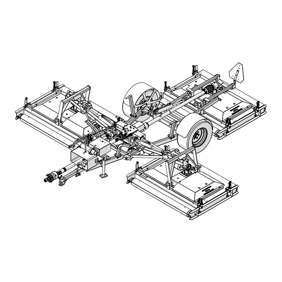
Page 50: Frame Assembly
TDR 12 & 15 Parts Manual 2 FRAME ASSEMBLY 2.1 Frame Assembly 04/2016... -
Page 51: Lift Assembly
TDR 12 & 15 Parts Manual 2.2 Lift Assembly 02/2015... -
Page 52: Deck Standoffs & Locks
TDR 12 & 15 Parts Manual 2.3 Deck Standoffs & Locks TDR15 up to Serial #1515150 TDR12 up to Serial #1512043 05/2015... -
Page 53: Deck Standoffs & Locks
TDR 12 & 15 Parts Manual 2.4 Deck Standoffs & Locks TDR15 Serial #1515151 & Up TDR12 Serial #1512044 & Up 05/2015... -
Page 54: Wing Lock Assemblies
TDR 12 & 15 Parts Manual 2.5 Wing Lock Assemblies TDR15 up to Serial #1515148 TDR12 up to Serial #1512043 02/2015... -
Page 55: Wing Lock Assemblies
TDR 12 & 15 Parts Manual 2.6 Wing Lock Assemblies TDR15 Serial #1515149 & up TDR12 Serial #1512044 & up 02/2015... -
Page 56: Wheel Assemblies
TDR 12 & 15 Parts Manual 2.7 Wheel Assemblies 07/2014... -
Page 57: Hydraulics
TDR 12 & 15 Parts Manual 3 HYDRAULICS 3.1 Hydraulics 02/2015... -
Page 58: Driveline
TDR 12 & 15 Parts Manual 4 DRIVELINE 4.1 Driveline 06/2015... -
Page 59: Input Pto Shaft
TDR 12 & 15 Parts Manual 4.2 Input PTO Shaft All B Models D Models – Serial #1515149 and up 07/2014... -
Page 60: Input Pto Shaft
TDR 12 & 15 Parts Manual 4.3 Input PTO Shaft TDR15 D Model – Up to Serial #1515148 TDR15 D Model – Optional on Serial #1515149 & up 04/2015... -
Page 61: Intermediate Pto Shaft
TDR 12 & 15 Parts Manual 4.4 Intermediate PTO Shaft 07/2014... -
Page 62: Wing Deck Pto Shaft
TDR 12 & 15 Parts Manual 4.5 Wing Deck PTO Shaft TDR 12 UP TO SERIAL #1512043 TDR 15 UP TO SERIAL #1515148 02/2015... -
Page 63: Wing Deck Pto Shaft - Current
TDR 12 & 15 Parts Manual 4.6 Wing Deck PTO Shaft - Current TDR 12 SERIAL #1512044 & up TDR 15 SERIAL #1515149 & up 06/2015... -
Page 64: Rear Deck Pto Shaft
TDR 12 & 15 Parts Manual 4.7 Rear Deck PTO Shaft 09/2014... -
Page 65: Way Gearbox
TDR 12 & 15 Parts Manual 4.8 4 - Way Gearbox 07/2014... -
Page 66: Deck Gearbox - Standard Rotation
TDR 12 & 15 Parts Manual 4.9 Deck Gearbox – Standard Rotation 02/2015... -
Page 67: Deck Gearbox - Reverse Rotation
TDR 12 & 15 Parts Manual 4.10 Deck Gearbox – Reverse Rotation 02/2015... -
Page 68: Decals
TDR 12 & 15 Parts Manual 5 DECALS 5.1 Safety If decals become faded, damaged, or lost, replace immediately. Order decal according to corresponding part number below. Complete decal kits are also available. TDR-15 DECAL KIT - 524004 TRD-12 DECAL KIT - 524002 209171 DECAL –... - Page 69 TDR 12 & 15 Parts Manual PROGRESSIVE PROGRESSIVE TDR-15 TDR-12 ROLLER MOWER ROLLER MOWER 209126 209127 TDR-12 ROLLER MOWER DECAL TDR-15 ROLLER MOWER DECAL 210237 521455 SAFETY SIGN – OUTER GUARD DECAL – DANGER – OUTER TUBE 521451 DECAL DANGER – INNER SHAFT...
-
Page 70: Notes
TDR 12 & 15 Parts Manual 5.2 Notes __________________________________________________________________________________________ __________________________________________________________________________________________ __________________________________________________________________________________________ __________________________________________________________________________________________ __________________________________________________________________________________________ __________________________________________________________________________________________ __________________________________________________________________________________________ __________________________________________________________________________________________ __________________________________________________________________________________________ __________________________________________________________________________________________ __________________________________________________________________________________________ __________________________________________________________________________________________ __________________________________________________________________________________________ __________________________________________________________________________________________ __________________________________________________________________________________________ __________________________________________________________________________________________ __________________________________________________________________________________________ __________________________________________________________________________________________ __________________________________________________________________________________________ __________________________________________________________________________________________ __________________________________________________________________________________________ __________________________________________________________________________________________ __________________________________________________________________________________________ __________________________________________________________________________________________ __________________________________________________________________________________________ __________________________________________________________________________________________...
Need help?
Do you have a question about the TDR-12 and is the answer not in the manual?
Questions and answers