Advertisement
Quick Links
MODEL NO.:PH08-SB/PH08-SSB
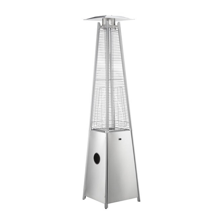
TOWER PATIO HEATER
OPERATION INSTRUCTIONS
MODEL NO.:PH08-SB/PH08-SSB
FOR OUTDOOR USE ONLY.
KEEP THESE INSTRUCTIONS FOR FUTURE REFERENCE.
554HPSQRSS, 554HPSQRSTL, 554HPSQRBZ, 554HPSQRBLK
FOR OUTDOOR USE ONLY.
KEEP THESE INSTRUCTIONS FOR FUTURE REFERENCE.
05/2020
1
FOR OUTDOOR USE ONLY.
KEEP THIS MANUAL FOR FUTURE REFERENCE.
TABLE OF CONTENTS
Package Contents..................................................
Safety Information................................................
Assembly Instructions...........................................
Operation Instructions..........................................
Troubleshooting.....................................................
Equipment Limited Warranty................................
2-3
3-5
6-12
13-16
17
18
1
Advertisement

Related Manuals for Backyard Pro Patio Series


Summary of Contents for Backyard Pro Patio Series
-
Page 1: Table Of Contents
MODEL NO.:PH08-SB/PH08-SSB TOWER PATIO HEATER OPERATION INSTRUCTIONS MODEL NO.:PH08-SB/PH08-SSB TABLE OF CONTENTS FOR OUTDOOR USE ONLY. KEEP THESE INSTRUCTIONS FOR FUTURE REFERENCE. Package Contents..........Safety Information..........Assembly Instructions........... 6-12 Operation Instructions.......... 13-16 Troubleshooting............. Equipment Limited Warranty........ 554HPSQRSS, 554HPSQRSTL, 554HPSQRBZ, 554HPSQRBLK FOR OUTDOOR USE ONLY. -
Page 2: Package Contents
PACKAGE CONTENTS PACKAGE CONTENTS Reflector Damper Upper Support Wireguard Glass Tube Middle plate Side Panel Control box Lower Support Front Panel Base QUANTITY Reflector Damper Upper Support Wireguard Glass Tube Middle plate Side Panel Lower Support Front Panel Base Control box... -
Page 3: Safety Information
HARDWARE CONTENTS Screw Stability Ring Fixing M3/16 (if available) Bracket Knob attach to Qty. 1 Qty. 4 Qty. 1 the regarding parts AA Battery Wheels Rubber Ring Qty. 1 Qty. 1 set Qty. 1 SAFETY INFORMATION This manual contains important information about the assembly, operation, and maintenance of this patio heater. - Page 4 s recommended by the instructions. (CO) during the combustion process. This product e adequate clearances around air openings designed to produce extremely minute, non-hazard combustion chamber. amounts of CO if used and maintained in accordan use the heater in spaces which do or may with all warnings and instructions.
- Page 5 SAFETY INFORMATION WARNING WARNING California Proposition 65 • This product is fueled by propane gas. Propane gas Combustion by-products produced when using this product is invisible, odorless, and flammable. An odorant contain chemicals known to the State of California to cause is normally added to help detect leaks and can be cancer, birth defects, and other reproductive harm.
-
Page 6: Assembly Instructions
ASSEMBLY INSTRUCTIONS ASSEMBLY INSTRUCTIONS 1. Attach 1 set wheels(FF) to the base(J), if needed. 1. Attach 1 set wheels(FF) to the base(J), if needed. 2. Attach the stability ring(DD) to the 2. Attach the stability ring(DD) to the base base (J), if available. (J),if avalable. - Page 7 ASSEMBLY INSTRUCTIONS ASSEMBLY INSTRUCTIONS 3. Unsrew any pre installed (M3/16) 3. Unscrew any pre-installed (M3/16) screws(AA) first. Assemble the four screws (AA) first. Assemble the four lower supports (H) to the base (J) and lower supports (H) to the base (J) and middle plate(F)using the (M3/16) screws (AA).
- Page 8 ASSEMBLY INSTRUCTIONS ASSEMBLY INSTRUCTIONS 5. Unscrew(M3/16) 4pcs screws from the 5. Unscrew (M3/16) 4pcs screws from the bottom of the middle plate(F). Install an bottom of the middle plate (F). Install AA battery(EE) into the control box. an AA battery (EE) into the control Assemble the control box(K) onto the bottom of middle plate using the (M3/16) screws.
- Page 9 ASSEMBLY INSTRUCTIONS ASSEMBLY INSTRUCTIONS 7. Carefully install the glass tube (E) by lifting 7. Carefully install the glass tube (E) by up and inserting through the center hole in lifting up and inserting through the the upper plate. Ensure the rubber ring(GG) To aid in installation center hole in the upper plate.
- Page 10 ASSEMBLY INSTRUCTIONS ASSEMBLY INSTRUCTIONS 9. Attach the three side panels (G) to the 9. Attach the three side panels (G) to the heater using the (M3/16) screws (AA). heater using the (M3/16) screws (AA). Note : 1. M3/16 screws from Step 3 unscrewed 1.
- Page 11 ASSEMBLY INSTRUCTIONS ASSEMBLY INSTRUCTIONS . Propane Only-Proper Hose Connection. 11. Propane Only-Proper Hose Connection. Connect Connect the hose to the hose connector in the control box. the hose to the hose connector in the control box. WARNING! Ensure the hose does not contact any high temperature surfaces, or it may melt and leak causing WARNING! Ensure the hose does not contact fire.
- Page 12 ASSEMBLY INSTRUCTIONS ASSEMBLY INSTRUCTIONS A dented, rusted or damaged propane cylinder may be and propane Installation Code, CSA B149.1, or hazardous and should be checked by your cylinder propane storage and handling code, B149.2. supplier. Never use a propane cylinder with a damaged valve connection.
-
Page 13: Operation Instructions
OPERATION INSTRUCTIONS UCTIONS OPERATION INSTRUCTIONS Leak Check LEAK CHECK WARNING WARNING WARNING • Perform all leak tests outdoors. outdoors. • Perform all leak tests outdoors. • Extinguish all open flames. mes. • Extinguish all open flames. • NEVER leak test when smoking. n smoking. - Page 14 OPERATION INSTRUCTIONS WARNING • CARBON MONOXIDE HAZARD • For outdoor use only. Never use inside house, or other unventilated or enclosed areas. This heater consumes air (oxygen). Do not use in unventilated or enclosed areas to avoid endangering your life. Caution: Do not attempt to operate until you have read and understand all General Safety Information in this manual and all assembly is complete and leak checks have been performed.
- Page 15 OPERATION INSTRUCTIONS OPERATION INSTRUCTIONS 4. If the pilot lights, keep control knob pressed for 15 seconds then 3.Check for pilot flame through glass tube. If pilot does turn the control knob to ‘LOW’. not light, turn control knob to ‘OFF’ position wait two 5.
- Page 16 OPERATION INSTRUCTIONS STORAGE: Between uses: • Turn the control knob to “OFF” position. • Turn LPG cylinder to “OFF” position. • Store heater upright in an area sheltered away from weather conditions (such as rain, sleet, hail, snow). • If desired, cover heater to protect exterior surfaces and to help prevent dust and debris collecting in air passages.
-
Page 17: Troubleshooting
TROUBLESHOOTING PROBLEM POSSIBLE CAUSE CORRECTIVE ACTION Cylinder valve is closed Open valve Blockage in orifice or pilot Clean or replace orifice or tube pilot tube Pilot won’t light Open gas line and bleed it (pressing control knob in) for Air in gas line Note: Heater operates at not more than 1 - 2 minutes reduced efficiency below... -
Page 18: Equipment Limited Warranty
EQUIPMENT LIMITED WARRANTY Backyard Pro warrants its equipment to be free from defects in material and workmanship for a period of 30 days. This is the sole and exclusive warranty made by Backyard Pro covering your Backyard Pro brand equipment. A claim under this warranty must be made within 30 days from the date of purchase of the equipment.
Need help?
Do you have a question about the Patio Series and is the answer not in the manual?
Questions and answers