Yaesu FTDX10 Operation Manual
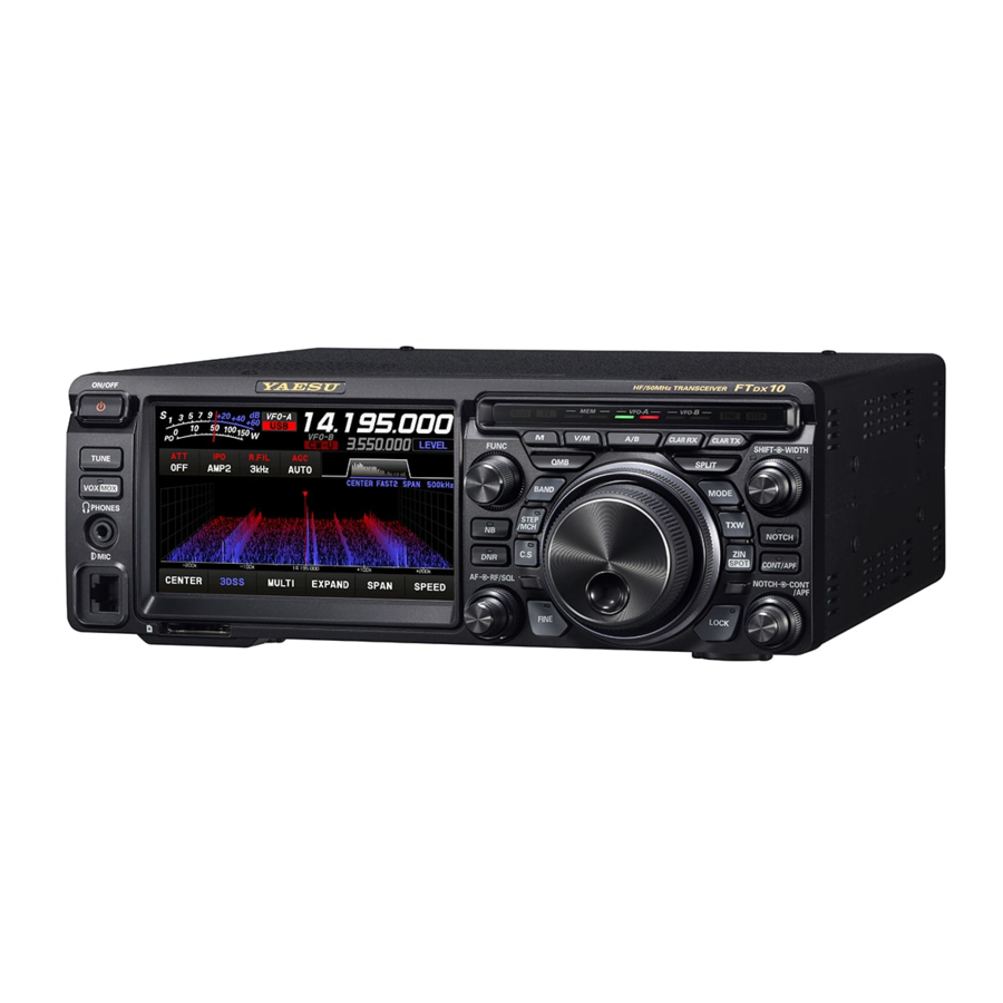
Hf/50mhz transceiver
Hide thumbs
Also See for FTDX10:
- Technical supplement (121 pages) ,
- Reference manual (26 pages) ,
- Quick start manual (2 pages)
Table of Contents
Advertisement
Quick Links
Advertisement
Table of Contents

Related Manuals for Yaesu FTDX10


Summary of Contents for Yaesu FTDX10
- Page 1 Operation Manual...
- Page 2 The FTDX10 is a leading-edge transceiver with a number of new and exciting features, some of which may be unfamiliar to you. In order to gain the most enjoyment and operating efficiency from the FTDX10, we recommend that you read this manual in its entirety, and keep it handy for reference as you explore the many capabilities of this new transceiver.
-
Page 3: Table Of Contents
Table of Contents General Description ........4 Adjusts the VOX Delay Time ....... 32 Safety Precautions .........6 Adjusts the VOX anti-trip sensitivity .... 33 Accessories & Options ........8 Adjusting the Noise Blanker Level ....34 Supplied Accessories ........8 Adjusting the Noise Attenuation ....34 Available options .......... - Page 4 FC-40 External Automatic Antenna Tuner TFT Screen ..........66 (for Wire Antenna) ......... 108 Text Message Programming on Interconnections to FTDX10 ...... 108 FH-2 Remote Controller ......66 Setup the transceiver ........ 109 Text Input ............. 66 Tuning Operation ........109 On-The-Air RTTY Text Message ....
-
Page 5: General Description
General Description Hybrid SDR configuration inherited from the FTDX101 series In addition to the narrow band SDR receiver that boasts awesome basic performance, the FTDX10 has a hybrid SDR configuration utilizing an integrated direct sampling SDR receiver, which permits visualization of the entire band spectrum in real time. - Page 6 Reliable High-output Final Amplifier Stage FTDX10 power amplifier utilizes a pair of RD70HUP2 transistors in a push-pull RF arrangement that deliv- ers 100 watts of low-distortion, high-quality transmitter power.
-
Page 7: Safety Precautions
Safety Precautions Note beforehand that the company shall not be liable for any damages suffered by the customer or third parties in using this product, or for any failures and faults that occur during the use or misuse of this prod- uct, unless otherwise provided for under the law. - Page 8 Do not allow metallic objects such as wires Refrain from using headphones and ear- and water to get inside the product. phones at a loud volume. This may result in fire, electric shock and equip- Continuous exposure to loud volumes may result ment failure.
-
Page 9: Accessories & Options
Accessories & Options Supplied Accessories Hand Microphone SSM-75E DC Power Cord Spare Fuse (25A) 6.3 mm 3-contact Plug • Operation Manual • World Map • Sticker Available options • Hand Microphone (equivalent to the supplied microphone) SSM-75E • Reference Microphone •... -
Page 10: Installation And Interconnections
Construct the antenna and coaxial cable, or use a suitable antenna tuner, to maintain the impedance presented to the FTDX10 antenna connector for an SWR of 1.5 or less. Careful preparation of the anten- na and/or tuner will permit maximum performance, and protect the transceiver from damage. -
Page 11: Microphone, Headphone, Key, Keyer And Fh-2 Connections
Microphone, Headphone, Key, Keyer and FH-2 Connections φ3.5mm DOWN UP +5V MIC GND MIC PTT GND FAST (as viewed from front panel) Remote Control Keypad FH-2 (option) Key-up voltage is approximately +5.0 V DC, and key-down current is approximately 3 mA. -
Page 12: Linear Amplifier Interconnections
Linear Amplifier Interconnections Be sure that both the FTDX10 and VL-1000 are turned OFF, and then follow the installation recommendations contained in the bellow illustration. • VL-1000 Linear Amplifier Interconnections • Refer to the VL-1000 Operating Manual for details regarding amplifier operation. -
Page 13: Display Connections
Operate the transceiver from a remote location. Use the optional LAN unit “SCU-LAN10” to connect the FTDX10 to a LAN or the Internet, then use the PC control software that can be downloaded from the Yae- su website. In addition to the basic remote operation of the transceiver, the LAN unit supports monitoring the various scope displays, so you can operate comfortably. -
Page 14: Rear Panel
This 8-pin output jack is used for connection to the FC-40 External Automatic Antenna Tuner. By plugging the FH-2 Remote Control Keypad into RX D (BAND A) this jack, direct access to the FTDX10 CPU is pro- +13V OUT TX GND vided for control functions of the contest memory keying, and also frequency and function control. - Page 15 RS-232C This 9-pin serial DB-9 jack permits external computer control of the FTDX10. Connect a serial cable here and to the RS-232C COM port on your personal computer (no external interface is re- quired). SERIAL OUT SERIAL IN This 13-pin jack may be connected to an external device.
-
Page 16: Ssm-75E Microphone Switches
SSM-75E Microphone Switches MUTE PTT Switch MUTE Key Switches Transmit/Receive. While pressing the MUTE key, the receiver audio Press to transmit and release to receive. from the speaker will be muted. DWN / UP Key Microphone The [UP]/[DWN] keys may also be used to manual- Speak into the microphone in a normal tone of ly scan the frequency upward or downward. -
Page 17: Display Indications
Display Indications It operates as an S meter in receive. In transmit, select the desired meter from: PO, COMP, ALC, VDD, ID, and SWR. Displays the current operation mode. In VFO mode, “VFO-A” or “VFO-B” is displayed. In memory mode, the type and chan- nel number of the recalled memory are displayed. - Page 18 Meter Display Operation MODE Display S-Meter Displays the current operating mode. When touched the operation mode selection screen is displayed. Touch the desired operation mode to select it. RF power Output When the meter display screen is touched, the transmit meter selection screen is shown (the default default setting is “PO”).
-
Page 19: Keyboard Frequency Entry
Frequency Display (VFO-A) Frequency Display (VFO-B) Exhibits the transmit and receive frequencies of Exhibits the transmit and receive frequencies of VFO-A. VFO-B. When the clarifier function is active, the offset fre- • Keyboard Frequency Entry quency is displayed. 1. Touch the “Hz” area of the frequency display. •... - Page 20 Operation of the display [FUNC] knob Displays the multiple functions that may be operated when the [FUNC] knob is pressed. Normally, it is recommended to adjust the level of the spectrum scope with the [LEVEL] knob. The last used function is recalled when the [FUNC] knob is pressed. Therefor you can easily call up and then set a function by turning the [FUNC] knob.
-
Page 21: Select The Roofing Filter
Filter Function Display Displays the passband status of the DSP filter. The operation of WIDTH, SHIFT, NOTCH, CONTOUR etc. can be observed. Passband status of DSP filter (SHIFT, WIDTH) State of NOTCH State of CONTOUR The current roofing filter bandwidth is displayed as a blue line below the filter function display. SSB Mode CW Mode RTTY Mode... - Page 22 Information displayed on the scope screen Scope screen information CENTER : The receive frequency is always shown at the center of the screen and spectrum display. The band spectrum is shown within the range set by “SPAN”. The CENTER mode is convenient for monitoring the signal activity around the operating frequency.
-
Page 23: Att (Attenuator)
Important Receiver Settings The status of various operations that are important during receive, are shown at the bottom of the display. To change a setting, touch the appropriate location on the display. Important setting items when receiving • ATT (Attenuator) •... -
Page 24: Agc (Automatic Gain Control)
AGC Menu se- stant. lections until you are thoroughly familiar with the ● AGC can be set for each operation band. performance of the FTDX10. ● The “AUTO” selection mode selects the opti- mum receiver-recovery time for the reception mode. -
Page 25: Center/Cursor/Fix
The frequency span is shown on the horizontal X axis, the vertical Y axis depicts the signals and their strengths, and the time is represented on the receding Z axis. The FTDX10 operator can intuitively grasp the band and signal conditions at any instant. -
Page 26: Fix
• FIX • 3DSS To use Fixed Mode, enter the start frequency of the Switch between the 3DSS display and the waterfall scope. display. The display will change each time it is touched: 3DSS type Display area start frequency Marker* (Reception Frequency) Marker* (Transmit Frequency) Waterfall type Current display mode (FIX) -
Page 27: Expand
• EXPAND • SPEED The display area of the scope screen may be ex- Sets the Scope Display sweep speed. After touch- panded vertically. ing, select the desired speed. Touch to expand the display. Touch again to return to the original. Normal Display SLOW1 : sweep speed Slow... -
Page 28: Level
Set with the FUNC knob Operate the [FUNC] knob to make the following settings related to the display. LEVEL : Adjust the LEVEL of the scope for the best image on the screen. PEAK : Adjust the color density with respect to the signal level on the scope screen in 5 steps (LV1 to LV5). -
Page 29: Marker
• MARKER • Adjust contrast Displays markers that indicates the position of the Adjust the contrast of the TFT display. current receive and the transmit frequencies in the Press the [FUNC] knob then touch [CONTRAST], spectrum. and then turn the [FUNC] knob to adjust the con- Press the [FUNC] knob then touch [MARKER] to trast. -
Page 30: Other Display Settings
Other display settings • Screen Saver • Inputting the Call Sign A Screensaver, to prevent burning of the TFT Registered call signs names, and characters can screen will operate after a set time, if no trans- be displayed on the opening screen when the ceiver function is operated. - Page 31 About TFT Displays FTDX10 utilizes a TFT liquid-crystal display. Although TFT liquid-crystal displays are made using very precise technology, they are prone to de- velop dead pixels (dark dot) or pixels that are always on (bright dot). Please understand that such phenomena do not constitute product defects or malfunctions.
-
Page 32: Led Indications
LED Indications Displays the transmit/receive status of the transceiver, and the MPVD ring “FINE” and “STEP”. RX Indicator TX Indicator Fine Tuning Indicator Memory Mode VFO-A VFO-B STEP Indicator RX/TX RX/TX RX/TX Indicators Indicators Indicators BUSY: This indicator illuminates when the squelch VFO-B RX/TX Indicators opens. -
Page 33: Front Panel Controls & Switches
While VOX is activated, the LED TUNE inside this key glows orange. 1. Press the [VOX] key. This is the ON/OFF switch for the FTDX10 Auto- VOX feature is activated matic Antenna Tuner. 2. Without pressing the PTT switch, speak into the Press the [TUNE] key briefly to activate the antenna microphone in a normal voice level. -
Page 34: Adjusts The Vox Anti-Trip Sensitivity
2. Touch [ANTI VOX] . 3. Rotate the [FUNC] knob to prevent receiver au- case to lower the front of the FTDX10. dio from activating the transmitter (via the micro- phone). Pressing this key engages the PTT (Push to Talk) circuit to activate the transmitter. -
Page 35: Adjusting The Noise Blanker Level
• Adjusting the Noise Attenuation 1. Press the [FUNC] knob. The FTDX10 includes an effective IF Noise Blank- 2. Select [OPERATION SETTING]→[GENERAL] er, which can significantly reduce noise caused by →[NB REJECTION]. automotive ignition systems. 3. Rotate the [FUNC] knob to set the noise attenu- The NB function can be operated individually for ation (10dB / 30dB / 40dB). -
Page 36: Adjusting The Dnr Level
• Adjusting the DNR Level • Switching the operation of the [RF/SQL] knob Turn the [FUNC] knob to DNR Level adjust the DNR Level. 1. Press the [FUNC] knob. 2. Select [OPERATION SETTING]→[GENERAL] → [RF/SQL VR]. 3. Select “RF” or “SQL”. 4. - Page 37 MPVD ring (MULTI PURPOSE VFO OUTER DIAL) The frequency can be changed in 10 times the frequency steps of the main dial. Select the MPVD operation by touching one of the keys: Frequency; Mode; CLAR (Clarifier); Select Memory channnels; STEP Tuning; or C.S (Custom Select).
-
Page 38: Rx Clarifier
Clarifier • TX Clarifier The transmit frequency can be changed without The clarifier is used to adjust the transceiver re- moving the receive frequency of the transceiver. ceive frequency to match the other station transmit Normally, the clarifier is used to move only the re- frequency and improve the audio;... -
Page 39: How To Assign Functions
STEP/MCH C.S (Custom Select) STEP By simply pressing the [C.S] key, the MPVD ring operates in the function that has been assigned to Press the [STEP/MCH] key to turn ON the LED of the [C.S] key (see below) (default setting is LEV- the [STEP/MCH] key and “STEP”... - Page 40 MAIN dial The MAIN dial sets the operating frequency. Rotate the MAIN dial knob to tune within the band, and begin normal operation. ● Pressing the [STEP/MCH] key engages the “STEP tuning (default setting: 10 kHz)” selection. ● The amount of frequency change depends on the operation mode (default setting: see table below).
- Page 41 BAND (Operating Band Selection) MODE (Operating Mode Selection) Touch the display to select Touch the display to select Press the [BAND] key, the operation band selection Press the [MODE] key or touch the operation mode screen appears on the display, so touch the desired area, the operation mode selection screen appears band.
-
Page 42: Quick Split Operation
SPLIT • Direct input of offset frequency The offset can be set to a frequency other than A powerful capability of the FTDX10 is its flexibil- 5kHz with the on-screen keyboard. ity in Split Frequency operation using the VFO-A and VFO-B frequency registers. This makes the 1. - Page 43 NOTCH (IF NOTCH Filter) The performance of the IF Notch filter is shown The IF NOTCH filter is a highly effective system in Figure “A", where the effect of rotation of the that allows you to slice out an interfering beat note [NOTCH] knob is depicted.
-
Page 44: Adjust The Gain Of The
CONT/APF Refer to Figure “B”, this illustrates an “indentation” of the Contour filter in the center of the passband. CONT (Contour) Counterclockwise rotation (to the left) of the The Contour filter system provides a gentle per- [CONT/APF] knob causes the notch to move to- turbation of the IF filter passband. - Page 45 SHIFT, WIDTH Outer Knob (WIDTH) The IF WIDTH tuning system allows you to vary the Press and hold the [SHIFT] knob to reset the shift width of the DSP IF passband, to reduce or elimi- frequency set by the [SHIFT] knob and the band- nate interference.
- Page 46 Using IF SHIFT and WIDTH Together The IF SHIFT and Variable IF WIDTH features together form a very effective interference-fighting fil- tering system. For example, in Figure “A", you can see how in- Desired Signal Desired Signal Desired Signal terference has appeared both on the high and low sides of the desired signal.
-
Page 47: Voice Communications (Ssb And Am)
Voice Communications (SSB and AM) When transmitting in SSB or AM mode The FTDX10 transmit audio circuit can be set to the optimum operating level by individually adjusting the input and output gains of the microphone amplifier. The AMC (Automatic Microphone Gain Control) regulates the microphone audio so that distortion does not oc- cur, even if excessive audio is input. -
Page 48: Speech Processor
Speech Processor ● Setting of maximum transmission output The maximum transmit power can be set for each The FTDX10 Speech Processor is designed to of the HF Bands, the 50MHz band and the AM increase “talk power” by increasing the average mode. -
Page 49: Parametric Microphone Equalizer
Parametric Microphone Equalizer The FTDX10 includes a unique Three-Band Parametric Microphone Equalizer that provides precise, in- dependent control over the low, mid and treble ranges in the voice waveform. One group of settings may be utilized when the AMC or speech processor is Off, and an alternate group of settings when the AMC or Speech Processor is On (SSB mode only). - Page 50 Parametric Gain 3-Stage Parametric Equalizer Adjustments (Speech Processor: “OFF”) PRMTRC EQ1 FREQ (Low) “100” (Hz) - “700” (Hz) / OFF Center Frequency PRMTRC EQ2 FREQ (Mid) “700” (Hz) - “1500” (Hz) / OFF PRMTRC EQ3 FREQ (High) “1500” (Hz) - “3200” (Hz) / OFF PRMTRC EQ1 LEVEL (Low) “-20”...
-
Page 51: Voice Memory
Voice Memory The Voice Memory capability of the FTDX10 may be used to store and replay often repeated messages. The Voice Memory includes five memories. The Voice Memory may be operated from the Display Panel, or from the optional FH-2 Remote Control Keypad, which plugs into the rear panel REM jack. -
Page 52: Record The Received Audio
Record the received audio You can record and play the received audio on the SD memory card. Record and play of the received audio may be operated from the Display Panel, or from the optional FH-2 Remote Control Keypad, which plugs into the rear panel REM jack. •... -
Page 53: Adjustable Receiver Audio Filter
Adjustable Receiver Audio Filter The FTDX10 incorporates an adjustable receiver audio filter, that affords precision control of the lower and upper audio ranges independently. 1. Press the [FUNC] knob. 2. Select [CW SETTING] for CW mode and [RA- DIO SETTING] for other modes. -
Page 54: Change The Sound Quality Of The Received Audio
Change the sound quality of the received audio You can change each of the high, mid, and low frequencies of the received audio to your liking. It can be set for each mode. 1. Press the [FUNC] knob. 2. Select [CW SETTING] for CW mode and [RA- DIO SETTING] for other modes. -
Page 55: Using The Automatic Antenna Tuner
SWR at the antenna feed point. • The ATU in the FTDX10 is designed to match impedances within the range of 16.5 Ohms to 150 Ohms, cor- responding to an SWR of 3:1 or less on the HF amateur bands (6 m amateur band: 25 Ohms to 100 Ohms, corresponding to an SWR of 2:1 or less). - Page 56 Figure 1 depicts a situation where normal tuning via the ATU has been successfully completed, and the tuning data has been stored in the ATU memory. The antenna system SWR as seen by the transmitter is shown. In Figure 2, the operator has changed frequency, and the “HI-SWR” icon has appeared. The operator presses and holds in the TUNE button for one second to begin impedance matching using the ATU.
-
Page 57: Cw Mode Operation
“CW FREQ DISPLAY” (page 96). 1. Before starting, connect the key cable to the ● By connecting the FTDX10 to a computer, rear panel KEY jack. CW can be operated using free or commer- 2. Set the operating mode to CW-U. -
Page 58: Cw Decode
CW Decode Alphanumeric Morse code can be decoded and displayed as text on the TFT Panel. Interfering signals, noise, propagation phasing, and code inaccuracy, may prevent accurate message copy. 1. Set the operating mode to CW. 2. Press the [FUNC] knob, and then touch [CW SPEED] and turn the [FUNC] knob to closely match the speed of the received CW signal. -
Page 59: Setting Of The Electronic Keyer
Keyer speed can be adjusted by rotating the The configuration of the Electronic Keyer may be [FUNC] knob. customized for the FTDX10. This permits utiliza- tion of Automatic Character Spacing (ACS), if de- Press [FUNC], then touch [CW SPEED], and ro- sired. -
Page 60: Contest Memory Keyer
Contest Memory Keyer The CW message capability of the FTDX10 may be controlled either from the Transceiver Front Panel, or with the optional FH-2 Remote Control Keypad, which plugs into the rear panel REM jack. • Message Memory Five CW memory channels capable of retaining 50 characters each are available (using the PARIS stan- dard for characters and word length). -
Page 61: Checking The Cw Memory Contents
• Checking the CW Memory Contents • On-The-Air CW Message Playback 1. Press the [FUNC] knob. 1. Press the [FUNC] knob. 2. Touch [BK-IN] to turn it “OFF”. 2. Touch [BK-IN] to turn it “ON”. 3. Touch [MONI LEVEL] and then turn the When using FH-2, go to step 5. -
Page 62: Text Memory
MEMORY 4 and MEMORY 5 in factory de- fault. Contest Number Programming MEMORY 4: DE FTDX10 K } MEMORY 5: R 5NN K } Use this process when starting a new con- test, or if somehow the numbering gets out 6. -
Page 63: Checking The Cw Memory Contents
• Checking the CW Memory Contents • On-The-Air CW Message Playback 1. Set the operating mode to CW. 1. Set the operating mode to CW. 2. Touch [BK-IN] to turn it “OFF”. 2. Touch [BK-IN] to turn it “ON”. 3. Touch [MONI LEVEL] and then turn the When using FH-2, go to step 5. -
Page 64: Fm Mode Operation
FM Mode Operation Repeater Operation Tone Squelch Operation The FTDX10 may be operated on 29 MHz and 50 The “Tone Squelch” may be activated to keep the MHz repeaters. receiver silent until an incoming signal modulated with a matching CTCSS tone is received. The 1. -
Page 65: Rtty (Fsk) Operation
RTTY (FSK) Operation The FTDX10 is equipped with a RTTY decode function. The RTTY signal may be easily synchronized by aligning the marker displayed on the TFT screen. Mark frequency (2125 Hz), SHIFT width (170 Hz), and baudot code (US) can be changed in the Setting Menu. -
Page 66: Rtty Decode
3. The setting is concluded when 1 second have elapsed after making the level adjustment. CQ CQ CQ DE W6DXC W6DXC W6DXC K YAESU FTDX10 Displays text entered into the RTTY sending memory. -
Page 67: Rtty Text Memory
The following texts are programmed to the MEMORY 4 and MEMORY 5 in factory default. 4. Touch [1] through [5] key, depending on which MEMORY 4: DE FTDX10 K RTTY Text Memory Register message is to MEMORY 5: R 5NN K be transmitted. -
Page 68: Data (Psk) Operation
DATA (PSK) Operation The FTDX10 PSK Decode Feature supports both BPSK and QPSK with error correction functions. Easily synchronize PSK by aligning the marker on the TFT display screen. Connecting to a Personal Computer Connect the transceiver and a PC with a commercially available USB cable (A-B) to perform PSK data communications using commercially available software and freeware. -
Page 69: Psk Decode
Note that text will no longer be displayed for weak CQ CQ CQ DE W6DXC W6DXC W6DXC K YAESU FTDX10 signals if the level is increased too much. 3. The setting is concluded when 1 second have Displays content written to the elapsed after making the level adjustment. -
Page 70: Psk Text Memory
MEMORY 4 and MEMORY 5 in factory de- 4. Touch [1] through [5] key, depending on which fault. PSK Text Memory Register message you MEMORY 4: DE FTDX10 K wish to transmit. The programmed message MEMORY 5: R 5NN K will be transmitted on the air. -
Page 71: Memory Operation
Memory Operation • Erasing Memory Channel Data The contents written to the memory channel may • Memory Storage be erased. 1. Set the frequency, mode, and status, as de- sired. 1. Press the [M] key. 2. Press the [M] key. The memory channel list will be displayed. -
Page 72: Check Memory Channel Status
• Check Memory Channel Status • Labeling Memories Before programming a memory channel, the Alphanumeric labels (“Tags”) may be appended to current contents of that channel may be verified memory channels, to aid in recollection of the chan- without the danger of over-writing the channel. nel’s use (such as a club name, a location etc.). -
Page 73: Displaying The Memory Tag
• Displaying the Memory Tag or rotate the [FUNC] knob to select [BACK] and press the [FUNC] knob to return to the The “Frequency display” or “Alpha tag display” state of step 1. format may be selected. “X” lights up for channels for which “SKIP” is 1. -
Page 74: 60-Meter (5 Mhz) Band (U.s. And U.k. Version Only)
• 60-Meter (5 MHz) Band Memory Groups (U.S. and U.K. Version only) Memory channels may be listed into as many Memory channels (U.S. version: “5-01” through as six convenient groups, for easy identification “5-10”, U.K. version: “5-01” through “5-07”) are and selection. -
Page 75: Vfo And Memory Scanning
VFO and Memory Scanning Either the VFO or the memory channels of the FTDX10 may be scanned, and the receiver will halt scan- ning on any frequency with a signal strong enough to open the receiver squelch. In the SSB/CW and SSB-based Data modes, the decimal points in the frequency display area will blink and the scanner will slow down (but does not stop). -
Page 76: Programmable Memory Scan (Pms)
Programmable Memory Scan (PMS) To limit scanning (and manual tuning) to a particular frequency range, the Programmable Memory Scan- ning (PMS) feature utilizes nine special-purpose memory pairs (“M-P1L/M-P1U through M-P9L/ M-P9U). The PMS feature is especially useful in helping to observe any operating sub-band limits which apply to your Amateur license class. -
Page 77: Other Functions
Other Functions Band Stack Operation TOT (Time Out Timer) The FTDX10 employs a triple band-stack VFO The “Time-Out Timer” (TOT) shuts the transmitter selection technique that permits storing up to OFF after continuously transmitting for the pro- three favorite frequencies and modes onto each grammed time. -
Page 78: Operation On Alaska Emergency Frequency: 5167.5 Khz (U.s. Version Only)
The FTDX10 is capable of transmitting and re- ceiving on 5167.5 kHz under such emergency conditions. Use the Setting Menu to activate the Alaska Emergency Frequency feature: 2. -
Page 79: Using The Sd Card
6. Touch the screen to end formatting. • Note that Yaesu shall not be liable for any 7. Touch [BACK] several times to return to nor- damages suffered as a result of data loss or mal operation. -
Page 80: Menu Data
• Saving Memory data and Setting Menu data The Memory Channel data, and the Setting Menu data can be saved to the SD Card: 1. Press the [FUNC] knob. 5. Enter the file name (maximum 15 characters) 2. S e l e c t [ E X T E N S I O N S E T T I N G ] → [ S D on the file name input screen. -
Page 81: Reading Memory And Set Menu Data
• Reading Memory and Set Menu data • Display the SD Card Information The Memory and Setting Menu data saved on the The memory free space of the SD card may be SD card may be read to the Transceiver. checked: 1. -
Page 82: Setting Menu
Setting Menu The Menu system of the FTDX10 provides extensive customization capability. The transceiver functions can be tailored for the most demanding operators. The Setting Menus are grouped into five specific utili- zation categories. Comprehensive settings such as: Transmit & Receive, Interference Reduction, Memory, Scan, etc. - Page 83 Menu Function Available Settings (Default: Bold) RADIO SETTING MODE SSB AF TREBLE GAIN -20 - 0 - 10 AF MIDDLE TONE GAIN -20 - 0 - 10 AF BASS GAIN -20 - 0 - 10 AGC FAST DELAY 20 - 300 - 4000 (20msec/step) AGC MID DELAY 20 - 1000 - 4000 (20msec/step) AGC SLOW DELAY...
- Page 84 Menu Function Available Settings (Default: Bold) AF BASS GAIN -20 - 0 - 10 AGC FAST DELAY 20 - 160 - 4000 (20msec/step) AGC MID DELAY 20 - 500 - 4000 (20msec/step) AGC SLOW DELAY 20 - 1500 - 4000 (20msec/step) PSK TONE 1000 / 1500 / 2000 (Hz) DATA SHIFT (SSB)
- Page 85 Menu Function Available Settings (Default: Bold) CW WAVE SHAPE 1 / 2 / 4 / 6 (msec) CW FREQ DISPLAY DIRECT FREQ / PITCH OFFSET PC KEYING OFF / DAKY / RTS / DTR QSK DELAY TIME 15 / 20 / 25 / 30 (msec) CW INDICATOR OFF / ON KEYER...
- Page 86 MPVD STEPS PER REV. 250 / 500 DISPLAY SETTING DISPLAY MY CALL Max 12 characters (FTDX10) MY CALL TIME OFF / 1 / 2 / 3 / 4 / 5 (sec) SCREEN SAVER OFF / 15 / 30 / 60 (min)
- Page 87 AGC SLOW DELAY RADIO SETTING Function: Sets the AGC-SLOW DELAY voltage - MODE SSB - decay characteristics for SSB mode. Available Values: 20 - 4000msec AF TREBLE GAIN Default Setting: 3000msec Description: Sets the AGC voltage decay char- Function: Sets the amount of gain in the treble acteristics in 20msec steps after the range of the received audio.
- Page 88 SSB MOD SOURCE RADIO SETTING Function: Selects the transmit audio input jack in - MODE AM - the SSB mode by pressing the [VOX/ MOX] key. AF TREBLE GAIN Available Values: MIC / REAR Default Setting: MIC Function: Sets the amount of gain in the treble Description: range of the received audio.
- Page 89 AGC SLOW DELAY AM MOD SOURCE Function: Sets the AGC-SLOW DELAY voltage Function: Selects the transmit audio input jack decay characteristics for AM mode. in the AM mode by pressing the [VOX/ Available Values: 20 - 4000msec MOX] key. Default Setting: 4000msec Available Values: MIC / REAR Description: Sets the AGC voltage decay char- Default Setting: MIC...
- Page 90 AGC SLOW DELAY RADIO SETTING Function: Sets the AGC-SLOW DELAY voltage - MODE FM - decay characteristics for FM mode. Available Values: 20 - 4000msec AF TREBLE GAIN Default Setting: 1500msec Description: Sets the AGC voltage decay char- Function: Sets the amount of gain in the treble acteristics in 20msec steps after the range of the received audio.
- Page 91 MIC GAIN Function: Sets the microphone gain for the FM Function: Sets the Repeater Shift Direction. mode. Available Values: - / SIMP / + Available Values: MCVR / 0 - 100 Default Setting: SIMP Default Setting: MCVR Description: Description: Shifts to the lower frequency offset. MCVR: Adjust the microphone gain (0 - 100) us- SIMP: The frequency does not shift.
- Page 92 AGC SLOW DELAY RADIO SETTING Function: Sets the AGC-SLOW DELAY voltage - MODE PSK/DATA - decay characteristics for PSK/DATA mode. AF TREBLE GAIN Available Values: 20 - 4000msec Default Setting: 1500msec Function: Sets the amount of gain in the treble Description: Sets the AGC voltage decay char- range of the received audio.
- Page 93 TX BPF SEL RADIO SETTING Function: Selects the audio passband of the DSP - MODE RTTY - modulator on the DATA mode. Available Values: 50-3050 / 100-2900 / 200-2800 AF TREBLE GAIN 300-2700 / 400-2600 (Hz) Default Setting: 300-27000 Hz Function: Sets the amount of gain in the treble range of the received audio.
- Page 94 AGC SLOW DELAY HCUT SLOPE Function: Sets the AGC-SLOW DELAY voltage Function: Sets the slope of the high-frequency decay characteristics for RTTY mode. cutoff audio filter in RTTY mode. Available Values: 20 - 4000msec Available Values: 6dB/oct / 18dB/oct Default Setting: 1500msec Default Setting: 6dB/oct Description: Sets the AGC voltage decay char- RTTY OUT LEVEL...
- Page 95 RADIO SETTING RADIO SETTING - ENCDEC PSK - - ENCDEC RTTY - PSK MODE RX USOS Function: Selects the operation mode of the PSK Function: Enables/Disables the RX USOS fea- mode. ture. Available Values: BPSK / QPSK Available Values: OFF / ON Default Setting: BPSK Default Setting: ON Description:...
- Page 96 AGC SLOW DELAY CW SETTING Function: Sets the AGC-SLOW DELAY voltage - MODE CW - decay characteristics for CW mode. Available Values: 20 - 4000msec AF TREBLE GAIN Default Setting: 1500msec Description: Sets the AGC voltage decay char- Function: Sets the amount of gain in the treble acteristics in 20msec steps after the range of the received audio.
- Page 97 CW BK-IN TYPE QSK DELAY TIME Function: Sets the CW brake-in function. Function: Sets the time delay before transmitting Available Values: SEMI / FULL the keying signal. Default Setting: SEMI Available Values: 15 / 20 / 25 / 30 msec Default Setting: 15 msec Description: Description: The QSK mode delay time before...
- Page 98 NUMBER STYLE CW SETTING Function: Selects the contest number “Cut” for- - KEYER - mat for an imbedded contest number. Available Values: 1290 / AUNO / AUNT / A2NO / KEYER TYPE A2NT / 12NO / 12NT Default Setting: 1290 Function: Selects the desired keyer operation Description: Abbreviates numbers “One”, “Two”, mode for the device connected to the...
- Page 99 CW MEMORY 3 CW SETTING Function: Selects the registration method for the - DECODE CW - contest keyer “CW MEMORY 3”. Available Values: TEXT / MESSAGE CW DECODE BW Default Setting: TEXT Description: Function: Selects the bandwidth of the AFC fea- TEXT: Use the optional FH-2 or the touch ture.
- Page 100 232C TIME OUT TIMER OPERATION SETTING Function: Time-Out-Timer for an RS-232C com- - GENERAL - mand input. Available Values: 10 / 100 / 1000 / 3000 (msec) NB WIDTH Default Setting: 10 msec Description: Sets the Time-Out-Timer countdown Function: Sets the duration of the noise blanking time for an RS-232C command in- pulse to match various types of noise put.
- Page 101 QUICK SPLIT FREQ MIC SCAN RESUME Function: Selects the amount the frequency is Function: Sets the Scan Resume function. offset when the Quick Split feature is Available Values: PAUSE / TIME enabled. Default Setting: TIME Available Values: -20 - 0 - 20kHz (1 kHz/step) Description: Default Setting: 5kHz PAUSE: During automatic scanning, the scanner...
- Page 102 OPERATION SETTING OPERATION SETTING - RX DSP - - TX AUDIO - APF WIDTH AMC RELEASE TIME Function: Sets the bandwidth of the Audio Peak Function: AMC level adjustment tracking speed Filter. setting Available Values: NARROW / MEDIUM / WIDE Available Values: FAST / MID / SLOW Default Setting: MEDIUM Default Setting: MID...
- Page 103 PRMTRC EQ2 LEVEL P PRMTRC EQ1 FREQ Function: Sets the gain for the middle range of Function: Sets the center frequency of the low the 3 Band Parametric Microphone range for the 3 Band Parametric Mi- Equalizer. crophone Equalizer when the AMC or Available Values: -20 - 0 - 10 (dB) speech processor is activated.
- Page 104 P PRMTRC EQ2 LEVEL P PRMTRC EQ3 BWTH Function: Sets the gain for the middle range of Function: Sets the width (“Q”) for the high range the 3 Band Parametric Microphone of the 3 Band Parametric Microphone Equalizer when the AMC or speech Equalizer when the AMC or speech processor is activated.
- Page 105 EMERGENCY FREQ TX OPERATION SETTING Function: Enables TX/RX operation on the Alas- - TX GENERAL - ka Emergency Channel, 5167.5kHz. Available Values: OFF / ON HF MAX POWER Default Setting: OFF Description: When this Menu Item is set to “ON”, Function: Sets the transmit RF power output of the spot frequency of 5167.5 kHz will...
- Page 106 Available Values: Up to 12 alphanumeric charac- Available Values: 5 / 10 (Hz) ters Default Setting: 10 Default Setting: FTDX10 Description: Set characters to be displayed on RTTY/PSK DIAL STEP the power ON opening screen. Function: Setting of the Main dial knob tuning MY CALL TIME speed in the RTTY and PSK mode.
- Page 107 DISPLAY SETTING DISPLAY SETTING - SCOPE - - EXT MONITOR - EXT DISPLAY Function: Sets the resolution of Spectrum Scope Function: Video signal output setting of the EXT- display. DISPLAY terminal on the rear panel. Available Values: HIGH / MID / LOW Available Values: OFF / ON Default Setting: HIGH Default Setting: OFF...
- Page 108 SD Memory Card. Function: Memory reset FIRMWARE UPDATE Description: Only the information stored in the Function: Update the firmware of the FTDX10. Memory Channel is initialized (all Description: When a new firmware update for erased). the FTDX10 is available, go to the The contents of the memory channel “M-01”...
-
Page 109: Optional Accessories
After mounting the FC-40, connect the cables from the FC-40 to the ANT and TUNER jacks on the rear panel of the FTDX10 Transceiver. Turn OFF the external power supply switch and the FTDX10 power supply switch first before connecting the cables. -
Page 110: Setup The Transceiver
50-ohm impedance to the FTDX10’s ANT jack. Before tuning can begin, the FTDX10 must be configured to recognize that the FC-40 is being used. Configuration is done using the Setting Menu Mode: 1. -
Page 111: Active-Tuning Antenna System (Atas-120A)
ATAS-120A is a multi-band auto-tuning antenna that can be used in the amateur bands from the HF band to the UHF band (7/14/21/28(29) /50/144/430). Using the active tuning mechanism, tuning can be carried out automatically by the control signal from FTDX10. Please refer to the ATAS-120A Operating Manual for the assembly and installation of ATAS-120A. -
Page 112: Remote Control Switches
FH-2 Remote Control Switches With the optional remote-control keypad FH-2 voice messages may be recorded and transmitted (Voice Memory). The FH-2 is also the control of the Contest Memory Keyer during CW operation. ● SSB / AM / FM modes have five voice memory channels (90 seconds each) for storage and playback, of voice recordings (page 50). -
Page 113: Cw Narrow Filter Xf-130Cn
• Do not use an improper screw for mounting the MHG-1! An improper screw may cause a “short circuit” to the internal circuitry, causing serious damage. Screw the Carrying Handle to the FTDX10 using the supplied screws. Handle end Mounting Screw... -
Page 114: Resetting The Microprocessor
Resetting the Microprocessor Memory channels, setting menus, and various settings can be initialized and returned to their factory de- faults. EXTENTION SETTING FUNC knob RESET DONE 1. Display the reset item selection screen. Press the [FUNC] knob → touch [EXTENTION SETTING] → touch [RESET] 2. -
Page 115: Specifications
Specifications General Tx Frequency Range: 1.8MHz - 54MHz (Amateur bands only) 70MHz - 70.5MHz (UK Amateur bands only) Rx Frequency Range: 30kHz - 75MHz (operating) 1.8MHz - 29.699999MHz (specified performance, Amateur bands only) 50MHz - 53.999999MHz (specified performance, Amateur bands only) 70MHz - 70.499999MHz (specified performance, UK Amateur bands only) Emission Modes: A1A (CW), A3E (AM), J3E (LSB, USB), F3E (FM),... -
Page 116: Receiver
Receiver Circuit Type: Double Superheterodyne Intermediate Frequencies: 1st 9.005MHz 2nd 24kHz Sensitivity (typ): SSB/CW (2.4kHz, 10dB S+N/N) 1.8MHz - 30MHz 0.16µV (AMP2 “ON”) 50MHz - 54MHz 0.125µV (AMP2 “ON”) 70MHz - 70.5MHz 0.16µV (AMP2 “ON”) AM (BW: 6kHz, 10dB S+N/N, 30% modulation @400Hz) 0.5MHz - 1.8MHz 7.9µV 1.8MHz - 30MHz... -
Page 117: Index
Index 3DSS ............... 25 Display connections ......... 12 5 MHz Band ............. 73 Display Indications ........... 16 60-Meter (5 MHz) Band ........73 DNR ..............34 DWN key ............15 A/B ..............35 About TFT Displays ......... 30 Electronic Keyer ..........58 ACC .............. - Page 118 MCH ..............38 Memory Groups ..........73 Safety Precautions ..........6 Memory Operation ........... 70 Scan Skip Setting ..........72 Memory Scanning ..........74 Scope Display Setting ........24 Meter Display ........... 17 Screen capture ..........77 MIC ..............33 Screen Saver ...........
-
Page 119: Yaesu Limited Warranty
D. The Limited Warranty is valid only in the country/region where this product was originally purchased. E. During the Warranty Period, YAESU MUSEN will, at its sole option, repair or replace (using new or re- furbished replacement parts) any defective parts within a reasonable period of time and free of charge. - Page 120 YAESU MUSEN’S MAXIMUM LIABILITY SHALL NOT EXCEED THE ACTUAL PURCHASE PRICE PAID FOR THE PRODUCT. IN NO EVENT SHALL YAESU MUSEN BE LIABLE FOR LOSS OF, DAMAGE TO OR CORRUPTION OF STORED DATA, OR FOR SPECIAL, INCIDENTAL, CONSEQUENTIAL, OR INDI- RECT DAMAGES, HOW EVER CAUSED;...
- Page 121 6125 Phyllis Drive, Cypress, CA 90630, U.S.A. Telephone: (714) 827-7600 z Changes or modifications to this device that are not expressly approved by YAESU MUSEN could void the user’s authorization to operate this device. z This device complies with part 15 of the FCC Rules. Operation is subject to the following two conditions: ( 1 ) This device may not cause harmful interference, and ( 2 ) this device must accept any interference including received, interference that may cause undesired operation.
- Page 122 EU Declaration of Conformity We, Yaesu Musen Co. Ltd of Tokyo, Japan, hereby declare that this radio equipment FTDX10 is in full compliance with EU Radio Equipment Directive 2014/53/EU. The full text of the Declaration of Conformity for this product is available to view at http://www.yaesu.com/jp/red ATTENTION –...
- Page 123 Copyright 2020 YAESU MUSEN CO., LTD. All rights reserved. No portion of this manual may be reproduced without the permission of YAESU MUSEN CO., LTD. YAESU MUSEN CO., LTD. Tennozu Parkside Building 2-5-8 Higashi-Shinagawa, Shinagawa-ku, Tokyo 140-0002 Japan YAESU USA 2011P-AS 6125 Phyllis Drive, Cypress, CA 90630, U.S.A.
Need help?
Do you have a question about the FTDX10 and is the answer not in the manual?
Questions and answers