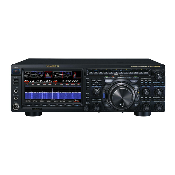
Yaesu FTDX101D Operation Manual
Hf/50mhz transceiver
Hide thumbs
Also See for FTDX101D:
- Operation manual (122 pages) ,
- Service manual (13 pages) ,
- Quick start manual (3 pages)
Table of Contents
Advertisement
Advertisement
Table of Contents

Related Manuals for Yaesu FTDX101D


Summary of Contents for Yaesu FTDX101D
- Page 1 Operation Manual...
-
Page 2: Table Of Contents
Table of Contents Accessories & options ......... 1 Split-Frequency Operation ......31 CW Mode Operation ........32 Supplied Accessories ........1 Available options ..........1 Setup for Straight Key Operation ....32 Installation and interconnections ....2 Using the Built-in Electronic Keyer ....33 FM Mode Operation........34 Antenna Considerations ........2 Connection of Antenna and Power Cables ..2 Repeater Operation ........34... -
Page 3: Accessories & Options
Accessories & options Supplied Accessories SSM-75G DC Power Cord Operation Manual Available options Reference Microphone Dual Element Microphone M-100 Ultra-High-Fidelity Desktop Microphone MD-200A8X Desktop Microphone MD-100A8X Lightweight Stereo Headphone YH-77STA External Automatic Antenna Tuner FC-40 Remote Control Keypad FH-2... -
Page 4: Installation And Interconnections
Construct the antenna and coaxial cable, or use a suitable antenna tuner, to maintain the impedance pre- sented to the FTDX101D antenna connector for an SWR of 1.5 or less. Careful preparation of the antenna and/or tuner will permit maximum performance and protect the transceiver from damage. -
Page 5: Connection Of Microphone, Headphone, Key, Keyer And Fh-2
Connection of Microphone, Headphone, Key, Keyer and FH-2 MIC GND DOWN FAST FH-2 EXT SPKR METER EXT ALC RS-232C ANT 1 ANT 2 +13.8V TUNER LINEAR DC IN RX OUT A IF OUT A RX OUT B IF OUT B... -
Page 6: Front Panel Controls & Switches
KEY jack, use only a 3-contact (“ste- SIGNAL GND will place a short between the ring and the This 8-pin jack accepts input from a microphone uti-lizing a traditional YAESU HF transceiver pinout. constant “key-down” condition. DOT DASH COMMON MIC GND... - Page 7 TUNE S.MENU This is the on/off switch for the FTDX101D Auto- Settings related to scope display. matic Antenna Tuner. Setting scope sweep speed. SPEED: Adjust the peak signal color density. PEAK: MARKER: Marker display ON or OFF. Changing scope display color.
- Page 8 MODE SPLIT Press this key to operate split frequency between Press and hold this key to display the radio modu- lation form selection screen, then touch and select your desired modulation form. [SPLIT] key for one second, the “Quick Split” fea- ture will be engaged.
- Page 9 SUB band receiver. MULTI This knob incorporates multiple tasks and makes it very convenient to operate the various functions of the FTDX101D. You can assign the desired action from the bellow. Setting scope sweep speed. SPEED: Adjust the peak signal color density.
-
Page 10: Fine Tuning
CLAR When pressed, MPVD dial will operate as CLAR Pressing the [QMB] key copies the contents (fre- dial. quency, mode, bandwidth, FM repeater offset, and RX (MAIN band) FINE TUNING Press this key to activate receive on the MAIN band When pressed, MAIN dial will operate as FINE frequency. - Page 11 When pressed, the operation of the MPVD dial operates with the function assigned in advance (see Adjusts transmission output. RF POWER: Adjusts the Monitor level. MONI LEVEL: DNR level adjustment. DNR LEVEL: NB level adjustment. NB LEVEL: VOX gain adjustment. VOX GAIN: VOX delay adjustment.
- Page 12 BAND MIC/SPEED These keys allow one-touch selection of the de- MIC (SSB and AM mode) This knob adjusts the microphone input level for also be used for direct entry of a desired operating frequency during VFO operation. Select the operation band. The band selected in the The display will show the relative micro- MAIN band is white, and the band selected by the phone gain level for 1/2 second whenever...
- Page 13 NB (MAIN band) This switch engages the MAIN band IF Noise Blanker. When the Noise Blanker is activated, the LED inside the key will glow orange. The noise blanker level can be adjusted by turning the [MULTI] knob after pressing and holding the [NB] key.
- Page 14 SHIFT (SUB band) CONT/APF (SUB band) Rotate the inner [SHIFT] knob to move the pass- CONT Press the [CONT] switch then turn the outer [CONT/ adjustment range is ±1.2 kHz. The position of the APF] knob to select the desired CONTOUR filter passband can be observed on the display.
-
Page 15: Display Indications
Display indications Operation status display Meter (MAIN band) There are four functions on the main multi-meter. Receiving signal BUSY: The bottom three selections in the list below are Transmitting transmit functions. Plus shift Minus shift Indicates the received signal strength on The tone encoder is in use ENC: the MAIN band, from S-0 to S9+60 dB. - Page 16 Scope Screen information display MAIN band SCOPE Screen. MAIN: SUB band SCOPE Screen. SUB: The operation of the scope screen HOLD: ly stopped. Frequency is constantly in the center CENTER: of the screen (for monitoring condi- tions on both sides of your operating The position of the marker moves in CURSOR: conjunction with the dial knob, and...
-
Page 17: Meter Display
Meter display Name of the meter that operates during transmission S-Meter S-Meter (MAIN band) (SUB band) Final transistor RF power Output Relative ALC voltage Final amplfier drain voltage temperature Speech compressor level Final amplfier drain current Standing Wave Ratio Select meter at transmission The lower part of the S meter is a meter that operates at the time of transmission. -
Page 18: Rear Panel
Inserting a plug into this jack disables the By plugging the FH-2 Remote Control Keypad into internal loudspeaker. this jack, direct access to the FTDX101D CPU is provided for control functions such as contest mem- ory keying, plus frequency and function control. - Page 19 RS-232C +13.8V This 9-pin serial DB-9 jack allows external comput- er control of the FTDX101D. Connect a serial cable This RCA output jack provides regulated, sepa- here and to the RS-232C COM port on your per- rately fused 13.8 VDC at up to 200 mA, to power an external device such as a packet TNC.
-
Page 20: Basic Operation
Basic Operation Turning the Transceiver Switch between ON and OFF MAIN and SUB Press and hold the Power switch to turn the transceiver ON or OFF. and the SUB band receiver (right side of the ceiver circuit configuration, different frequencies and operation The large frequency display with the underline is the current operating frequency. -
Page 21: Operating Band Selection
Operating Band Selection Operating Mode Select Press the BAND key corresponding to the Ama- Press and hold the [MODE] key, then touch the teur band on which you wish to begin operation. desired operating mode. The Indicator of the MAIN band lights “White”, and the SUB band lights “Blue”. -
Page 22: Setting The Operating Frequency
Keyboard Frequency Entry Setting the Operating 1. Touch the “Hz” area of the frequency display. Frequency Setting Frequency with the MAIN Dial Rotate the MAIN dial knob to tune within the band, and begin normal operation. selection. 2. Enter the frequency using the numeric keys. Tuning of 1 MHz or 1 kHz Erases the rightmost digit. -
Page 23: Rf Power Output Control
RF Power output control MIC Gain Adjustment Turn the [MULTI] knob to adjust the RF power Adjust microphone gain with the [MIC/SPEED] output. knob. knob of the waterfall display in the factory default. other than “RF POWER”, It may be returned to “RF POWER”: 1. -
Page 24: Receiver Accessories
Receiver Accessories RF Gain The [CLAR RX] key and MPVD Dial are used to The RF Gain control provides manual adjustment offset the receive frequency from their settings on of the gain levels for the receiver RF and IF stag- the VFO frequency. -
Page 25: Band Stack Operation
Band Stack Operation CW Decode The FTDX101D utilizes a triple band-stack VFO Alphanumeric Morse code can be decoded and selection technique that permits storing of up to displayed as text on the display. three favorite frequencies and modes onto each Interfering signals, noise, phasing, code accura- band VFO register. -
Page 26: Cw Pitch Adjustment
CW Spotting (Zero-Beating) CW Pitch Adjustment The center frequency of the receiver passband handy technique to ensure you and the other sta- may be adjusted to the CW tone you prefer. tion are precisely on 1. Press the [CW] key to engage CW operation. 2. -
Page 27: Interference Rejection
Interference Rejection IPO (Intercept Point Optimization) The IPO feature allows the operator to optimize the characteristics of the receiver front end, depending on the current noise level and the strength of incoming signals. 1. Touch [IPO]. 2. Select the desired characteristic of the receiver front end, according to the chart below. AMP1 AMP2 VC Tune Filter... -
Page 28: Contour Control Operation
Contour Control Operation IF SHIFT Operation higher or lower, without changing the pitch of the incoming signal, and thus reduces or eliminates cy components, and thus enhances the sound interference. Because the tuned carrier frequen- and readability of a received signal. cy is not varied, there is no need to re-tune the 1. -
Page 29: Width Tuning
WIDTH Tuning ATT (Attenuator) The IF WIDTH tuning system allows you to vary When extremely strong local signals or high noise the width of the DSP IF passband, to reduce or degrades reception, you can use the [ATT] button eliminate interference. to insert 6, 12, or 18-dB of RF attenuation in front Moreover, the bandwidth may actually be expand- ed from its default setting, should you wish to en-... -
Page 30: Dnr Operation
Because this is an Auto-Notch feature, there is no Touch [DNF], then select “ON” or “OFF”. Noise Blanker (NB) Operation The FTDX101D includes an effective IF Noise Blanker, which can significantly reduce noise caused by automotive ignition systems. 1. Press the [NB] key. -
Page 31: Transmitter Operation
Transmitter Operation Transmission Changing the transmission meter 1. Press the microphone PTT switch to begin transmitting. Touch the meter area and the meter selection screen will be displayed, so touch the desired transmission. meter. 2. Then touch the left meter area on the display to select the “ALC”... -
Page 32: Speech Processor
Speech Processor The FTDX101D Speech Processor is designed to increase “talk power” by increasing the average gage the transmitter automatically when you power output (via a sophisticated compression speak into the microphone. 1. Press the [VOX] key. VOX feature is activated. -
Page 33: Split-Frequency Operation
Quick Split Operation Split-Frequency Operation The Quick Split feature allows you to set a one- A powerful capability of the FTDX101D is its touch offset of +5 kHz to be applied to the SUB flexibility in Split Frequency operation using the MAIN band and SUB band frequency registers. -
Page 34: Cw Mode Operation
CW Mode Operation The powerful CW operating capabilities of the FTDX101D permit operation using an electronic keyer pad- dle, a “straight key”, or a computer-based keying device. Setup for Straight Key Operation CW Delay Time Setting 2. Press the [CW] key to engage CW operation. -
Page 35: Using The Built-In Electronic Keyer
Using the Built-in Electronic Keyer Selecting the Keyer Operating Mode The configuration of the Electronic Keyer may 2. Press the [CW] key to engage CW operation. be customized independently for the front and 3. Rotate the Main Tuning Dial knob to select rear KEY jacks of the FT DX101D. -
Page 36: Fm Mode Operation
FM Mode Operation Repeater Operation Tone Squelch Operation The FTDX101D may be utilized on 29 MHz and The “Tone Squelch” may be activated to keep the 50 MHz repeaters. receiver silent until an incoming signal modulated 1. Press and hold the [MODE] key, and then with a matching CTCSS tone is received. -
Page 37: Scope
SCOPE The FTDX101D is equipped with two types of screen mode. Center Mode (default) The “Center Mode” shows the receive frequency constantly in the center of the screen. Cursor Mode The “Cursor Mode” the position of the marker moves in conjunction with the dial knob and the screen scrolls when the marker exceeds the upper or lower limit frequency. -
Page 38: Scope Function Setting
Scope function setting The settings related to the scope display are done with the items on the screen or with the [S.MENU] key. Switch between the center mode and cursor mode of the scope display method. CTR/CRS Selects the desired fre- quency span of the Spec- SPAN trum Scope. - Page 39 Press the [S.MENU] key and the "SCOPE MENU" screen will be displayed, so touch the desired item. Setting Scope Sweep Speed. SPEED Adjust the Peak Signal Color Density. PEAK Marker display ON or OFF. MARKER Changing scope display color. COLOR Adjust the reference level to make it easier to distinguish be- LEVEL tween target signal and noise.
-
Page 40: Memory Operation
Memory Operation Memory Storage Memory Channel Recall 1. In the VFO mode, select the frequency, mode, 1. Press the [V/M] key. and status, the values you want to have stored. 2. Press and hold the [V M] k e y . 2. -
Page 41: Erasing Memory Channel Date
Erasing Memory Channel Date QMB (Quick Memory Bank) 1. Press and hold the [V M] key. dent from the regular and PMS memories. These can quickly store operating parameters for later recall. QMB Channel Storage 1. Tune to the desired frequency on the MAIN band. -
Page 42: Setting Menu
Setting Menu The Menu system of the FTDX101D provides extensive customization capability; the transceiver may be setup to comple - ment personal operating preferences. Menu items are grouped by general utilization categories. TX, RX, Memory and Scan Display SSB, AM, FM and RTTY Setting... - Page 43 Menu Function Available Settings RADIO SETTING MODE SSB AGC FAST DELAY 20 - 300 AGC MID DELAY 20 - 1000 AGC SLOW DELAY 20 - 3000 LCUT FREQ OFF/100 LCUT SLOPE 6dB/oct / 18dB/oct HCUT FREQ 700 - 3000 HCUT SLOPE 6dB/oct / 18dB/oct SSB OUT SELECT MAIN/SUB...
- Page 44 Menu Function Available Settings LCUT SLOPE 6dB/oct / 18dB/oct HCUT FREQ 700 - 3000 HCUT SLOPE 6dB/oct / 18dB/oct DATA OUT SELECT MAIN/SUB DATA OUT LEVEL 0 - 50 - 100 50 - 3050/100 - 2900/200 - 2800/300 - 2700/ TX BPF SEL 400 - 2600 DATA MOD SOURCE...
- Page 45 Menu Function Available Settings R KEYER TYPE OFF/BUG/ELEKEY - A/ELEKEY - B/ELEKEY - Y/ACS R KEYER DOT/DASH NOR/REV CW WEIGHT 2.5 - 3.0 - 4.5 NUMBER STYLE 1290/AUNO/AUNT/A2NO/A2NT/12NO/12NT CONTEST NUMBER 1 - 999 CW MEMORY 1 TEXT/MESSAGE CW MEMORY 2 TEXT/MESSAGE CW MEMORY 3 TEXT/MESSAGE...
- Page 46 Menu Function Available Settings P PRMTRC EQ2 LEVEL - 10 - 0 - 10 P PRMTRC EQ2 BWTH 0 - 1 - 10 P PRMTRC EQ3 FREQ P PRMTRC EQ3 LEVEL - 10 - 0 - 10 P PRMTRC EQ3 BWTH 0 - 1 - 10 TX GENERAL HF MAX POWER...
-
Page 47: Resetting The Microprocessor
Resetting the Microprocessor Some or all transceiver settings can be reset to their factory-default states using one of the following rou- tines: FUNC key EXTENTION SETTING EXTENTION SETTING RESET DATE&TIME MEMORY CLEAR DONE SD CARD MENU CLEAR SOFT VERSION DONE CALIBRATION ALL RESET DONE... -
Page 48: General
General Transmitter SSB Carrier Suppression: At least 60 dB below peak output Undesired Sideband Suppression: At least 60 dB below peak output 3rd-order IMD: -31dB @14 MHz 100 W PEP... -
Page 49: Receiver
Receiver Circuit Type: Double Superheterodyne 0.5 MHz - 1.8 MHz 6.3μV Maximum Audio Output: 2.5 W into 4 Ohms with 10% THD Conducted Radiation: Less than 4 nW... - Page 50 Address: 6125 Phyllis Drive, Cypress, CA 90630, U.S.A. Changes or modifications to this device that are not expressly approved by YAESU MUSEN could void the user’s authorization to operate this device. This device complies with part 15 of the FCC Rules. Operation is subject to the following two conditions: ( 1 This device may not cause harmful interference, and ( 2 this device must accept any interference including received, interference that may cause undesired operation.
- Page 51 Copyright 2019 YAESU MUSEN CO., LTD. All rights reserved. No portion of this manual may be reproduced without the permission of YAESU MUSEN CO., LTD. YAESU MUSEN CO., LTD. Tennozu Parkside Building 2-5-8 Higashi-Shinagawa, Shinagawa-ku, Tokyo 140-0002 Japan YAESU USA 6125 Phyllis Drive, Cypress, CA 90630, U.S.A.
Need help?
Do you have a question about the FTDX101D and is the answer not in the manual?
Questions and answers