Table of Contents
Advertisement
Quick Links
Advertisement
Table of Contents
Troubleshooting

Subscribe to Our Youtube Channel
Related Manuals for Gilson 333


Summary of Contents for Gilson 333
- Page 1 User's Guide 333/334 HPLC Pumps...
- Page 2 Trademarks All product and company names are trademarks™ or registered® trademarks of their respective holders. Use of the trademark(s) in this document does not imply any affiliation with or endorsements by the trademark holder(s).
-
Page 3: Table Of Contents
Description unpacking Technical specifications Customer service INSTALLATION CHAPTER 2 | Electrical Connections Cabling for TRILuTION LC Control Cabling for Control from 333 Pump Twin Pump systems Positioning the Pumps Hydraulic Connections OPERATION CHAPTER 3 | Front Panel and startup Priming... - Page 4 Reassemble Pump Head Check Valves Filters maintenance Procedures Resetting maintenance Logs Fuse Replacement TROUBLESHOOTING CHAPTER 5 | Error LED (333 Pump) Error messages (333 Pump) Troubleshooting Repair and Return Policies REPLACEMENT PARTS APPENDIX A | 333/334 HPLC Pumps Hydraulic Pump Head Electrical miscellaneous (Tools, Power Cords, Cables, etc.)
- Page 5 Hardware Configuration safety Functions Electrical Contacts manual Operations Entering method Programs method Program Worksheet File management Good Laboratory Practice (GLP Functions) Running a method Program REFERENCE INFORMATION APPENDIX E | Liquid Contact materials solvent miscibility 333/334 HPLC PumPs | usER’s GuIDE...
-
Page 7: Safety
Failure to comply with these precautions or with specific warnings elsewhere in the user’s guide violates safety standards of design, manufacture, and intended use of the instrument. Gilson assumes no liability for the customer’s failure to comply with these requirements. -
Page 8: Electronic And Hazard Symbols
CAUTION indicates a potentially hazardous situation which, if not avoided, may result in minor CAUTION or moderate injury NOTICE indicates a potentially hazardous situation which, if not avoided, may result in NOTICE equipment damage SAFETY 333/334 HPLC PUmPS... -
Page 9: Lifting
Be sure to use only replacement parts mentioned in the user’s guide. Do not repair the instrument or change parts not listed in the user’s guide. If it is necessary to replace parts not listed, please contact your local Gilson representative. 333/334 HPLC PUmPS... -
Page 11: Introduction
Chapter 1 INtrODUCtION Chapter 1 | IN thIS Chapter ● Description ● Unpacking ● Technical Specifications ● Customer Service 333/334 HPLC PUmPS | USER’S GUIDE... -
Page 12: Description
(PPmm) that functions as a static mixer, a pressure transducer, and a purge valve. The 333 Pump also has an outlet filter to protect columns from contaminants. There is a drip tray at the bottom of the pump (see Drip Tray on page 30). Solvent bottles can be placed in the tray at the top of the pump (see Solvent Bottle Tray on page 30). - Page 13 ● A purge valve which is used to manually direct the mobile phase towards the outlet filter or divert to the drain. OUtLet FILter (333 pUMp ONLY) The outlet filter protects the injection valve and the column. The outlet filter can be replaced by the user.
- Page 14 The 333 Pump features a front control panel with a display screen, soft keys, and fixed function keys. The 334 Pump does not have a front control panel and must be controlled by the 333 Pump or by TRILUTION® LC Software. Both pumps utilize standby panels to control power or indicate errors.
-
Page 15: Unpacking
It is necessary for two people to lift either the 333 Pump or 334 Pump out of the box, using the straps provided. The 333 Pump weighs approximately 33.1 kg (73 lbs.). The 334 Pump weighs approximately 29 kg (64 lbs.). -
Page 16: Technical Specifications
Technical Specifications Please be aware of the following before operating the pump. Changes or modifications to the pump not expressly approved by Gilson could void the NOTICE warranty. This instrument complies with part 15 of the FCC Rules. Operation is subject to the following two conditions: (1) This instrument may not cause harmful interference, and (2) this instrument must accept any interference received, including interference that may cause undesired operation. - Page 17 Up to 2000 m (81 kPa or 604 mmHg) Dimensions (W x D x H) 333 Pump: 26 x 41 x 50.7 cm (10.2 x 16.2 x 20 in.) 334 Pump: 26 x 41 x 38.7 cm (10.2 x 16.2 x 15.2 in.)
-
Page 18: Customer Service
If you need assistance, please contact your local Gilson representative. Specific contact information can be found at www.gilson.com. To help us serve you quickly and efficiently, please refer to Repair and Return Policies on page 58. -
Page 19: Installation
Chapter 2 | IN thIS Chapter ● Electrical Connections ● Cabling for TRILuTION LC Control ● Cabling for Control from 333 Pump ● Twin Pump systems ● Positioning the Pumps ● Hydraulic Connections This chapter describes the minimum connections required for operation (including procedures for preparing piston rinse lines). -
Page 20: Electrical Connections
Figure 9 Rear Panel Communications Port and Legend for 333 HPLC Pump Figure 10 334 HPLC Pump Rear Panel Diagram... - Page 21 You must use the default values when the 333 Pump is controlling other devices. When a 334 Pump is controlled by a 333 Pump, the baud rate must be set to 0 (External). Baud rates can also be changed to match the values of other sending and receiving devices.
- Page 22 (pin # 10) is available on the right-hand socket for feeding any suitable recorder or a PC (via a suitable interface). This analog output, which comes directly from the sensor, is for pressure only (0.142–1 V for 0–60 mPa). INsTaLLaTION 333/334 HPLC PumPs...
- Page 23 INPUT (WAIT) (Input # 1) an external relay contact, connected to this input, may be used to signal to the method Program currently running the 333 Pump that the external equipment (e.g., fraction collector, sampling injector) is ready. EMERGENCY (Input #2) Closing an external relay contact, connected to this input, may be used to signal to the pump software to start a safety Program file (file 24).
-
Page 24: Cabling For Trilution Lc Control
Plug one end of a GsIOC cable into the port marked GsIOC FROm CONTROLLER. Plug the other end into the GsIOC port of an interface module (or other controlling device, such as a Gilson liquid handler), and then connect an Rs-232 cable from the interface module (or other controlling device) to the computer. -
Page 25: Twin Pump Systems
To set up 333/334 Pumps to operate in parallel, you must give each of the paralleled pumps the same GsIOC ID: the master 333 Pump has an ID = 1 as does its twin; the slave 334 Pump and its twin both have an ID = 2, and so on. The twinned pumps are connected together using GsIOC cables. -
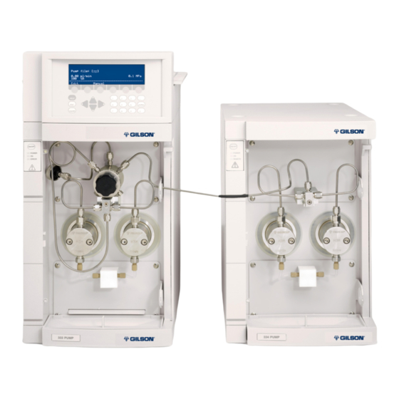
Page 26: Positioning The Pumps
Positioning the Pumps The 333/334 Pumps can be placed side-by-side or stacked to conserve bench space. Control Panel Solvent Tray Areas Standby Standby Panel Panel Outlet Tees Outlet Filter Inlet Tees Pressure Purge & Mixing Module (PPMM) Stacked Con guration... - Page 27 Side-by-Side Configuration with Tubing Port Detail Vertical Stacking Configuration stack the 333 Pump on top of the 334 Pump to conserve bench space. The tubing ports on both pumps face the same side to allow the pre-shaped tubing (part number 380132582) to connect from the PPmm on the 333 Pump to the outlet tee of the 334 Pump.
-
Page 28: Hydraulic Connections
Hydraulic Connections solvents flow through the inlet tees of the 333/334 Pumps before reaching the pump heads. solvent flows out from the pump heads to the outlet tee, through the PPmm, and finally to the outlet filter. additional solvents can be mixed in the PPmm via the additional ports on the bottom of the PPmm. - Page 29 7. Prime the solvent lines prior to operation. Follow the instructions provided in Priming on page 34 for both TRILuTION LC and manual control. Figure 22 Solvent clips in Fissures 333/334 HPLC PumPs | usER’s GuIDE...
- Page 30 The solvent bottle tray sits on top of the pump with its feet resting in the special recesses. solvent bottle solvent tray bottle tray Figure 24 Solvent Bottle Tray installed on 333 HPLC Pump (Left) and 334 HPLC Pump (Right) INsTaLLaTION 333/334 HPLC PumPs...
- Page 31 Close Up of Piston Rinse Lines details about installing piston rinse plumbing and the piston rinsing procedure, refer to Piston Rinsing Procedure on page 36. 333/334 HPLC PumPs | usER’s GuIDE...
-
Page 33: Operation
TRILuTION® LC software provides software control of the pumps for setup and operation. Refer to the TRILUTION® LC Software User’s Guide for more information. For information about front panel control of the pumps, refer to Appendix D | Front Panel Control on page 67. 333/334 HPLC PumPs | usER’s GuIDE... -
Page 34: Front Panel And Startup
PPmm fully counterclockwise to direct any flow to the purge outlet. 3. Press the ON/OFF button on the front panel; the ON indicator light should illuminate on the front panel ON/OFF ON/OFF and the display on the 333 Pump control panel should activate. POWER POWER Startup SCreeNS... - Page 35 10. Repeat steps 5–9 for any additional mobile phase instruments. This will ensure that each pump is primed individually. 11. stop the pumps by selecting Stop Pump on the manual Control window. 12. Close the purge valve on the PPmm. 333/334 HPLC PumPs | usER’s GuIDE...
- Page 36 Over time the buffer concentrate will dilute into the water bottle via entropy and laminar NOTICE flow. To prevent sediment build-up in the piston chamber, change the water and clean the bottle. OPERaTION 333/334 HPLC PumPs...
-
Page 37: Pump Operating Parameters
The inlet pressure can be adjusted from 0–50 mPa. Compressibility Compressibility is a compensation parameter for solvent compressibility. The compressibility can be adjusted from 0–2000 mbar . The standard compressibility values are 34 for water, 162 for methanol, and 180 for acetonitrile. 333/334 HPLC PumPs | usER’s GuIDE... -
Page 39: Maintenance
● Cleaning check valves and filters (clean outlet filter after changing piston seal) ● Replacing parts subject to wear and tear in each pump head: piston seal, check valves, and piston assembly ● Run-in the pump head and/or seal 333/334 HPLC PUMPS | USER’S GUIDE... -
Page 40: Maintenance Overview
Refer to the Material Safety Data Sheets for the solvents used. Cleaning Keep the pumps clean for peak performance. Always turn the power off to the pumps before cleaning. Wipe the pumps with a soft cloth dampened with a mild detergent and disinfect as needed. MAInTEnAnCE 333/334 HPLC PUMPS... -
Page 41: Pump Head
Run. 9. Select 10. Wait for the pistons to fully retract. Repeat steps 1-10 to mount the pump heads, but select TRUE for the MountHeads property in the NOTE ServiceHeads command. 333/334 HPLC PUMPS | USER’S GUIDE... - Page 42 5 mm Allen wrench. Support the pump head with your other hand while loosening the screws, alternating equally between the two. Moderate force may be required to remove the pump head. Figure 33 Loosening Pump Head Screws MAInTEnAnCE 333/334 HPLC PUMPS...
- Page 43 1. Undo the two retaining screws using a 3 mm Allen wrench (part number 4320302). Figure 35 Initial Steps for Pump Head Disassembly 2. Remove the white cap and retaining screws. Figure 36 Remove the White Cap and Retaining Screws 333/334 HPLC PUMPS | USER’S GUIDE...
- Page 44 3. Pull the piston and bellows out of the body of the pump head. Figure 37 Pull the Piston and Bellows Out of Pump Head 4. Pull apart the two halves of the pump head using a slight twisting motion. MAInTEnAnCE 333/334 HPLC PUMPS...
-
Page 45: Piston Seals
3. Push a new seal carefully into the recess. 4. Initialize and run-in the new seal(s) as described in Figure 39 Piston Seal Removal Run-In Procedure on page 52. 333/334 HPLC PUMPS | USER’S GUIDE... -
Page 46: Piston And Bellows
1. Insert the bellows tool (part number 38013235) into the open end of the bellows. This tool helps ensure that the orifice at the end of the bellows remains open while you work. Figure 44 Figure 43 Opening the Orifice Inserting the Tool MAInTEnAnCE 333/334 HPLC PUMPS... -
Page 47: Piston Rinsing Chamber
Metallic Ring Collar Figure 47 Metallic Ring and Piston Collar Seating Piston Rinsing Chamber Change the rinsing liquid at least once a week. For details, refer to Piston Rinsing Procedure on page 36. 333/334 HPLC PUMPS | USER’S GUIDE... -
Page 48: Reassemble Pump Head
(do not overtighten the screws). Figure 50 Figure 51 Refitting the White Cap Tightening the Screws Do not turn the piston after the head is reassembled, because it is possible to damage the NOTICE bellows. MAInTEnAnCE 333/334 HPLC PUMPS... -
Page 49: Check Valves
Because the dimensions of the threaded parts of the connectors are different, neither the connectors nor the cartridges are interchangeable. The check valves must not be disassembled into sub-components. no check valve sub-component is available from Gilson. Cleaning a Check Valve This procedure is carried out with the check valves installed: 1. - Page 50 14 mm wrench until there is contact, then tighten the connector by turning it a further 30° in the clockwise direction. If leakage is observed, tighten the connector progressively until the leakage stops. 7. Run the pump and perform the Leak Test Procedure on page MAInTEnAnCE 333/334 HPLC PUMPS...
-
Page 51: Filters
7. Reassemble the filter casing, using moderate force and then refit the filter to the pump and re-prime the system, and check for leaks. 333/334 HPLC PUMPS | USER’S GUIDE... -
Page 52: Maintenance Procedures
3. Repeat the first step, but for 30 minutes. Resetting Maintenance Logs 1. Select Edit > GLP > Maint from the Startup Screen on the 333 Pump control panel. Reset 2. Select to clear values. 3. navigate the screen with directional arrows to set hour limits for the following values: Seal, In CV, Out CV, and Piston. -
Page 53: Troubleshooting
Chapter 5 trOUBLeShOOtING Chapter 5 | IN thIS Chapter ● Error LED (333 Pump) ● Error Messages (333 Pump) ● Troubleshooting ● Repair and Return Policies When troubleshooting, try to check each part of the system independently. Check the solvent bottles, the connections between the bottles and pump heads, inlet filters, outlet filters, and so on. -
Page 54: Error Led (333 Pump)
Error LED (333 Pump) The ERROR light may activate (steady red) for any of the following reasons: ● A pump motor has ceased to function or has been asked to function in a way that is not possible. ● Communication has failed with a connected pump. -
Page 55: Error Messages (333 Pump)
Maintenance limit is passed for ‘M’ see Resetting Maintenance Logs on page 52 Validation process has restored default Check all method program and configuration parameter(s) parameters RAM error contact your Gilson representative Contact your local Gilson representative 333/334 HPLC PUMPs | UsER’s GUIDE... -
Page 56: Troubleshooting
No GsIOC communication or switch on the slave Pump, Pump ‘X’ is missing message the slave Pump (‘X’) is not check GsIOC connectors, the appears on the screen switched on baud rate and ID of the slave TROUbLEsHOOTING 333/334 HPLC PUMPs... - Page 57 Prime the pump, degas the Air in the hydraulics baseline noise, periodic pulses solvent Contact your Gilson Faulty pressure module representative Contact your local Gilson representative or techsupport@gilson.com for assistance resolving NOTE problems described in this chapter. 333/334 HPLC PUMPs | UsER’s GUIDE...
-
Page 58: Repair And Return Policies
Repair and Return Policies Before Calling Us Your local Gilson representative will be able to serve you more efficiently if you have the following information: ● serial number and model number of the instruments involved ○ The serial number is located inside the door on the right side of the pump. -
Page 59: Appendix A | Replacement Parts
● Miscellaneous (Tools, Power Cords, Cables, etc.) ● Service Part 333/334 HPLC Pumps PART NUMBER DESCRIPTION 333 Pump (110 and 220V), Primary Solvent, Dual-Piston, Reciprocating 38103331 Master Pump 334 Pump (110 and 220V), Secondary Solvent, Dual-Piston, Reciprocating 38103341 Remote Controlled Pump... - Page 60 Tubing, FEP, Inlet Tee to Right Pump Head, 33X Pumps 38013358 Tubing, FEP, Inlet Tee to Left Pump Head, 33X Pumps 380133592 Tubing, Stainless Steel, Horizontal, 334 Tee to 333 PPMM 380132582 Tubing, Stainless Steel, Vertical, 334 Tee to 333 PPMM 49090000...
-
Page 61: Pump Head
Piston assembly with bellows, for H3 pump head 38013238 Bellows, fluoroelastomer, piston rinsing compartment, for H3 pump head Check Valve Cartridge PART NUMBER DESCRIPTION 38013254 Inlet/Outlet Check valve cartridge, for H3 pump head Electrical PART NUMBER DESCRIPTION 6736004007 Fuse, 6.0A 333/334 HPLC PUMPS | USER’S GUIDE... -
Page 62: Miscellaneous (Tools, Power Cords, Cables, Etc.)
36460058 Priming Syringe, Glass, 10 mL 38013234 Glass bottle (Piston Rinse) Service Part Replacing this part may require assistance from your technical service representative. PART NUMBER DESCRIPTION 38013342 333 Pressure, Purge and Mixing Module (PPMM) REPLACEMENT PARTS 333/334 HPLC PUMPS... -
Page 63: Appendix Bcolumn Holder
The column holder attaches to the left side of the pump. Three pairs of column support, fitted with clips for different diameter columns, are provided in the kit. Column Support Retaining Knob Hole for Retaining Stud Retaining Knurled Column Stud Screw Support Figure 57 Column Holder 333/334 HPLC PumPS | uSER’S GuIDE... -
Page 64: Part Numbers
38013203 Column holder, equipped for 2 to 20 mm ID column 380132661 Column holder clips, 1/4" (2 mm), 2/pk 380132662 Column holder clips, 1/2" (10 mm), 2/pk 380132663 Column holder clips, 1" (20 mm), 2/pk CoLumN HoLDER 333/334 HPLC PumPS... -
Page 65: Appendix C Injector
Appendix C inJeCTOR Appendix C | in THiS CHApTeR ● Injection Valve Holder ● Connection to Injector ● Part Numbers 333/334 HPLC PumPs | usER’s GuIDE... -
Page 66: Injection Valve Holder
Valve holder with manual Rheodyne 7725i injection valve 38013206 Valve holder without valve 49931559 tubing, 316 steel, 0.25 x 1.6 x 550 mm, 27 µL (to injector, <10 mL/min) 49933509 tubing, 316 steel, 0.5 x 1.6 x 500 mm, 98 µL (to injector, >10 mL/min) INjECtoR 333/334 HPLC PumPs... -
Page 67: Appendix D | Front Panel Control
Model: 333 Head type: H3/H2 Injection from pump: YES Controlled pump: 33X(2) 30X/ 5(4) Maximum number of solvents: TWO Safety Misc Change Hard HELP ENTER CLEAR Figure 62 333 HPLC Pump Control Panel and Diagram 333/334 HPLC PUMPS | USER’S GUIDE... -
Page 68: Using The Control Panel
Used to confirm selections and store values into memory. HeLp Displays detailed help messages and indicates the screen number. CLeAR Cancels values before they are entered into memory. Used to return to the previous screen. Figure 63 Control Panel Diagram FROnT PAnEL COnTROL 333/334 HPLC PUMPS... -
Page 69: Electrical Connections
Output Signals Two outputs on the right-hand socket are dedicated to outputting signals: Contact Function Location Digital Output Converted to Analog (0–1V) Used to connect to analog recorders. Analog Output (143–1000mV) Used for pressure. 333/334 HPLC PUMPS | USER’S GUIDE... -
Page 70: Basic Control Configurations
For a binary gradient configuration, connect a 333 Pump to a 334 Pump. Solvent B is routed via the outlet tee of the 334 Pump to an inlet on the PPMM of the 333 Pump, where the two solvents are mixed. When three solvents (ternary) are to be combined, a second slave pump can be connected to the PPMM. - Page 71 Maximum number of solvents: TWO Safety Misc Change Hard 1. Connect from the outlet HELP 334 Pump (Slave) filter of the 333 Pump to ENTER CLEAR the downstream injector. 2. Connect solvent line A to PPMM the inlet tee piece on the To Downstream 333 Pump.
-
Page 72: Hardware Configuration
ENTER to confirm. For 333/334 Pumps the head type must be H3. 2. You will see one solvent channel per pump (A, B, or C). For each select the solvent type and enter a value for inlet pressure (0-50 MPa); that is the pressure at the inlet to the pump head. - Page 73 Injection Screen the solvents listed; however, selecting OTHER will require the manual entry of compressibility in Mbar ENTER 6. Key in the desired value, then press to confirm the selection. 333/334 HPLC PUMPS | USER’S GUIDE...
-
Page 74: Safety Functions
When the low pressure limit is crossed by decreasing values, the effect is delayed by 0.3 minute. The delay is to allow the Method Program to continue if an air bubble creates a brief and abrupt pressure decrease. 3. Press Next to advance to the Other Safety Functions screen. FROnT PAnEL COnTROL 333/334 HPLC PUMPS... - Page 75 4. Use the Down arrows to navigate to each option. Press Change to cycle through available selections for each option. ENTER 5. Press to confirm your selection. 333/334 HPLC PUMPS | USER’S GUIDE...
-
Page 76: Electrical Contacts
ENTER 7. Press to confirm. 8. If %A, %B, or %C is selected, key in values for the delay Volume line that appears once you’ve selected the composition parameters. 9. Press ENTER to confirm. FROnT PAnEL COnTROL 333/334 HPLC PUMPS... - Page 77 Next Units options: ● GSiOC unit id: (0-63). This must be done if the 333 Pump is slaved to another pump or Figure 73 if the default ID (#1) conflicts Miscellaneous Screen with other equipment.
-
Page 78: Manual Operations
From the Start screen press Manual > Prime to reach the Prime Screen. Priming is an essential precursor to operating any pump. Any actively associated pump (333, 334, or 30X) can be primed from the 333 Pump (master). NOTICE Running a pump head dry, even for a short time, will damage the instrument. - Page 79 ● Open to set the contact to normally open. Figure 75 ● Close to set the contact to normally Operate Output Contacts Screen closed. ● Pulse to change the state (open or closed) of the contact. 333/334 HPLC PUMPS | USER’S GUIDE...
-
Page 80: Entering Method Programs
The Link To soft key will only appear after the When Finished, Link File To line has been selected. Events 5. Press the soft key to reach the events List screen. FROnT PAnEL COnTROL 333/334 HPLC PUMPS... - Page 81 2. Key in the event time (0–9999 minutes) and flow rate. Press after each selection is keyed-in. 3. Press the Confirm soft key once the event values are set. 4. Press the soft key to add a new event. 5. Repeat Steps 2–4, as needed. 333/334 HPLC PUMPS | USER’S GUIDE...
- Page 82 3. Key in injection volume. 4. Press ENTER. 5. Key in flow rate or injection duration. 6. Press ENTER. NOTE Press the Flow/Time soft key to toggle between time and flow views. Confirm 7. Press the soft key. FROnT PAnEL COnTROL 333/334 HPLC PUMPS...
- Page 83 ● Press the Change soft key to switch the state of an output. ● Press the Select soft key to edit an event. 333/334 HPLC PUMPS | USER’S GUIDE...
-
Page 84: Method Program Worksheet
File Number: Method Name Setup parameters Pressure High limit= Low limit= number of pumps= Loops= Link file= Pump Line Model Solvent Refill Comp Head Size D or Inj i/O Operations Time Contact State Function FROnT PAnEL COnTROL 333/334 HPLC PUMPS... - Page 85 Steps Step no Time Event Operation Event 333/334 HPLC PUMPS | USER’S GUIDE...
-
Page 86: File Management
Edit Method, but without the possibility Delete of using the soft key to remove the events from the file currently selected, or to delete the file itself. However, you may copy a locked file, then edit the copied file. FROnT PAnEL COnTROL 333/334 HPLC PUMPS... - Page 87 ‘Chain circular’ means that you have cross linked files resulting in more than one occurrence of one or more file numbers in the series. Take care when linking files. Bad links can lead to unforeseen consequences. 333/334 HPLC PUMPS | USER’S GUIDE...
-
Page 88: Good Laboratory Practice (Glp Functions)
7. Select the Audit trail used field and then press the Change soft key to select On or Off. 8. Press ENTER. NOTE The date and time are saved when you switch off the 333 Pump. FROnT PAnEL COnTROL 333/334 HPLC PUMPS... - Page 89 Use this function to view the log Logs for pump head: [--] of wear parts for any configured 333 Pump or 334 Pump. The log Dismount is active for all heads contains the usage of the part to date (hours), the user set upper limit...
- Page 90 Procedure Procedure Procedure Fixed Rate Fixed Flow Rate Pressure Pressure Flow Rate mL/min mL/min Default Default Default Default mL/min mL/min 33X-H3 33X-H2 30X-5 3.75 30X-10 30X-25 18.75 30X-50 22.5 10.5 30X-100 22.5 30X-200 22.5 FROnT PAnEL COnTROL 333/334 HPLC PUMPS...
- Page 91 Test Flow and Test pressure fields and pressing ENTER. Start 3. Press the soft key to start the pump. In case of emergency, press the soft key to stop the pump. 333/334 HPLC PUMPS | USER’S GUIDE...
-
Page 92: Running A Method Program
Control screen to view the following: ● The minimum and maximum pressures attained during the last run. ● The time taken per cycle for each piston. For a complete log of events, use the Audit Trail feature. FROnT PAnEL COnTROL 333/334 HPLC PUMPS... -
Page 93: Appendix E | Reference Information
PTFE tubing is relatively porous, and compounds of low molecular weight can diffuse through the tubing wall. Use the black PTFE piston seals with organic solvents. LIQUID CONTACT MATERIALS CONTINUED ON PAGE 94 333/334 HPLC PUMPS | USER’S GUIDE... - Page 94 PTFE, PEEK, FEP, ETFE and Titanium descriptions provided by Valco Instruments Co. Inc. (www.vici.com) PCTFE description provided by Fluorotherm (www.fluorotherm.com) Stainless Steel, Type 316L description provided by new England Small Tube Corporation (www.nesmalltube.com) Ruby/Sapphire description provided by Ceramaret SA (www.ceramaret.ch) REFEREnCE InFoRMATIon 333/334 HPLC PUMPS...
-
Page 95: Solvent Miscibility
Refer to the table below when selecting solvents. For some solvents, lower toxicity alternatives are indicated [(1), (2), (3)], as follows: (1) Dichloromethane (2) Tetrahydrofuran (3) Ethanol 333/334 HPLC PUMPS | USER’S GUIDE... - Page 98 LT801422-03...
Need help?
Do you have a question about the 333 and is the answer not in the manual?
Questions and answers