Gilson GX-271 User Manual
Liquid handler
Hide thumbs
Also See for GX-271:
- User manual (124 pages) ,
- Setup instructions (5 pages) ,
- Installation qualification procedures (5 pages)
Table of Contents
Advertisement
GX-271 Liquid Handler
User's Guide
Gilson, Inc.
| PO Box 620027 | Middleton, WI 53562-0027, USA
Tel: 608-836-1551 or 800-445-7661 | Fax: 608-831-4451
Gilson S.A.S.
| 19, avenue des Entrepreneurs | BP 145 | F-95400 Villiers-le-bel, FRANCE
www.gilson.com
| sales@gilson.com | service@gilson.com | training@gilson.com
LT350012-03
©2014 Gilson, Inc. | All rights reserved.
Advertisement
Table of Contents

Subscribe to Our Youtube Channel
Related Manuals for Gilson GX-271


Summary of Contents for Gilson GX-271
- Page 1 | PO Box 620027 | Middleton, WI 53562-0027, USA Tel: 608-836-1551 or 800-445-7661 | Fax: 608-831-4451 Gilson S.A.S. | 19, avenue des Entrepreneurs | BP 145 | F-95400 Villiers-le-bel, FRANCE www.gilson.com | sales@gilson.com | service@gilson.com | training@gilson.com LT350012-03 ©2014 Gilson, Inc. | All rights reserved.
- Page 3 Syringe Installation—402 Syringe Pump ............2-14 Gilson GX-271 Liquid Handler User’s Guide...
- Page 4 GX-271 Liquid Handler Rear Panel ........
- Page 5 Miscellaneous................A-4 Gilson GX-271 Liquid Handler User’s Guide...
- Page 6 Valcon H ................. . . B-1 Table of Contents-4 Gilson GX-271 Liquid Handler User’s Guide...
- Page 7 Gilson assumes no liability for the customer’s failure to comply with these requirements.
- Page 8 WARNING indicates a potentially hazardous situation which, if not avoided, may result in serious injury CAUTION indicates a potentially hazardous situation which, if not avoided, may result in minor or moderate injury NOTICE indicates a potentially hazardous situation which, if not avoided, may result in equipment damage Safety-2 Gilson GX-271 Liquid Handler User’s Guide...
-
Page 9: Lifting
Refer to the Material Safety Data Sheets for the solvents before use. Replacement Parts Be sure to use only replacement parts mentioned in this user’s guide. If it is necessary to change parts not listed, please contact your local Gilson. Gilson GX-271 Liquid Handler User’s Guide Safety-3... - Page 11 Gilson n’assume aucune responsabilité si un client ne respecte pas ces exigences. Le détecteur a été certifié conformément aux normes de sécurité en vigueur au Canada, en Europe et aux Etats-Unis. Merci de vous reporter aux indications mentionnées sur le panneau arrière de l’instrument ainsi qu’au document de Déclaration de...
- Page 12 CAUTION indique une situation potentiellement dangereuse qui, si elle n’est pas évitée, peut entrainer des blessures mineures à modérées NOTICE indique une situation potentiellement dangereuse qui, si elle n’est pas évitée, peut entrainer des dégâts matériels Sécurité-2 Gilson GX-271 Liquid Handler User’s Guide...
-
Page 13: Levage
Se reporter aux fiches signalétiques des solvants avant toute utilisation. Pièces détachées S’assurer d’utiliser seulement les pièces détachées mentionnées dans le guide utilisateur. S’il est nécessaire de changer des pièces non listées, merci de contacter votre représentant Gilson local. Gilson GX-271 Liquid Handler User’s Guide Sécurité-3... - Page 15 Introduction This chapter provides information on the following topics: • Description • Unpacking • Customer Service • Technical Specifications Gilson GX-271 Liquid Handler User’s Guide...
-
Page 16: Description
10 μL (typical value) with high accuracy. The optional GX Direct Injection Module is mounted on the locator plate of the GX-271 Liquid Handler. The GX Direct Injection Module has an option of four different valves (for 1/8" OD sample loops or 1/16" OD sample loops). The valves available for the GX Direct Injection Module feature a vertical direct connection for the injection port. -
Page 17: Unpacking
Grip the unit below the large rectangular opening in the front of the unit. b) Lift the unit up and out of the foam packing material. lift here lift here Figure 1-3: Unpacking the Liquid Handler Gilson GX-271 Liquid Handler User’s Guide... -
Page 18: Standard Equipment
GX-271/GX-274 Liquid Handlers Documentation CD • IQ Procedure GX-271 Liquid Handler • Unpacking the GX-271/GX-274 Liquid Handler and GX-271/GX-274 ASPEC™ • Gilson Ethernet Utility Instructions on the Gilson Ethernet Utility CD • GX-27X Series Offset Utility Kit Instructions • Quality Control Checklists •... -
Page 19: Accessories
• probes • racks • GX Solvent System (included with the GX-271 Preparative Liquid Handler) • 402 Syringe Pump (Single or Dual) • GX Rinse Pump • GX Direct Injection Module (for 1/16" of 1/8" OD sample loops) •... -
Page 20: Customer Service
Introduction Customer Service Gilson, Inc. and its worldwide network of representatives provide customers with the following types of assistance: sales, technical support, applications, and instrument repair. If you need assistance, please contact your local Gilson representative. Specific contact information can be found at www.gilson.com. -
Page 21: Technical Specifications
Technical Specifications Please be aware of the following before operating the instrument. Changes or modifications to the instrument not expressly approved by Gilson could void the factory-authorized warranty. This instrument complies with part 15 of the FCC Rules. Operation is subject to the following two conditions: (1) this instrument may not cause harmful interference, and (2) this instrument must accept any interference received, including interference that may cause undesired operation. - Page 22 Sampler Type X/Y/Z with stationary rack design Software Control Computer control via Ethernet and TRILUTION software; or via RS-232 or GSIOC Vertical Punch Strength 4.5 kg (10.0 lbs.) Weight 22 kg (48 lbs.) Gilson GX-271 Liquid Handler User’s Guide...
- Page 23 625 μL ± 12 μL Selection Valve Switching Speed 180 msec Volumetric Accuracy Volume Range: 100 μL–25 mL (water) Accuracy at 500 μL: ± 10 nL Accuracy at 10 mL: ± 200 μL Weight 2.2 kg (4.9 lbs.) Gilson GX-271 Liquid Handler User’s Guide...
- Page 24 Volume range: 100 μL to 25 mL (water) Accuracy at 10 μL: ± 0.2 μL Weight 5 kg (11 lbs.) for 402 Single Syringe Pump 7 kg (15.4 lbs.) for 402 Dual Syringe Pump 1-10 Gilson GX-271 Liquid Handler User’s Guide...
- Page 25 Valve Switching Speed Analytical 200 msec for GX Direct Injection Module (1/16") Preparative 200 msec for GX Direct Injection Module (1/16") 300 msec for GX Direct Injection Module (1/8") Weight 1.2 kg (2.63 lbs.) Gilson GX-271 Liquid Handler User’s Guide 1-11...
- Page 26 High speed: 200 rpm Low speed: 120 rpm Weight 1.0 kg (2.28 lbs.) Fraction Collection Valve Technical Specification Definition 3-Way Valve Three-port, PTFE, 114 μL internal volume, 10 μL dead volume, up to 200 mL/min 1-12 Gilson GX-271 Liquid Handler User’s Guide...
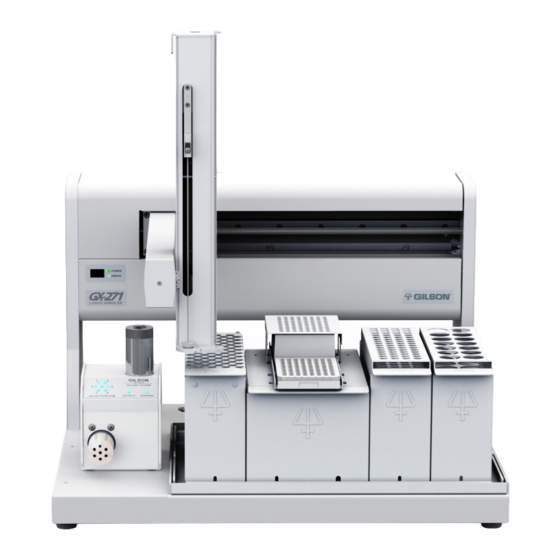
- Page 27 Z-Arm Cable Support Rod and Spiral Y-arm Wrap Installation Shield Installation (Optional) Final Z-Arm Height Adjustment tray insert locator pan locator plate Figure 2-1: GX-271 Liquid Handler with GX Solvent System, GX Rinse Pump, and GX Direct Injection Module Gilson GX-271 Liquid Handler User’s Guide...
-
Page 28: Locator Plate Setup
Figure 2-2: Locator Plate of the GX-271 Figure 2-3: Locator Plate of the GX-271 with Code 20-Series Tray Insert Installed with Code 200-Series Tray Insert Installed Gilson GX-271 Liquid Handler User’s Guide... -
Page 29: Gx Direct Injection Module Installation (Optional)
GX-271 Liquid Handler Injection Module with Riser Block Use the GX-271 Direct Inject Riser Block (part number 26035458, ordered separately) when collecting fractions to tubes 150 mm and taller or when using the Code 33X/34X-series racks. To install the riser block with the GX Direct Injection Module on the locator plate:... -
Page 30: Locator Pan Installation
Locate the two screws included with the locator pan and place them in the holes at the front of the instrument. Using a Phillips screwdriver, tighten the screws. Install the screws here Figure 2-7: Locator Pan Installation Gilson GX-271 Liquid Handler User’s Guide... -
Page 31: Rinse Station Installation
Install the outside rinse stations in the front or center positions on the tray insert. Install the drain/rinse station in the rear position on the tray insert. set up for set up for static rinse flowing rinse Figure 2-9: Rinse Station for Figure 2-10: Drain/Rinse Station for Outside Rinse of Probe Inside Rinse of Probe Gilson GX-271 Liquid Handler User’s Guide... - Page 32 After installation, check that the rinse station is perpendicular to the tray insert. If the rinse station is not flush to the tray insert and not perpendicular to the ruler, Figure 2-11: Rinse Station remove it and reinstall. Figure 2-12: Rinse Station Perpendicular to Tray Insert Gilson GX-271 Liquid Handler User’s Guide...
-
Page 33: Tray Insert Installation
Place the tray insert in the locator pan on the locator plate of the instrument. The holes on the pan insert should line up with the posts on the locator pan. Gilson GX-271 Liquid Handler User’s Guide... -
Page 34: Gx Solvent System Installation (Optional)
The solvent system is installed next to the left support on the liquid handler. There are two locator pins included with the solvent system; these pins will not be used with the GX-271 Liquid Handler. Figure 2-13: GX Solvent System on the Locator Plate of the Liquid Handler GX Rinse Pump Installation (Optional) The GX Rinse Pump sits on the locator plate of the instrument. -
Page 35: Z-Arm Setup
3 mm Allen wrench. LLD cable connector isolator probe holder 3 mm Allen wrench Figure 2-16: Isolator Probe Holder Installation Gilson GX-271 Liquid Handler User’s Guide... -
Page 36: Guide Foot Installation
Place four of the Phillips screws through the bottom of the guide foot 2.7 mm into the Z-foot and tighten. probe guide insert guide foot spots Phillips screws Figure 2-17: Guide Foot Assembly Z-foot guide foot Figure 2-18: Guide Foot Installed 2-10 Gilson GX-271 Liquid Handler User’s Guide... -
Page 37: Fraction Collection Valve Installation
Fully tighten the stop pin. The tip of the stop pin should be visible on the right side of the Z-arm. tube and wire routing strip Figure 2-20: Left Side of Z-Arm notches Note: Plumbing connections are described on page 2-36. Figure 2-21: Tube and Wire Routing Strip Installed Gilson GX-271 Liquid Handler User’s Guide 2-11... -
Page 38: Z-Arm Installation
Z-arm. The tip of the stop pin is visible on the right side of the Z-arm. Z-arm Figure 2-24: Left stop pin Side of Z-Arm Figure 2-25: Stop Pin on Right Side of Z-Arm 2-12 Gilson GX-271 Liquid Handler User’s Guide... -
Page 39: Probe Installation
Plug the other end of the cable into the LLD port on the right side of the Z-arm. LLD cable LLD port isolator probe holder Figure 2-27: LLD Cable Installation Note: Polypropylene racks, Teflon-coated probes, and microplates are not compatible with liquid level detection. Gilson GX-271 Liquid Handler User’s Guide 2-13... -
Page 40: Syringe Installation—402 Syringe Pump
Fully tighten the valve screws to secure the valve. Fully tighten the syringe to the valve. piston piston Remember or note the size of the syringe you are installing for later software operating configuration. piston holding screw Figure 2-29: Syringe Installation 2-14 Gilson GX-271 Liquid Handler User’s Guide... -
Page 41: Rear Panel Connections
Installation Rear Panel Connections The following sections provide detailed information on making rear panel connections. • For the GX-271 Liquid Handler, refer to page 2-15 • For the GX Solvent System (optional) refer to page 2-8 • For the 402 Syringe Pump (optional) refer to page 2-22 •... -
Page 42: Communication
2-18. To make an Ethernet connection to the instrument, a router and Ethernet cables are needed. Note: The router is not available from Gilson, Inc. 1 Connect power to the router Connect the power supply to the router and then connect the power supply to a power source. - Page 43 Figure 2-35: 6-Pin to 9-Pin GSIOC Cable Connection Note: When you are using more than one GSIOC module, you will need both a 6-pin to 9-pin GSIOC cable and a standard GSIOC cable (ordered separately, part number 36078143). Gilson GX-271 Liquid Handler User’s Guide 2-17...
- Page 44 The unit ID identifies the liquid handler to software packages that can issue GSIOC commands to the liquid handler. The unit ID is set to 20. There is no need to change this number unless it has been assigned to another Gilson instrument that is also connected along the GSIOC.
- Page 45 Locate the RS-232 cable provided with the interface module. Attach the male end of the RS-232 cable to the RS-232 port located on the rear panel of the interface module. Tighten the retaining screws. Attach the female end of the RS-232 cable to the computer’s RS-232 serial communications port. Tighten the retaining screws. Gilson GX-271 Liquid Handler User’s Guide 2-19...
- Page 46 The unit ID identifies the liquid handler to software packages that can issue GSIOC commands to the liquid handler. The unit ID is set to 20. There is no need to change this number unless it has been assigned to another Gilson instrument that is also connected along the GSIOC.
-
Page 47: Rear Panel Connections—Gx Solvent System (Optional)
Connect the right-angled end of the power cable (part number 26035455) to the FROM GSIOC ACCY port on the solvent system. Connect the other end of the power cable to one of the GSIOC ACCESSORIES ports on the rear panel of the GX-271 Liquid Handler. -
Page 48: Rear Panel Connections—402 Syringe Pump (Optional)
Attach the female connector of the 6-pin to 9-pin GSIOC cable to the GSIOC port on the rear panel of the 402 Syringe Pump. Tighten the retaining screws. GSIOC accessories RS-232 liquid handler Syringe Pump 6-pin to 9-pin GSIOC cable computer RS-232 cable Figure 2-42: 402 Syringe Pump connected to Liquid Handler (RS-232 Communication) 2-22 Gilson GX-271 Liquid Handler User’s Guide... - Page 49 Set the power switch to OFF. Figure 2-44: GSIOC Connect the power cord to the power receptacle on the rear panel of the syringe pump, and then Identification Number connect to power source. Gilson GX-271 Liquid Handler User’s Guide 2-23...
-
Page 50: Rear Panel Connections—Gx Rinse Pump (Optional)
Connect the 8-pin terminal block connector to the output ports on the rear panel of the liquid handler. liquid handler rear panel (partial) GX Rinse Pump input/output ports Figure 2-45: GX Rinse Pump Connected to the Liquid Handler 2-24 Gilson GX-271 Liquid Handler User’s Guide... -
Page 51: Rear Panel Connections—Gx Direct Injection Module (Optional)
Align the white dot with one of the indicated numbers. liquid handler rear panel (partial) power cable FROM GSIOC GX Direct ACCESSORY Injection port Module unit ID selector Figure 2-46: GX Direct Injection Module Connected to the Liquid Handler Gilson GX-271 Liquid Handler User’s Guide 2-25... -
Page 52: Input/Output Ports
It is designed to fit snugly into its receptacle. Figure 2-47: Input/Output Connect the opposite ends of the wires to the other device(s). Be sure to match ground Connections connections. Label each cable to identify the purpose of the connection. 2-26 Gilson GX-271 Liquid Handler User’s Guide... -
Page 53: Z-Arm Connection
2-15. Figure 2-48: Fuse Installation Power Cord Connection Locate the appropriate power cord for your line voltage. Use the power cord to connect the liquid handler to a power source. Gilson GX-271 Liquid Handler User’s Guide 2-27... -
Page 54: Connection Diagram
Connection Diagram Refer to the diagram below when making the rear panel connections. Figure 2-49: Rear Panel Connections—GX-271 Liquid Handler with Ethernet Communication Figure 2-50: Rear Panel Connections—GX-271 Liquid Handler with RS-232 Communication Figure 2-51: Rear Panel Connections—GX-271 Liquid Handler with GSIOC Communication 2-28 Gilson GX-271 Liquid Handler User’s Guide... -
Page 55: Rack Installation
Installation Rack Installation The GX-271 Liquid Handler is equipped to locate up to five Code 20-series, five Code 33X/34X-series, three Code 200-series, or three Code 300-series racks. The tray insert that was installed on page 2-7 determines which racks can be used. -
Page 56: Solvent Bottle Rack Installation
Code 300-series racks can be installed. The rack position in front of the GX Direct Injection Module must remain empty. Figure 2-55: Code 200-Series Insert on Locator Plate Figure 2-56: Code 200-series Insert on Locator Plate with Racks Installed with Racks and Direct Injection Module Installed 2-30 Gilson GX-271 Liquid Handler User’s Guide... -
Page 57: Plumbing Connections
2-35 • For the fraction collection valve refer to page 2-36 Figure 2-57: GX-271 Liquid Handler Plumbing Connections with GX Solvent System Figure 2-58: GX-271 Liquid Handler Plumbing Connections with 402 Syringe Pump Gilson GX-271 Liquid Handler User’s Guide 2-31... -
Page 58: Gx Solvent System Plumbing (Optional)
50 mL transfer tubing (part number 499486002) 600 inches of Teflon tubing (0.085" ID x 1/8" OD) Connect one end to the probe and the other end to port B on the pump. 2-32 Gilson GX-271 Liquid Handler User’s Guide... -
Page 59: Syringe Pump Plumbing (Optional)
Connect the other end to the top of the isolator probe holder. Firmly tighten this fitting since it holds the probe in place. piston operating piston holding screw Figure 2-60: 402 Syringe Pump Plumbing Connections Gilson GX-271 Liquid Handler User’s Guide 2-33... -
Page 60: Gx Rinse Pump Plumbing (Optional)
Repeat steps 6 and 7 for the bottom set of fittings. reservoir station Figure 2-62: GX Rinse Pump Tubing Installation 2-34 Gilson GX-271 Liquid Handler User’s Guide... -
Page 61: Gx Direct Injection Module Plumbing (Optional)
(part number 4903180511) to connect the tubing to port 4 on the valve. Port 5 to pump Use an MZN1PK 1/16" nut (part number 4903180411) and a ZF1PK 1/16" ferrule (part number 4903180511) to connect the tubing to port 5 on the valve. Gilson GX-271 Liquid Handler User’s Guide 2-35... -
Page 62: Fraction Collection Valve Plumbing (Optional)
While holding the valve and collection probe, insert the collection probe into the guide hole until 3 mm of tubing is exposed below the guide foot. The 1/8" tubing uses the larger guide hole and the 1/16" tubing uses the smaller guide hole. 2-36 Gilson GX-271 Liquid Handler User’s Guide... - Page 63 COLLECT position 1/16" TFE probe (part number 25077423) Information on making these connections can be found in Installing the Collection Probes page 2-36. NC (normally closed) 1/8" TFE probe (part number25077422) port to probe Gilson GX-271 Liquid Handler User’s Guide 2-37...
-
Page 64: Z-Arm Cable Support Rod And Spiral Wrap Installation
Use the extra tubing retaining clips (included in the accessory package) to contain the tubing. Spiral Wrap Use the spiral wrap included in the accessory package to contain the tubing. tubing retaining clip Z-arm cable support rod Phillips screw rear panel—partial Figure 2-67: Z-Arm Cable Support Rod 2-38 Gilson GX-271 Liquid Handler User’s Guide... -
Page 65: Shield Installation (Optional)
Place a washer and then a screw over each of the pivot pins and then tighten each screw using a Phillips screwdriver. shield pivot pin washer screw left support Figure 2-68: GX-27X Shield Installation Gilson GX-271 Liquid Handler User’s Guide 2-39... -
Page 66: Final Z-Arm Height Adjustment
While holding the adjustment tool in place, slide the Z-arm off the tool. Ensure that the bottom of the Z-arm lightly rubs against the adjustment tool as it moves. Repeat steps 2 through 5 until this is true. Z-foot Figure 2-69: Final Z-Arm Height Adjustment 2-40 Gilson GX-271 Liquid Handler User’s Guide... - Page 67 A description of the Front Panel of the liquid handler • How to Start Up the liquid handler • GX-27X Series Offset Utility for the liquid handler • Aspirate and Dispense Sequences for the GX Solvent System Gilson GX-271 Liquid Handler User’s Guide...
-
Page 68: Front Panel
2-15 if necessary. ERROR Indicator Light The yellow indicator becomes lit when an error has been encountered. Refer to Error Messages page 5-2 for a list of error messages. Figure 3-1: Front Panel (Partial) Gilson GX-271 Liquid Handler User’s Guide... -
Page 69: Start Up
Make sure the liquid handler is connected to a power source. Turn on the liquid handler using the power switch located on the rear panel. Refer to rear panel diagram on page 2-15 necessary. The POWER indicator light on the front panel illuminates. Gilson GX-271 Liquid Handler User’s Guide... -
Page 70: Gx-27X Series Offset Utility
Uninstall the previous version of the GX-27X Series Offset Utility (if necessary). Insert the CD into the drive. If the setup program does not start automatically, browse for SETUP.EXE. Install the Gilson Server (if not previously installed). • Gilson Server v1.0 for Windows® XP •... -
Page 71: Before You Begin
To start the GX-27X Series Offset Utility, click Start > All Programs > Gilson Applications > GX-27X Series > GX-27X Series Offset Utility. If any Windows Security Alerts appear with Gilson, Inc. as the Publisher, click Unblock (Windows® XP) or Allow access (Windows® 7). -
Page 72: Use The Gx-27X Series Offset Utility
Figure 3-2: Scanning for Instruments Select the instrument and then click Connect. Figure 3-3: Connect to the Instrument Select the Clamp Height and the Offset Tool and then click Set. Figure 3-4: Select the Clamp Height Gilson GX-271 Liquid Handler User’s Guide... - Page 73 If a message appears indicating that the minimum or maximum offset value has been reached, contact your local Gilson representative for assistance. Figure 3-5: Offset Site When the probe is centered, click Set to save the X and Y Offsets.
-
Page 74: Aspirate And Dispense Sequences
Dispensing Fluid to a Well Dispense sequence: The selection valve switches to reservoir (positions 2–6). The solvent system starts moving, dispensing fluid to the well. The fluid is aspirated from reservoir. well from reservoir Figure 3-9: Dispense Sequence Gilson GX-271 Liquid Handler User’s Guide... - Page 75 To obtain optimum performance and maximum life from the liquid handler, it is important to keep the instrument well-maintained. This section contains the following information to help you maintain your liquid handler. • Helpful Hints • Cleaning • Replacing Parts • Transporting the Liquid Handler Gilson GX-271 Liquid Handler User’s Guide...
-
Page 76: Helpful Hints
Check periodically to ensure that all fittings are tight. • Wipe up all spills immediately. • Allow fluids to equilibrate to room temperature before running them through the system; cold fluids may cause leakage. Gilson GX-271 Liquid Handler User’s Guide... -
Page 77: Cleaning
Hold the syringe housing in one hand. Clean the syringe using a non-abrasive cloth dampened with alcohol. Remove the piston and clean the piston with a non-abrasive cloth dampened with alcohol. Dry the syringe and piston using a clean, lint-free cloth. Gilson GX-271 Liquid Handler User’s Guide... -
Page 78: Cleaning The Fluid Path
After 10 minutes, resume priming the fluid path using distilled or deionized water. Prime until the fluid path has been flushed with water. Pause the priming sequence. Prime the fluid path using a 0.1N HCl solution. Gilson GX-271 Liquid Handler User’s Guide... - Page 79 Flush the fluid path using the bleach solution. Pause the priming sequence. After 30 minutes, resume priming the fluid path using distilled or deionized water to pump the remaining bleach solution from the tubing into a waste container. Gilson GX-271 Liquid Handler User’s Guide...
-
Page 80: Cleaning The Valve—402 Syringe Pump
Dry the components using a clean, lint-free cloth. Reassemble the valve parts by reversing the above procedure. Reinstall the syringe and valve by following the instructions on page 4-4. Reconnect the inlet, transfer, and vent tubing to the newly installed valve. Gilson GX-271 Liquid Handler User’s Guide... -
Page 81: Replacing Parts
Install the new probe by pushing it through the top of the isolator probe holder. Make sure the tip of the probe sits inside the center hole of the probe guide insert. Replace and tighten the fitting. probe guide insert guide foot Figure 4-3: Probe Replacement Gilson GX-271 Liquid Handler User’s Guide... - Page 82 It is recommended to run the GX-27X Offset Utility any time a change is made to the Z-arm, such as installing a different probe, changing the clamp height, or installing a different size probe guide insert. Refer to GX-27X Series Offset Utility on page 3-4 for more information. Gilson GX-271 Liquid Handler User’s Guide...
-
Page 83: Replacing The Syringe
Install the New Syringe To install the new syringe: Fully tighten the syringe into the valve. Figure 4-6: 402 Syringe Click Raise Syringe. Firmly tighten the piston holding screw to secure the syringe piston. Gilson GX-271 Liquid Handler User’s Guide... -
Page 84: Replacing The Piston Seal
13 Slide the piston up and down in the syringe five or six times to ensure a smooth operation between the piston and syringe. syringe barrel 14 Remount the syringe on the pump as described on page 4-4. valve screw Figure 4-8: 100 μL Syringe 4-10 Gilson GX-271 Liquid Handler User’s Guide... - Page 85 12 Slide the piston up and down in the syringe five or six times to ensure a smooth operation between the piston and syringe. 13 Make sure of the presence of the plastic cover when re-mounting the syringe on the pump. 14 Remount the syringe on the pump as described on page 4-4. Gilson GX-271 Liquid Handler User’s Guide 4-11...
- Page 86 11 Remount the syringe on the pump as Figure 4-11: 5 mL and 10 mL Syringes described on page 4-4. 4-12 Gilson GX-271 Liquid Handler User’s Guide...
-
Page 87: Replacing The Valve
Re-install the syringe. Refer to the procedure for mounting new syringe on page 4-9. Reconnect the inlet, transfer, and vent tubing to the newly installed valve. piston piston operating piston holding screw Figure 4-12: 402 Syringe Gilson GX-271 Liquid Handler User’s Guide 4-13... -
Page 88: Replacing A Fuse
Maintenance Replacing a Fuse A blown fuse may indicate the existence of another problem in the instrument. If the replacement fuses blow, don’t try others. Contact your local Gilson representative. See Before Calling Us on page 5-6. To change a fuse, follow these steps. -
Page 89: Transporting The Liquid Handler
Transporting the Liquid Handler When moving the liquid handler to another location or when sending it back to the factory, do not use the Y-arm as a handle. Always lift the liquid handler from the base. Gilson GX-271 Liquid Handler User’s Guide 4-15... - Page 91 Troubleshooting This section provides information on the following topics: • Error Messages • Mechanical Troubleshooting Electrical Troubleshooting Troubleshooting • Ethernet Connections • Repair and Return Policies Gilson GX-271 Liquid Handler User’s Guide...
-
Page 92: Error Messages
Utility to clear the error. Correct the error in the program controlling the instrument. Invalid NV-RAM address Attempt to write to an NV-RAM address that doesn't exist. Send a Home command using the Gilson Ethernet Utility to clear the error. Correct the error in the program controlling the instrument. Safety contact closed The safety contact was closed. - Page 93 XY move while busy Attempt to move to an XY location while XY is still in motion. Send a Home command using the Gilson Ethernet Utility to clear the error. Correct the error in the program controlling the instrument. Park location invalid Attempt to move to a configured park location that is out of the allowed XY ranges.
-
Page 94: Mechanical Troubleshooting
Try different AC outlet. • Check fuses; replace if necessary. • Check all liquid handler connections and make sure that the unit is plugged in. Unit blows fuses • Contact your local Gilson representative. Gilson GX-271 Liquid Handler User’s Guide... -
Page 95: Ethernet Connections
Ethernet Communication After the connections have been verified, use the procedure below to confirm Ethernet communication. Close software programs controlling Gilson system. Turn off power to the router and the Gilson system. Wait five minutes. Turn power on to the router. -
Page 96: Repair And Return Policies
Repair and Return Policies Before Calling Us Your local Gilson representative will be able to serve you more efficiently if you have the following information: • the serial number and model number of the instruments involved. Refer to the table for the location of the serial number. -
Page 97: Return Procedure
Carefully pack the unit to prevent damage in transit. Check with your distributor regarding proper method of shipment. No responsibility is assumed by Gilson or your distributor for damage caused by improperly packaged instruments. Indicate the authorization on the carton and on the packing slip. -
Page 99: Gx-271 Liquid Handler
2507235 Septum-piercing probe; side-entry, vented, capacitive level-sensing, stainless steel, strain-relief design. Dimensions: 274 x 1.8 x 0.8 mm ID (tip dimensions: 12 x 1.3 mm OD, entry hole center is 3.5 mm from tip). Gilson GX-271 Liquid Handler User’s Guide... - Page 100 220 x 1.5 x 1.1 mm ID (tip dimensions: 10 x 0.7 x 0.4 mm ID). 2507256 Beveled-tip probe, stainless steel, grooved septum-piercing; 221 x 1.5 x 0.4 mm ID. 27067375 Non-septum-piercing probe: beveled-tip, Teflon-coated stainless steel. Dimensions: 221 x 1.5 x 1.1 mm ID. Gilson GX-271 Liquid Handler User’s Guide...
-
Page 101: Other Probes (175 Mm)
Probe Guide Foot Assemblies Part Number Description 2604610 Guide foot, GX-271, 1.3 mm; includes the guide foot, probe guide insert, and six screws 2604611 Guide foot, GX-271, 1.5 mm; includes the guide foot, probe guide insert, and six screws 2604612 Guide foot, GX-271, 1.8 mm;... -
Page 102: Rinse Station
Drain/rinse station for inside rinse of probe, 125 mm 26034555 Drain/rinse station for inside rinse of probe, 175 mm Rack Accessories Part Number Description 26041033 Insert for 5 Code 20-series racks (GX-271) 26041035 Insert for 3 Code 200-series racks (GX-271) 260440005 Solvent bottle rack Miscellaneous Part Number... -
Page 103: Gx Solvent System
Transfer Tubing for GX Prep Solvent System Part Number Description 499424013 Transfer tubing 1.1 mL volume 499471112 Transfer tubing 5.5 mL volume 499474103 Transfer tubing 10.5 mL volume 499483602 Transfer tubing 30 mL volume 499486002 Transfer tubing 50 mL volume Gilson GX-271 Liquid Handler User’s Guide... -
Page 104: Syringe Pump
Transfer tubing 5.5 mL volume, 1.5 mm ID x 9.27 ft, FEP 499474103 Transfer tubing 10.5 mL volume, 1.5 mm ID 499483602 Transfer tubing 30 mL volume 499486002 Transfer tubing 50 mL volume Inlet Tubing Assembly Part Number Description 3645357 Tubing assembly, 48" INLET 25SC/215 Gilson GX-271 Liquid Handler User’s Guide... -
Page 105: Gx Rinse Pump
Replacement Parts and Accessories GX Rinse Pump Part Number Description 261452 GX Rinse Pump Assembly, 2 channel Gilson GX-271 Liquid Handler User’s Guide... -
Page 106: Low Mount Fraction Collection Valve
Low Mount Fraction Collection Valve Part Number Description 2604705 GX-271 Low Mount Fraction Collection pkg 26037270 Plumbing package for the FC Valve (GX-271/GX-281) 49953029 Tubing, 0.030" x 20 ft, PEEK 25077422 Collection Tube, 1/8" TFE 25077423 Collection Tube, 1/16" TFE 49041012 Upchurch P-201 nut, flangeless, 1/16", 1/4-28, DELRIN®... -
Page 107: Gx Direct Injection Module
250 μL stainless steel sample loop (1/16" OD) for Valco valves 494400005 500 μL stainless steel sample loop (1/16" OD) for Valco valves 49440001 1 mL stainless steel sample loop (1/16" OD) for Valco valves Gilson GX-271 Liquid Handler User’s Guide... -
Page 108: Sample Loops For Gx Direct Injection Module—Analytical (1/16") Peek
Injection port assembly, GX Direct Injection Module, for 1.5 mm OD probes, stainless steel 250510153 Injection port seal for 1.3 mm OD probes 2954674 Injection port seal for 1.5 mm OD probes 26035458 GX-271 Direct Injection Module riser block assembly A-10 Gilson GX-271 Liquid Handler User’s Guide... -
Page 109: Racks
Vessels and maximum capacity: 18 x 100 mm (25 mL) 18 x 150 mm (32 mL) Code 22U rack For 44 tubes 150498 Material: polypropylene Vessels and maximum capacity: 10–18 mm x 100–180mm Gilson GX-271 Liquid Handler User’s Guide A-11... - Page 110 Vessels and maximum capacity: 28 x 57 mm (20 mL) 28 x 60 mm (20 mL) Code 28 rack For 108 tubes 150420 Material: polypropylene Vessels and maximum capacity: 10 x 65 mm (3 mL) 10 x 75 mm (3.5 mL) A-12 Gilson GX-271 Liquid Handler User’s Guide...
- Page 111 For 60 Eppendorf vials 2704341 Material: polypropylene Vessels and maximum capacity: 7 x 30 mm (0.5 mL) Code 121 rack For 60 tubes 260440086 Material: aluminum Vessels and maximum capacity: 13 x 100 mm (9 mL) Gilson GX-271 Liquid Handler User’s Guide A-13...
- Page 112 Code 201H rack For two microplates with hold-down covers, two Eppendorf vials, and two tubes Material: aluminum 2504601H Vessels and maximum capacity: 96-well microplates Eppendorf vials (1.5 mL) 13 x 100 mm tubes (9 mL) A-14 Gilson GX-271 Liquid Handler User’s Guide...
- Page 113 Code 205 rack For two deep-well microplates, two Eppendorf vials, and two tubes Material: aluminum 2504605 Vessels and maximum capacity: 96 deep-well microplates Eppendorf vials (1.5 mL) 13 x 100 mm tubes (9 mL) Gilson GX-271 Liquid Handler User’s Guide A-15...
- Page 114 For 75 Vacutainer tubes 2504607 Material: aluminum Vessels and maximum capacity: 16 x 100 mm (12 mL) Code 208 rack For 70 vessels 2504608 Material: aluminum Vessels and maximum capacity: 18 x 150 mm (25 mL) A-16 Gilson GX-271 Liquid Handler User’s Guide...
- Page 115 Vessels and maximum capacity: 48 x 113 mm (125 mL) Code 211H rack For 9 Boston round screw-cap bottles with hold-down cover 2504611H Material: aluminum Vessels and maximum capacity: 48 x 113 mm (125 mL) Gilson GX-271 Liquid Handler User’s Guide A-17...
- Page 116 48 10.25 x 64 mm (3 mL) Note: Place the shorter tubes into the notched tube locations. Code 216 rack For 60 Waters WISP vials 2504616 Material: aluminum Vessels and maximum capacity: 15 x 45 mm (4 mL) A-18 Gilson GX-271 Liquid Handler User’s Guide...
- Page 117 For 27 vessels 2504619 Material: aluminum Vessels and maximum capacity: 30 x 95 mm (40 mL) Code 220 rack For 70 vials 2504620 Material: aluminum Vessels and maximum capacity: 17 x 62 mm (7 mL) Gilson GX-271 Liquid Handler User’s Guide A-19...
- Page 118 For 192 vials 2504624 Material: aluminum Vessels and maximum capacity: 8.5 x 41 mm Code 225 rack For 30 vials 2504625 Material: aluminum Vessels and maximum capacity: 25 x 150 mm (45 mL) A-20 Gilson GX-271 Liquid Handler User’s Guide...
- Page 119 Vessels and maximum capacity: 500 or 700 mL Code 237 rack For two microplates 2504637 Material: aluminum Vessels and maximum capacity: 384-well microplates Code 239 rack For 40 tubes 2504639 Material: aluminum Vessels and maximum capacity: 25 x 200 mm Gilson GX-271 Liquid Handler User’s Guide A-21...
- Page 120 Material: aluminum Vessels and maximum capacity: 3 mL tabless SPE 2504303 cartridges Collection block holds 12 x 32 mm (2 mL) tubes Includes cartridge holder, drain block, collection block and waste bottle with attachments. A-22 Gilson GX-271 Liquid Handler User’s Guide...
- Page 121 Material: aluminum Vessels and maximum capacity: 6 mL tabless SPE 2504306 cartridges Collection block holds 12 x 75 mm tubes (5 mL) Includes cartridge holder, drain block, collection block and waste bottle with attachments. Gilson GX-271 Liquid Handler User’s Guide A-23...
- Page 122 Code 332 rack For 44 tubes 260440079 Material: aluminum Vessels and maximum capacity: 18 x 150 mm (25 mL) Code 333 rack For 14 scintillation vials 260440036 Material: aluminum Vessels and maximum capacity: 20 mL A-24 Gilson GX-271 Liquid Handler User’s Guide...
- Page 123 For four microplates 260440095 Material: aluminum Vessels and maximum capacity: 96-well microplates (shallow or deep) Code 338 rack For 64 vials 260440106 Material: aluminum Vessels and maximum capacity: 12 x 32 mm (2 mL) Gilson GX-271 Liquid Handler User’s Guide A-25...
- Page 124 For 80 tubes 260440025 Material: aluminum Vessels and maximum capacity: 13 x 100 mm (9 mL) Code 345 rack For 44 tubes 260440041 Material: aluminum Vessels and maximum capacity: 16 x 150 mm (20 mL) A-26 Gilson GX-271 Liquid Handler User’s Guide...
-
Page 125: Materials*
This composite, a carbon fiber reinforced, PTFE lubricated inert engineering polymer, has long been the standard for typical HPLC applications in which pressures are around 5000 psi and temperatures are not more than 75°C. * Information provided by Valco Instruments Company Inc. Gilson GX-271 Liquid Handler User’s Guide...
Need help?
Do you have a question about the GX-271 and is the answer not in the manual?
Questions and answers