
Related Manuals for Trinamic IDX 7507


Summary of Contents for Trinamic IDX 7507
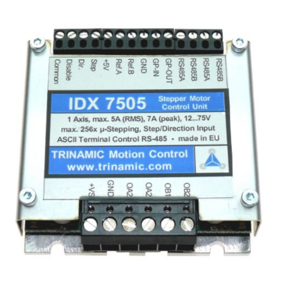
- Page 1 MODULES MODULES FOR STEPPER MOTORS V 1.17 HARDWARE MANUAL 7507 1-axis stepper motor driver 5A RMS (7A peak) 12… 75V DC RS485 TRINAMIC Motion Control GmbH & Co. KG Hamburg, Germany www.trinamic.com...
-
Page 2: Table Of Contents
Functional description ........................25 Disable function ........................25 RS485 interface ........................25 7.2.1 RS485 Commands ......................27 7.2.1.1 Examples for test move ..................28 7.2.1.2 Motor current (C) ....................28 Copyright © 2011, TRINAMIC Motion Control GmbH & Co. KG... -
Page 3: Life Support Policy
TRINAMIC Motion Control GmbH & Co. KG. Life support systems are equipment intended to support or sustain life, and whose failure to perform, when properly used in accordance with instructions Copyright © 2011, TRINAMIC Motion Control GmbH & Co. KG... - Page 4 IDX 7505 Manual (V1.17 / 2011-APR-11) provided, can be reasonably expected to result in personal injury or death. Copyright © 2011, TRINAMIC Motion Control GmbH & Co. KG...
- Page 5 Specifications are subject to change without notice. Copyright © 2011, TRINAMIC Motion Control GmbH & Co. KG...
-
Page 6: Features
2 Features The TRINAMIC IDX 7505 is a small and rugged step/direction stepper motor driver system with a supply voltage of up to up to 75V and up to 5A RMS motor coil current. It can be controlled via an RS485 interface. - Page 7 IDX 7505 Manual (V1.17 / 2011-APR-11) • Different chopper modes allow best adaptation to application / motor Copyright © 2011, TRINAMIC Motion Control GmbH & Co. KG...
-
Page 8: Order Codes
IDX 7505 Manual (V1.17 / 2011-APR-11) 3 Order codes Order codes Description Dimensions [mm] IDX 7505 75V, 5A RMS, 7A peak 63.5 x 63.5 x 18.5 Table 3.1: Order codes Copyright © 2011, TRINAMIC Motion Control GmbH & Co. KG... -
Page 9: Electrical And Mechanical Interfacing
RS485 + RS485 remote control access +, TTL input General Purpose Output, for wiring scheme see Figure 7.2 General Purpose Input, for wiring scheme see Fehler! Verweisquelle konnte nicht gefunden werden. Copyright © 2011, TRINAMIC Motion Control GmbH & Co. KG... - Page 10 Disable Opto-decoupled input (negative terminal): Tie to opto-coupler negative supply voltage to disable motor driver Common 5… 24V, optocoupler positive supply voltage Table 4.2: Pinning for GPIOs, interfaces, and switches Copyright © 2011, TRINAMIC Motion Control GmbH & Co. KG...
-
Page 11: Dimensions
4.3 Connectors Power and motor: 6 pin connector RM 5.0 (07_06_RM5) Control: Two 4 pin and one 6 pin connectors RM 3.5, (2x 166_04_RM3.5, 1x 166_06_RM35) Both connectors are RIA connectors. Copyright © 2011, TRINAMIC Motion Control GmbH & Co. KG... -
Page 12: Operational Ratings
Input high voltage on REFA / REFB Input voltage on GPI 0… 5 Output voltage on GPO (open collector) Output current on GPO (open collector) -150 Environment temperature °C Temperature of case back (cooling °C plate) Copyright © 2011, TRINAMIC Motion Control GmbH & Co. KG... - Page 13 IDX 7505 Manual (V1.17 / 2011-APR-11) Table 5.1: Operational ratings Copyright © 2011, TRINAMIC Motion Control GmbH & Co. KG...
-
Page 14: Practical Maximum Motor Current Ratings
*) This limit is due to the higher current ripple in chopper mode 2, which allows a maximum of 75% to 90% of the maximum current setting. It is not a thermal limit. Copyright © 2011, TRINAMIC Motion Control GmbH & Co. KG... -
Page 15: Step, Direction And Disable Inputs
OFF: < 1.0V >= 3.5V 5..24V Disable µC A: Anode C: Cathode C: Collector E: Emitter Step Figure 5.1: Step, Direction and Disable Inputs Examples: Copyright © 2011, TRINAMIC Motion Control GmbH & Co. KG... - Page 16 IDX 7505 Manual (V1.17 / 2011-APR-11) = 5V undefined OPTON OPTOFF = 0V 1.5V 4.0V STEP = 20V undefined OPTON OPTOFF = 0 V 16.5V 19.0V STEP Copyright © 2011, TRINAMIC Motion Control GmbH & Co. KG...
-
Page 17: Getting Started
Please consult your motor data sheet for this, as well as the choice of the chopper mode. Chopper mode 0 allows maximum motor velocity. Copyright © 2011, TRINAMIC Motion Control GmbH & Co. KG... -
Page 18: Chopper Modes 0 (Spi / Default Mode) And 1 (Pwm)
COIL, MAX MOTOR lead to an excess of motor rating. The minimum supply voltage has to be above two times the nominal motor voltage. ⋅ ≤ ≤ ⋅ ⋅ COIL MOTOR Copyright © 2011, TRINAMIC Motion Control GmbH & Co. KG... -
Page 19: Chopper Mode 2 (Phase)
4.8 mH 48 V 2.4 mH 24 V 12.5 mH 75 V 0.3 A 8 mH 48 V 4 mH 24 V Table 6.1: Maximum voltage regarding motor current and inductivity Copyright © 2011, TRINAMIC Motion Control GmbH & Co. KG... - Page 20 Any combination of motor coil current and inductivity which is above the curve for maximum supply voltage (V ) is possible to drive the motor in this mode. ICOIL /A Copyright © 2011, TRINAMIC Motion Control GmbH & Co. KG...
-
Page 21: Connecting Motor And Power Supply
100mV. Therefore we recommend to a) keep power supply cables as short as possible b) use large diameter for power supply cables Copyright © 2011, TRINAMIC Motion Control GmbH & Co. KG... -
Page 22: Emv Considerations
The maximum step frequency is 350 kHz (limited by the optocouplers). 6.5 Connections for RS485 interface The RS485-mode allows for configuration of motor parameters as well as remote control of the motor. Copyright © 2011, TRINAMIC Motion Control GmbH & Co. KG... -
Page 23: Interface Installation
IDX 7505 Manual (V1.17 / 2011-APR-11) 6.5.1 Interface installation To connect the module to a PC a RS485 interface is required, for example TRINAMIC’s new USB-2-485 or any other RS485 adapter, like the standard RS232 to RS485-converters. Input A has to be connected to RS485A of the IDX and Input B with RS485B. -
Page 24: Control With Terminal Program
RS485 mode. Setting or storing this value to the EEPROM disables step/direction control until acceleration is set to zero again (and eventually stored) or the board is reset to factory default. Copyright © 2011, TRINAMIC Motion Control GmbH & Co. KG... -
Page 25: Functional Description
The RS485 interface can control all functions of the IDX. It is possible to change parameters, with this interface which are also valid in the other modes like max. velocity or acceleration. The parameters can be written to the EEPROM to obtain the changes after a restart. Copyright © 2011, TRINAMIC Motion Control GmbH & Co. KG... - Page 26 A Reset to factory default is possible. Default address byte is A, and default baud rate is 9600 baud. This mode can only be used with an appropriate RS485 interface. Commands are sent with a terminal program, refer 6.5. Copyright © 2011, TRINAMIC Motion Control GmbH & Co. KG...
-
Page 27: Rs485 Commands
Example: BS makes B the new address byte RS485- T, t Sets the RS485-Timeout Timeout Set baud Sets baud rate for RS485 communication. U, u 0… 7 rate Refer to 7.2.1.8 Copyright © 2011, TRINAMIC Motion Control GmbH & Co. KG... -
Page 28: Examples For Test Move
The motor current can be set by the user. To do this use the RS485 command “AC” in addition with a percent value. To calculate the actual setting, please use the 100% values as shown in the table. Copyright © 2011, TRINAMIC Motion Control GmbH & Co. KG... -
Page 29: Failure Readout (E)
B low side Short circuit detected. Please check motor wiring. overcurrent bridge A low side Short circuit detected. Please check motor wiring. Table 7.3: Failure readout in SPI mode Copyright © 2011, TRINAMIC Motion Control GmbH & Co. KG... -
Page 30: Stallguard™ (G)
The parameter ‘L’ defines the different reference entrances of the module. The motor stops when the defined position is reached. Motor stops at REF_B = 0 REF_A = 0 GPI = 0 REF_B = 1 Copyright © 2011, TRINAMIC Motion Control GmbH & Co. KG... - Page 31 To activate a reference switch set the appropriate bit to 1. When motor stops the position counter is set to zero. Example: ⇒ AL 8 ENTER: Activates REF_B = 1. When destination reached, motor stops and position counter is set to zero. Copyright © 2011, TRINAMIC Motion Control GmbH & Co. KG...
-
Page 32: Output Setting (O)
1: GPO is active (LED on) 1: Output is changed at end of reference run Table 7.6: Output adjustment Figure 7.2: GPO wiring scheme 7.2.1.7 I/Os readout (Q) Command: ⇒ ENTER Port REF_B REF_A ALARM Copyright © 2011, TRINAMIC Motion Control GmbH & Co. KG... -
Page 33: Baud Rate (U)
The parameter U changes the baud rate of the module for RS485 communication. Parameter U Baud rate 9600 baud 14400 baud 19200 baud 28800 baud 38400 baud 57600 baud 76800 baud 115200 baud Table 7.8: Baud rate Copyright © 2011, TRINAMIC Motion Control GmbH & Co. KG... -
Page 34: Velocity Mode (V)
This command stores the actual parameters to the EEPROM to restart with the same performance after power down. Stored parameters are: Current setting (set by command C) • • Selected Mode (set by command M) • Output adjustment (set by command O) Copyright © 2011, TRINAMIC Motion Control GmbH & Co. KG... -
Page 35: Microstep Resolution (Z)
A resolution of up to 64 microsteps can be simulated but the motor precision is only slightly improved compared to 16 microsteps and the same as with 32 microsteps. Copyright © 2011, TRINAMIC Motion Control GmbH & Co. KG... - Page 36 The minimum supply voltage has to be above two times the nominal motor voltage. ⋅ ≤ ≤ ⋅ ⋅ COIL MOTOR It uses a chopper frequency of about 36kHz. Copyright © 2011, TRINAMIC Motion Control GmbH & Co. KG...
-
Page 37: Chopper Mode 1 (Pwm)
3. If your parameters do not fulfill the equation, i.e. you calculate a supply voltage which is below the modules’ operation specs or which does not fit your system requirements, try the following: Copyright © 2011, TRINAMIC Motion Control GmbH & Co. KG... - Page 38 If x is in the range 0.5 to 1.0, try operating your motor and check if motor or driver gets too hot. If x is above 1.0, choose one of the other chopper modes. See also 6.1.1.3 for graphical demonstration. Copyright © 2011, TRINAMIC Motion Control GmbH & Co. KG...
-
Page 39: Chopper Mode 3 (Phase And Spi)
4. This mode should only be used in very special occasions and mode 3 should be preferred if a combination of high accuracy at slow movements and high speed is needed. Copyright © 2011, TRINAMIC Motion Control GmbH & Co. KG... -
Page 40: Step/Dir
Figure 7.3: Step/dir signals and motor reactions 7.3.1 Direction The Direction signal changes the motors rotation from clockwise (CW) to counterclockwise (CCW) vice versa. Function table: open wire = 5… 24V motor CW motor CCW Copyright © 2011, TRINAMIC Motion Control GmbH & Co. KG... - Page 41 IDX 7505 Manual (V1.17 / 2011-APR-11) Copyright © 2011, TRINAMIC Motion Control GmbH & Co. KG...
-
Page 42: Step
Function table: Extern open wire = 5… 24V Intern HIGH 0.7 µs min 0.7 µs min step pulse 2.0 µs min direction DIRSETUP DIRHOLD Figure 7.4: Step and direction signal Copyright © 2011, TRINAMIC Motion Control GmbH & Co. KG... -
Page 43: Reset To Factory Default
Figure 7.6: Firmware update tool 1. Choose your RS485 connection. 2. Select your module ID (default is A). 3. Load the new firmware file (e.g. IDX_V1.08.hex), to download from www.trinamic.com. Copyright © 2011, TRINAMIC Motion Control GmbH & Co. KG... - Page 44 IDX 7505 Manual (V1.17 / 2011-APR-11) 4. Start the update process. At the end of the update process check your firmware version with command AX. Copyright © 2011, TRINAMIC Motion Control GmbH & Co. KG...
-
Page 45: Revision History
IDX with less performance deleted. Figure 7.1 new (functional description). Table 8.1: Document revision 8.2 Firmware revision Version Comment Description Pre 1.07 Please update 1.07 First Release Full functionality (except DC-Motor) with some possibilities to expand Copyright © 2011, TRINAMIC Motion Control GmbH & Co. KG... - Page 46 (controls GPO then) 1.13 Improvement Motor powered (with stand by current) directly after enabling in all modes Bug fix Stand by current in step/dir mode 0 corrected 1.14 Table 8.2: Firmware revision Copyright © 2011, TRINAMIC Motion Control GmbH & Co. KG...
Need help?
Do you have a question about the IDX 7507 and is the answer not in the manual?
Questions and answers