
Related Manuals for Trinamic MONOPACK 2


Summary of Contents for Trinamic MONOPACK 2
- Page 1 MONOPACK 2 Manual Version: 1.04 Jan 29 , 2010 Trinamic Motion Control GmbH & Co KG Sternstraße 67 D - 20357 Hamburg, Germany http://www.trinamic.com...
-
Page 2: Table Of Contents
Driving .................................. 14 4.3.1 About the Parameters ........................... 14 4.3.2 Velocity and Maximum Acceleration ($14) ..................14 4.3.3 Bow Value ($63) ............................15 4.3.4 Get Acceleration and Velocity Settings ($52) ................. 15 Copyright © 2010, TRINAMIC Motion Control GmbH & Co. KG... - Page 3 Automatic reference search ......................... 27 5.2.18 Find reference switch position ......................27 5.2.19 Set stop switch mode ........................... 27 5.2.20 Change actual position ......................... 27 5.2.21 Query actual position ..........................27 Copyright © 2010, TRINAMIC Motion Control GmbH & Co. KG...
- Page 4 Declaration of Conformity ............................33 TRINAMIC Motion Control GmbH & Co. KG does not authorize or warrant any of its products for use in life support systems, without the specific written consent of TRINAMIC Motion Control GmbH & Co. KG.
-
Page 5: Introduction
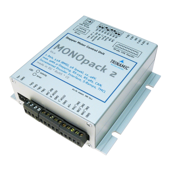
Its optional encoder feedback and a number of protection features makes this drives very dependant and reliable. The Monopack 2 can do up to 406 microsteps and needs a power supply of 12-48 Volts. -
Page 6: Connecting The Monopack 2
Connect one phase coil to the “A1” and “A2” connectors and the other phase coil to the “B1 ” and “B2” connectors. Attention: Do not connect or disconnect the motor while the Monopack 2 is powered on as this could damage the... -
Page 7: Stop Switches And Reference Switches
The 9-pin Sub-D socket provides the RS232 interface. This interface can be used in Monopack mode as well as in Monopack LT mode. The pin assignments are as follows: Signal name RS232 2=TxD 3=RxD 5=GND Copyright © 2010, TRINAMIC Motion Control GmbH & Co. KG... -
Page 8: The 25 Pin Sub-D Socket
(s. 2.4) converted to differential signals. 2.7.6 The Stop Switch Outputs The stop switch outputs (StopL+/- and StopR+/-) provide the signals from the stop switch inputs (s. 2.3) converted to differential signals. Copyright © 2010, TRINAMIC Motion Control GmbH & Co. KG... -
Page 9: The Step/Direction Input Socket
OFF: Use CAN interface; ON: Use RS485 interface OFF: Use CAN interface; ON: Use RS485 interface OFF: Use Monopack 2 (binary) command set (compatible with old Monopack) ON: Use Monopack LT (ASCII) command set (compatible with old Monopack LT) OFF: normal operation... -
Page 10: Controlling The Monopack 2
The binary command mode is selected when DIP switch #6 is in its “off” position. This mode is compatible with the old “Monopack”, with some extensions. In the binary command mode the Monopack 2 expects data telegrams via the RS232 interface, the RS485 interface or the CAN interface. With those interfaces the following parameters... -
Page 11: Monopack Lt (Ascii) Command Mode
The Monopak LT compatible command mode is selected when DIP switch #6 is in its “on” position. This command set is compatible with the old “Monopack LT” command set. In LT mode, the communication with the Monopack 2 can either take place via the RS232 interface or via the RS485 interface. The CAN interface can not be used in LT mode. -
Page 12: Binary Command Reference
Set the absolute maximum current. This command is new on the Monopack 2. On the old Monopack, the absolute maximum current could only be set using the MC0 and MC1 input. On the Monopack 2 this is also possible, but it is now better to use this command. -
Page 13: Get Current Control Settings ($53)
(less resonance). However, the actual performance depends on the motor and mechanics. For supply voltages above 24V and for low inductivity motors, best microstep behavior is reached when mixed decay setting is continuously on. Copyright © 2010, TRINAMIC Motion Control GmbH & Co. KG... -
Page 14: Driving
20 times the minimum required velocity value. 4.3.2 Velocity and Maximum Acceleration ($14) Set the acceleration and the maximum velocity. Parameter storage control (s. 4.1) P1,P2 Maximum Acceleration (1..8191) # P3,P4 Maximum Velocity (1..8191) # Copyright © 2010, TRINAMIC Motion Control GmbH & Co. KG... -
Page 15: Bow Value ($63)
0 – reference search not active 1 – reference search active (acc./vel. values are invalid!) 0 – automatic correction not active 1 – automatic correction active (acc./vel. values are invalid!) Copyright © 2010, TRINAMIC Motion Control GmbH & Co. KG... -
Page 16: Drive A Ramp ($23)
Terminate a ramp and stop the motor softly. The maximum acceleration (s. 4.3.1) parameter is used to decelerate the motor. 4.3.11 Emergency Stop ($2B) Stop the motor immediately. This command has the same functionality as setting the external alarm input high. Copyright © 2010, TRINAMIC Motion Control GmbH & Co. KG... -
Page 17: Stop And Reference Switches
After that, the reference switch is searched at first from one, then from the other side. The zero position is then set to the middle of the reference switch. Copyright © 2010, TRINAMIC Motion Control GmbH & Co. KG... -
Page 18: Reference Search Velocity ($16)
This command reads out the actual state of the stop and reference switch inputs of the Monopack. Answer State of left stop switch input (0 or 1) State of right stop switch input (0 or 1) State of reference switch input (0 or 1) Copyright © 2010, TRINAMIC Motion Control GmbH & Co. KG... -
Page 19: Incremental Encoder
Set this bit to copy the actual ramp position to the encoder counter register. The bit will be reset automatically. Reserved. Always set to zero. Direction of the encoder signals. 1: A->B, 0: B->A Copyright © 2010, TRINAMIC Motion Control GmbH & Co. KG... -
Page 20: Encoder Counter ($71)
Parameter storage control (s. 4.1) 0: automatic correction turned off 1-255: maximum number of retries for position correction after each ramp. P3,P4 end position tolerance (16 bit unsigned #) (available since firmware V2.09) Copyright © 2010, TRINAMIC Motion Control GmbH & Co. KG... -
Page 21: Pid Controller Configuration ($6A, $6B, $6C, $6D, $6F)
Parameter storage control (s. 4.1) Pid_clip_p register Pid_clip_i register Pid_clip_d register Parameter storage control (s. 4.1) Pid_clip_int_sum register Pid_clip_int_input register P3,P4 Pid_clip_sum register 0:turn off the PID controller 1:turn on the PID controller Copyright © 2010, TRINAMIC Motion Control GmbH & Co. KG... -
Page 22: Alarms And Errors
LSN of the CAN receive ID and the LSN of the RS485 address are set by the hexadecimal switch and not by command. Please see also section 3.2.2 and 2.8. Parameter storage control (s. 4.1) P1 – P4 32 bit unsigned long ID # (only 11 bits are used) Copyright © 2010, TRINAMIC Motion Control GmbH & Co. KG... -
Page 23: Set Can Send Id ($56)
Temperature (16 bit #) (units: TBD) On the old Monopack this command also returned the serial number of the device. This is no longer supported on the Monopack 2. Instead, the Monopack 2 returns the actual temperature of the device. 4.7.6 Hardware Reset ($CC) Reset the microcontroller of the MONOPACK so that all parameters are re-read from the EEPROM. -
Page 24: Monopack Lt Command Reference
Interface selection In LT mode, the Monopack 2 can either communicate via RS232 or via RS485 interface. The default interface is the RS232 interface. To use the RS485 interface it must be selected by using the Y command. This setting can then be stored in the EEPROM to make it the default setting after next power-on. -
Page 25: Set The Pre-Divider
Example: V2000 sets the velocity to 2000. Attention: The Monopack 2 uses a higher clock frequency than the Monopack LT. Thus the velocity and acceleration settings do not give identical results. To be compatible with the settings required by the Monopack LT, please multiply your velocity and acceleration settings by 0.691. -
Page 26: Hard Stop
“+”, and when the actual position is higher than the target position the direction should be set to “-“. Otherwise the motor will run until the position counter wraps around. The Monopack 2 sends back the message “to <pos_targ>” (with <pos_targ> = target position) after the command has been entered. -
Page 27: Set Mixed Decay Mode
5.2.21 Query actual position Command: p After entering this command the actual position will be sent back as a message of the form “p=<position>”, where <position> is the actual position of the motor. Copyright © 2010, TRINAMIC Motion Control GmbH & Co. KG... -
Page 28: Query Actual Velocity
Command: W After this command has been entered all parameters are stored in the EEPROM of the Monopack 2. When the EEPROM is enabled these values will be used as the power on default values. The message “Write EE” will be sent back to confirm that the parameters have been stored. -
Page 29: Set The Rs485 Address
EEPROM using the “W” command and enable the EEPROM using the “E” command. After cycling the power the Monopack 2 is in RS485 mode. Now try to use an Y command with a value lower than 9 to make RS485 faster. -
Page 30: The Monopack Pc Software
When the update / reset process is successful switch off the MONOpack2 and set back DIP-Switch 6. The Monopack2 is ready to use. Note: The program MONOpack2.exe can be found at TechLibCD and at www.trinamic.com, where the newest firmware version is also provided. -
Page 31: Application Notes
Windows 95, Windows 98 or Windows ME. Please also note that just for controlling a single Monopack 2 with a PC, an RS485 is no longer needed. Instead, the RS232 interface of the Monopack 2 can be used to connect it directly to the RS232 interface of a PC. -
Page 32: Using The "Ic485-I" Rs232 To Rs485 Converter
Ria and Wieland. Spare plugs can for example be ordered at RS Components (www.rs-components.com) with the following order numbers: Plug RS Components Order Number 2-way (Weidmüller) 403-875 4-way (Weidmüller) 403-897 5-way (Weidmüller) 209-7040 Copyright © 2010, TRINAMIC Motion Control GmbH & Co. KG... -
Page 33: Declaration Of Conformity
Immunity of radiated, radio frequency electromagnetic field EN 61000-4-6 (2003) Immunity of conducted disturbances, induced by radio frequency fields This conformity is indicated by the symbol , i.e. "Conformité Européenne". Copyright © 2010, TRINAMIC Motion Control GmbH & Co. KG... - Page 34 Monopack 2 Manual V1.04 Copyright © 2010, TRINAMIC Motion Control GmbH & Co. KG...
Need help?
Do you have a question about the MONOPACK 2 and is the answer not in the manual?
Questions and answers