Table of Contents
Advertisement
Quick Links
LIMIT CONTROLLER
Model: TC10-L Quick Guide . IM 05C01E81-11EN
rd
3
edition - February 2020
Yokogawa Electric Corporation
2-9-32 Nakacho, Musashino-shi, Tokyo 180-8750 Japan
internet site:
www.yokogawa.com
EU Declaration of conformity and Manual retrieval
TC10-L is a panel mounting, Class II instrument. It has been de-
signed with compliance to the European Directives. All information
about the controller use can be found in the Engineering Manual:
IM 05C01E81-12EN and the Communication Manual: IM 05C01E81-13EN
and General Specification: GS 05C01E81-11EN.
The EU Declaration of Conformity and the manual of the controller
can be downloaded (free of charge) from the web-site:
www.yokogawa.com/ns/tc10/im/
The Authorised Representative for this product in the EEA is:
Yokogawa Europe BV (Address: Euroweg 2 , 3825 HD Amersfoort,
The Netherlands) is the Authorised Representative of
Yokogawa Electric Corporation for this Product in the EEA.
Safety Precautions
The following general safety precautions must be observed during
all phases of operation, service and repair of this instrument.
If this instrument is used in a manner not specified in this manual,
the protection provided by this instrument may be impaired. Also,
YOKOGAWA Electric Corporation assumes no liability for the customer's
failure to comply with these requirements. The following symbol is
used on the instrument.
This manual is an essential part of the product; keep it in a safe place for
future reference. This manual is intended for the following personnel:
- Engineers responsible for installation, wiring, and maintenance of
the equipment.
- Personnel responsible for normal daily operation of the equip-
ment.
WARNING
Calls attention to actions or conditions that could cause serious or
fatal injury to the user or damage to the instrument, and indicates
precautions that should be taken to prevent such occurrences. The
user must refer to the Engineering manual for special instructions.
AC
AC/DC
The equipment wholly protected by double insulation or
reinforced insulation.
WARNING
- Whenever a failure or a malfunction of the device may cause dan-
gerous situations for persons, things or animals, please remember
that the plant must be equipped with additional devices which
will guarantee safety.
- We warrant that the products will be free from defects in material
and workmanship for 18 months from the date of manufacturing.
Products and components that are subject to wear due to conditions
of use, service life and misuse are not covered by this warranty.
Safety, Protection and Modification of the Product
- In order to protect the system controlled by this product and the
product itself, and to ensure safe operation, observe the safety
precautions described in the Engineering manual. Use of the
instrument in a manner not prescribed herein may compromise
the product's functions and the protection features inherent in
the device. We assume no liability for safety, or responsibility for
the product's quality, performance or functionality should users
fail to observe these instructions when operating the product.
- Installation of protection and/or safety circuits with respect to a
lightning protector; protective equipment for the system controlled
by the product and the product itself; foolproof or failsafe design
of a process or line using the system controlled by the product or
the product itself; and/or the design and installation of other
protective and safety circuits are to be appropriately implemented
as the customer deems necessary.
- This product is not designed or manufactured to be used in critical
applications that directly affect or threaten human lives. Such
applications include nuclear power equipment, devices using
radioactivity, railway facilities, aviation equipment, air navigation
facilities, aviation facilities, and medical equipment. If so used,
CONFIGURATION PARAMETERS SETTING
-L
Press the
key
Confirm and go to
Next parameter
for 3 seconds
Increase the displayed value
or select the next element
-L
Decrease the displayed value
or select the previous element
Go to the groups
Go to the next group
To exit the
procedure press the
P
AS
3
(default: 0)
3
for more than 6 seconds
-L
it is the user's responsibility to include in the system additional
equipment and devices that ensure personnel safety.
- Modification of the product is strictly prohibited.
- This product is intended to be handled by skilled/trained person-
nel for electric devices.
- Overvoltage category: II
WARNING
- This instrument is for Measurement Category No. 1. Do not use it
for measurements in locations falling under Measurement Catego-
ries No. 2, No. 3 and No. 4.
Internal wiring
Cable
III O T
entrance
IV
Outlet
No. EN 61010-2-030
No. 1 O (Other)
For measurements performed on circuits not directly
connected to MAINS.
No. 2 Measurement
For measurements performed on circuits directly
Category II
connected to the low-voltage installation.
No. 3 Measurement
For measurements performed in the building instal-
Category III
lation.
No. 4 Measurement
For measurements performed at the source of the
Category IV
low-voltage installation.
How to Connect Wires
WARNING
- Wiring work must be carried out by a person with basic electrical
knowledge and practical experience.
- Be sure to turn OFF the power supply to the controller before wiring
to avoid an electric shock. Use a tester or similar device to ensure
that no power is being supplied to a cable to be connected.
- As a safety measure, always install a circuit breaker (an IEC 60947
compatible product, 5 A, 100 V or 220 V AC) in an easily accessible
location near the instrument. Moreover, provide indication that the
switch is a device for turning off the power to the instrument.
- Install the power cable keeping a distance of more than 1 cm from
other signal wires.
- The power cable is required to meet the IEC standards concerned or the
requirements of the area in which the instrument is being installed.
- Wiring should be installed to conform to NEC (National Electrical
Code: ANSI/NFPA-70) or the wiring construction standards in
countries or regions where wiring will be installed.
- For control relay output, alarm relay output, and power terminal
connections, use heat-resistant cables.
- Recommended tightening torque: 0.5 Nm.
Model and suffix codes
Model Code
Suffix codes
L H C o R o D o F /GK Temperature Controller
TC10
Fixed code L
Power supply H
Fixed code
C
N
Retransmission
A
Limit control output
R
N
Alarm output 1,2
R
Fix code
D
N
Serial communication
S
Fixed code
F
Option Code
/GK Panel gasket for IP65
NOTE about the structure of this document
The usual installation sequence is the reverse of the operator
sequence.
During installation, the first step is the wiring procedure followed
by the complete configuration. At this point you can set the operator
parameter and than you can use the instrument.
This document follows this structure.
InP Group
N
Param.
Parameters setting
1
2
config.
parameter setting
3
key
4
5
6
7
8
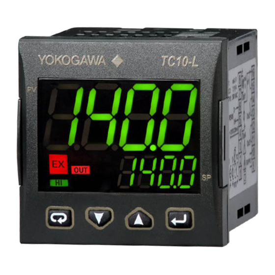
DISPLAY AND KEYS
Unit
(°C/°F)
Exceeded
indication
PV
High
Limiter
EX
OUT
Limit
HI
AL1 AL2
Control
II
Output
Description
Operator Mode
Access to:
- Operator visualizations
(PV, max or min, time)
-
Editing
Parameters
-
Editing
Configuration
Confirming operation
(Pressed when OUT LED lit
and EX LED is OFF.)
ELECTRICAL CONNECTIONS
Relay output 2,3: 2A, 250 V AC, resistive load
Linear output
: 0/20 mA , 0/10 V
RS485
Description
Always "-L"
100 to 240 VAC
Always "C"
None
Measured value retransmission
12V DC
out 4 to 20 mA
(note)
PV
Limit control relay output
None
Alarm output: 2 points (OP3 relay
4 to 20 mA
+ OP4 SSR)
2 wiretransmitter
Always "D"
None
RS485 Modbus
Always "F"
PV
4 to 20 mA
3 wiretransmitter
SEnS
Decimal point figure
dP
Note: For TC and RTD inputs the decimal figure must be 0 or 1 only.
Initial scale readout
SSc
NOTE: This parameter will be shown only when a linear input has been selected (mV, V or mA).
Full scale readout
FSc
NOTE: This parameter will be shown only when a linear input has been selected (mV, V or mA).
Engineering unit
unit
NOTE: This parameter will be shown only when a TC or RTD input has been selected.
Digital filter on the measured value.
FiL
Note: This filter will affect the measured value but also the control action the analogue retransmission and the alarms
behaviour.
bS
PV input bias
di.A
Digital Input action
DIMENSIONS
Overall dimensions (L x H x D): 48 x 48 x 73 mm
Process Value
Panel Cut-out (L x H):
(in eng. units)
-L
MOUNTING
Set Point
Param. valueor
State/Function
(Editing mode)
PK
SP
Alarms
active
Mounting requirements
Editing Mode
This instrument is intended for permanent installation, for indoor
use only, in an electrical panel which encloses the rear housing,
exposed terminals and wiring on the back.
Confirm and go to
Select a mounting location having the following characteristics:
Next parameter
1. It should be easily accessible;
2. There is minimum vibrations and no impact;
3. There are no corrosive gases;
Increase the displayed
4. There are no water or other fluids (i.e. condensation);
value or select the
5. The ambient temperature is in accordance with the operative
next element of the
temperature (0 to 50°C);
list
6. The relative humidity is in accordance with the instrument
Decrease the displayed
specifications (20 to 90%);
value or select the
7. Installation altitude: less than 2000 m;
previous element
8. Pollution category: 2;
Exit from Operator
The instrument can be mounted on panel with a maximum
commands/Parameter
thickness of 8 mm.
setting/Configuration
When the maximum front protection (IP65) is desired, the optional
gasket must be mounted.
Output 1: 4-20 mA
OP1
Output 4: 0-12V DO
OP4
(note)
Analogue input
Thermo-
mV, V
mA
couple
Note: Terminal 4 can be programmed as:
12VD C
Pt1000
Pt100
- 0 to 12 V SSR Drive Output (OP4) connecting
(note)
- 12 Vdc (20 mA) transmitter power supply
Description
(1.89 x 1.89 x 2.87 in.)
45
+0.6
x 45
+0.6
mm
(1.78
x 1.78
in.)
+0.023
+0.023
65 mm min.
2.56 in min.
+0.6
45
mm
+0.023
1.78
in
This is mandatory for FM approval
!
TERMINALS
DI1
10 V,
Pin connector
6 mA
∅
1.4 mm max.
(0.055 in.)
Limiter
Output
(OP 2)
L
Stripped wire
L:
5.5 mm
OP3
(0.21 in.)
100 to 240 V AC
Line
(-15 to +10 %)
Neutral
6.5 VA max
50/60 Hz
the load between terminals 4 and 16;
connecting the 2 wire transmitter between
terminals 4 and 1; for 3 wire transmitter connect
terminal 4 to transmitter power supply input and
terminal 1 and 2 to transmitter signal output.
Dec.
Range value or selection list elements
point
J = TC J
crAL = TC K,
S = TC S,
r = TC R
t = TC T,
n = TC N
Pt1 = PT 100,
Pt10 = PT 1000,
dP
0.60 = 0 to 60 mV,
12.60 = 12 to 60 mV,
0.20 = 0 to 20 mA,
4.20 = 4 to 20 mA,
0.5 = 0 to 5 V,
1.5 = 1 to 5 V,
0.10= 0 to 10 V
2.10 = 2 to 10 V,
0 to 3
dP
-1999 to 9999
dP
-1999 to 9999 (E.U.)
dP
°c or °F
0( oFF) to 20.0 (s)
1
-100 to 100 % of the input span
dP
0 = DI1 direct
1 = DI1 reverse
Advertisement
Table of Contents

Related Manuals for YOKOGAWA TC10-L


Summary of Contents for YOKOGAWA TC10-L
- Page 1 Outlet EU Declaration of conformity and Manual retrieval TC10-L is a panel mounting, Class II instrument. It has been de- No. EN 61010-2-030 Description +0.6 No. 1 O (Other) For measurements performed on circuits not directly signed with compliance to the European Directives.
- Page 2 OUT group Decimal Param. Description Range value or selection list elements figure Decimal Param. Description Range value or selection list elements figure 0 = no function Alarm 2 function +1 = not active at power up 0.20 = 0-20 mA Out 1 type +2 = Relative alarm not active at set point change.
- Page 3 Instrument operativity 1 Introduction The TC10-L is an FM (both FM3545 and FM3810) approved limit controller that can be configured either as a high limit or as a low limit controller by a user. The TC10-L features - universal input,...
- Page 4 Navigation, access levels and keyboard management Hardware specifications The TC10-L is equipped with 3 different levels: Measuring input Thermocouples Level 1 Type: J,K,S,R,T,N programmable. At power up the instrument starts in “Operator Mode” (in this document O.M.) Continuity detection current: 250 nA When in O.M., the keyboard will operate as follows:...
Need help?
Do you have a question about the TC10-L and is the answer not in the manual?
Questions and answers