Table of Contents
Advertisement
Quick Links
INSTRUCTION MANUAL
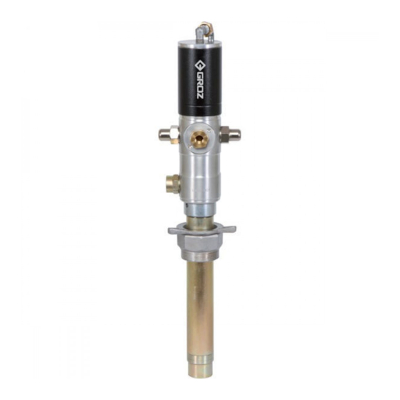
Air Operated 1:1 Oil Ratio Pump
OP-11
Congratulations on purchase of this World Class Air Operated Oil Ratio Pump !
• World-class Industrial Oil Dispensing pumps with
guaranteed performance & hassle free operation
• Used as transfer pumps to quickly transfer oils from large
drums to smaller containers. Pumps are designed to work
in tough conditions & are ideal for use with low to medium
viscosity oils (up to SAE 80) for transferring over short
distances (up to 5 metres).
• All metal construction, fully CNC machined with hardened
wear resistant moving parts
• Reciprocating piston operated 2-1/2" (63 mm) dia. Air Motor
• Stub Pumps are supplied with Non Return Valve threaded
1" (F) for use on the bottom of the Suction Tube. Other
pump lengths have a built in Strainer at pump inlet to keep
contaminants away
• Pumps are double acting with discharge up to 40 LPM
(10.58 GPM). Air Consumption is 270 LPM (71.5 GPM)
• Also available complete with Oil bar tap & connecting
links (ODS series, used as an Air Operated Oil Dispenser to
quickly & conveniently dispense Oils from Drums.
• Available in four different versions - Stub, 16 Gal, 55 Gal &
ODS version
PUMP CONSTITUENTS
1.
Pump Assembly
2.
Bung Nut
3.
Oil Bar Tap with connecting links
(Only in ODS Version)
1
Stub Version
16 Gal Version
OP/S/11B
OP/T2/11B
ODS Version
ODS/T3/11B
Fig. 1
3
2
1
S1221, Rev C
55 Gal Version
OP/T3/11B
Advertisement
Table of Contents

Related Manuals for Groz OP-11


Summary of Contents for Groz OP-11
-
Page 1: Pump Constituents
INSTRUCTION MANUAL S1221, Rev C Air Operated 1:1 Oil Ratio Pump OP-11 Congratulations on purchase of this World Class Air Operated Oil Ratio Pump ! Stub Version 16 Gal Version 55 Gal Version • World-class Industrial Oil Dispensing pumps with guaranteed performance &... -
Page 2: Table Of Contents
Contents Page No. PUMP CONSTITUENTS ....................PUMP CONSTRUCTION ....................GETTING STARTED ......................PUMP INSTALLATION & OPERATION ................MAINTENANCE & REPAIR ..................... • Repair Kit Replacement ..................EXPLODED VIEW ......................PARTS LIST ........................10-11 TROUBLESHOOTING ......................REPLACEMENT & SERVICE PARTS PROGRAM .............. 13-15 • Replacement Parts Program .................. -
Page 3: Pump Construction
PUMP CONSTRUCTION The pump is made up of two sections as below :- Fig. 2 • DRIVE SECTION:- It consists of an Air Motor Assembly driven by compressed air. The piston DRIVE SECTION diameter of the air motor is 2.5” / 63 mm. The motor consists of an air cylinder with piston and one reciprocal valve with a nylon slider. -
Page 4: Maintenance & Repair
MAINTENANCE & REPAIR (Refer to Exploded View - Page 9) General Precautions • Before performing any service operation, always shut off the air supply and release the system pressure i.e. let the media out so that the pressure decreases. When storing the pump assembly out of the drum, cover the Filter Tube (71) with Filter Cap (72). • Be careful not to damage any parts when dismantling. -
Page 5: Repair Kit Replacement
Repair Kit Replacement (Refer to Table 4 - Page 15) Pull out Filter Cap (72) by Hold a nose plier into the hand. Hold Barrel (67) in pin holes of Non Return (58) and turn the Piston a soft-jaw vice. Tighten a 1/2”... - Page 6 Loosen both Coupling 11. Connect a caliper wrench Nuts (2) using wrench into the holes on inlet (size 21 mm). Cover (29). Unscrew it anticlockwise. 12. Unscrew both Pushers (19) using wrench (size 25 mm) or a pneumatic Remove Bend Pipe (1) wrench with 25 mm along with both Coupling socket.
- Page 7 On removal, Slider Rod 18. Remove Slider Guide (22). (27) is still connected either to Plunger Rod (11) or Piston Rod (49). In either case, hold Slider Rod (27) in a vice & unscrew the other rod with wrench (size 10 mm). Slider Rod Slider Guide 19.
- Page 8 21. Replace the Repair Kits as mentioned in Table 4 - Page 15, by following the steps 1-20 in reverse order taking care of • While replacing Repair the points below: Kit (KIT/PST/T3/11B), note that Piston • Ensure all mating Assembly comes already surfaces are clean assembled with Lower...
-
Page 9: Exploded View
EXPLODED VIEW Fig. 3 KIT/01/T3/11B KIT/SEL/T3/11B KIT/PST/T3/11B KIT/NRV/T3/11B Apply thread sealant on the threads of Plunger Rod (11), Slider Rod (27), Piston Rod (49) & Barrel (67) Component (74) consists of an Oil Bar Tap with 2 Connecting Links & 2 Elbows (ONLY IN ODS VERSION) NON RETURN VALVE IN STUB PUMP ONLY... -
Page 10: Parts List
PARTS LIST Table 1 REFERENCE NO. FROM EXPLODED VIEW DESCRIPTION QUANTITY Bend Pipe Coupling Nut Sealing Ring Bend Cylinder Cover O Ring BS141 Cylinder Plunger Nut Rubber Plunger Steel Washer Plunger Rod O Ring BS614 Rod Guide O Ring BS116 Pusher Button Pusher Nut Pusher Spring... - Page 11 REFERENCE NO. FROM EXPLODED VIEW DESCRIPTION QUANTITY Spring Holder Seal Seal Holder Seal Nut Piston Rod Pusher (Piston) Seal Holder (Piston) Seal Support (Piston) Piston Seal Seal Support (Middle) Wavy Washer O Ring BS029 Adapter (Piston) Non Return (Piston) Lower Cylinder Nyloc Nut Non Return O Ring BS130...
-
Page 12: Troubleshooting
TROUBLESHOOTING (Refer to Exploded View - Page 9) Table 2 PROBLEM POSSIBLE CAUSE SOLUTION Make sure that media used has a viscosity of SAE 80 or Media viscosity is too high lower Drum is Empty Media level inside the drum may be too low. Refill drum Pump operates, but does not dispense media at all Pump inlet is blocked... -
Page 13: Replacement & Service Parts Program
REPLACEMENT & SERVICE PARTS PROGRAM (Refer to Exploded View - Page 9) REPLACEMENT PARTS PROGRAM Table 3 REFERENCE NO. FROM EXPLODED VIEW PART NO. DESCRIPTION QUANTITY BUNG/OP/42 Bung KIT/ODS Oil Bar Tap with Connecting Links... -
Page 14: Service Parts Program
SERVICE PARTS PROGRAM Fig. 4 KIT/01/T3/11B Replace Component No. O Ring O Ring 20, 21 & 23 as a SET. ORG/BS141 ORG/BS129 Seat SET/RP O Ring ORG/BS121 Nylon Slider O Ring SLD/NY/RP ORG/BS119 Paper Seal O Ring ORG/BS614 SEL/R/RP O Ring O Ring ORG/BS126 ORG/BS617... - Page 15 SERVICE PARTS PROGRAM Table 4 KIT PART NO. KIT DESCRIPTION CONSTITUENT NO. PART DESCRIPTION REF. SUPPLY PER KIT CONDITION SET/RP Seat SEL/P/RP Paper Seal SLD/NY/RP Nylon Slider ORG/BS617 O Ring ORG/BS614 O Ring KIT/01/T3/11B AIR MOTOR KIT ORG/BS141 O Ring AS SET ORG/BS129 O Ring...
-
Page 16: Specifications
Village Kherki Daula, National Highway-8 Gurgaon-122001, Haryana, INDIA TEL +91.124.282.7700 / 221.4050 FAX +91.124.2827986 / 221.4224 FAX (USA) +1.509.271.7848 FAX (UK) +44.870.121.1854 E-MAIL info@groz-tools.com www.groz-tools.com The Groz name, Groz logo and the mark are trademarks of Groz Engineering Tools (P) Ltd. India...
Need help?
Do you have a question about the OP-11 and is the answer not in the manual?
Questions and answers