WIKA F2301 Operating Instructions Manual
Tension/compression force transducer
Hide thumbs
Also See for F2301:
- Operating instructions manual (96 pages) ,
- Operating instructions manual (124 pages)
Table of Contents
Advertisement
Available languages
Available languages
Advertisement
Chapters
Table of Contents

Related Manuals for WIKA F2301


Summary of Contents for WIKA F2301
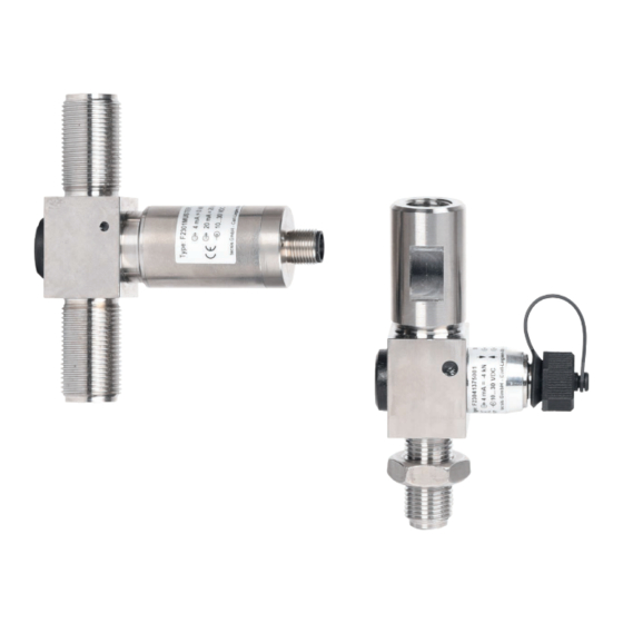
- Page 1 Operating instructions Betriebsanleitung Tension/compression force transducer Models F2301, F23C1, F23S1, F2303, F2304 Zug-/Druckkraftaufnehmer Typen F2301, F23C1, F23S1, F2303, F2304 Example: Models F2301, F2304...
- Page 2 Marken in verschiedenen Ländern. ® ® Prior to starting any work, read the operating instructions! Keep for later use! Vor Beginn aller Arbeiten Betriebsanleitung lesen! Zum späteren Gebrauch aufbewahren! WIKA operating instructions, models F2301, F23C1, F23S1, F2303, F2304...
-
Page 3: Table Of Contents
..... . 34 9.2 Dimensions model F2301 ....35 9.3 Dimensions models F2301 (signal jump) and F23C1 . -
Page 4: General Information
Negative power supply terminal Positive output terminal Negative output terminal Positive power supply terminal for relay (signal jump) Negative power supply terminal for relay (signal jump) Shield Case x-pin Pin assignment WIKA operating instructions, models F2301, F23C1, F23S1, F2303, F2304... -
Page 5: Design And Function
2.1 Overview models F2301, F23C1, F23S1 Force introduction (spherical surface) Counter nut Measuring tube Electrical connection Swivel heads (optional) WIKA operating instructions, models F2301, F23C1, F23S1, F2303, F2304... -
Page 6: Overview Model F2303
Measuring tube Electrical connection 2.2 Overview model F2304 Force introduction Counter nut Measuring tube Electrical connection WIKA operating instructions, models F2301, F23C1, F23S1, F2303, F2304... -
Page 7: Description
... indicates a potentially dangerous situation in the hazardous area that can result in serious injury or death, if not avoided. Information ... points out useful tips, recommendations and information for efficient and trouble-free operation. WIKA operating instructions, models F2301, F23C1, F23S1, F2303, F2304... -
Page 8: Intended Use
Improper handling or operation of the instru- ment outside of its technical specifications requires the instrument to be taken out of WIKA operating instructions, models F2301, F23C1, F23S1, F2303, F2304... -
Page 9: Improper Use
■ intended use. that personal protective equipment is available. ■ WIKA operating instructions, models F2301, F23C1, F23S1, F2303, F2304... -
Page 10: Personnel Qualification
The operator is in no way relieved of his obligations under labour law for the safety and the protection of workers' health. The design of the personal protective equipment must take into account all operating parameters of the place of use. WIKA operating instructions, models F2301, F23C1, F23S1, F2303, F2304... -
Page 11: Labelling, Safety Marks
Address Force direction (tension or compression force) Power supply, excitation voltage for mV/V sensor Output signal Product code Date of manufacture calendar week/year Approval-related product information WIKA operating instructions, models F2301, F23C1, F23S1, F2303, F2304... -
Page 12: Ex Marking
-40 °C to +85 °C -40 °C to +100 °C F*3C*.****.17************* -45 °C to +85 °C -45 °C to +100 °C F*3C*.****.21************* T4 and group I -40 °C to +85 °C WIKA operating instructions, models F2301, F23C1, F23S1, F2303, F2304... -
Page 13: Signal Jump Electronics
The upper measuring range limit of 20 mA will never be reached and thus the testing of the signal jump is enabled. WIKA operating instructions, models F2301, F23C1, F23S1, F2303, F2304... -
Page 14: Transport
Dust, dirt, and other objects may not be deposited in such a way that they form a ■ force shunt with the measuring tube, since this will falsify the measuring signal. WIKA operating instructions, models F2301, F23C1, F23S1, F2303, F2304... -
Page 15: Precautions Before Mounting
Do not use the tension/compression force transducer as a climbing aid. ■ If high shear forces or lateral forces are to be expected, the use of ■ swivel heads is recommended (see chapter 10 “Accessories”). WIKA operating instructions, models F2301, F23C1, F23S1, F2303, F2304... -
Page 16: Mounting Of Models F2301, F23C1 And F23S1
If necessary, object against the spherical surface/face secure with locknut. Observe the max. of the force transducer. Load the force torque. Load the force transducer. transducer. WIKA operating instructions, models F2301, F23C1, F23S1, F2303, F2304... -
Page 17: Mounting Of Models F2301, F23C1 And F23S1 With Swivel Heads
5. Commissioning, operation 5.4 Mounting of models F2301, F23C1 and F23S1 with swivel heads Counter nut Swivel heads Thread Clamping system Force transducer Retaining bolt Screw swivel heads onto the thread. -
Page 18: Mounting Of Model F2303
The retai- the measuring object. Observe the max. ning bolt must not restrict the free location torque. Load the force transducer. of the force transducer. WIKA operating instructions, models F2301, F23C1, F23S1, F2303, F2304... -
Page 19: Mounting Of Model F2304
As necessary, object against the spherical surface/face secure with locknut. Observe the max. of the force transducer. Load the force torque. Load the force transducer. transducer. WIKA operating instructions, models F2301, F23C1, F23S1, F2303, F2304... -
Page 20: Electrical Connection
ISO 11898-2. Care should be taken about the shielding. 5.7.1 Pin assignment of analogue output, models F2301, F2303, F2304 Output 4 ... 20 mA, 2-wire Output 0...10 V, 4 ... 20 mA, 3-wire... - Page 21 4 ... 20 mA 0…10 V 2-wire 3-wire 3-wire 0V/UB- Shield Case Case Case Cable assignment Cable colour 2-wire 3-wire Brown UB+/S+ White Blue 0V/S- 0V/S-/UR- Black Only when using standard cable, e.g. EZE53X011016 WIKA operating instructions, models F2301, F23C1, F23S1, F2303, F2304...
- Page 22 2006/42/EC. ® 5.7.5 Pin assignment, CANopen Circular connector M12 x 1, 5-pin Shield UB+ (CAN V+) UB- (CAN GND) Bus signal, CAN-High Bus signal, CAN-Low Circular connector M12 x 1, 5-pin WIKA operating instructions, models F2301, F23C1, F23S1, F2303, F2304...
-
Page 23: Electrical Connection Hazardous Area
If faults cannot be eliminated by means of the measures listed, the tension/compression force transducer must be taken out of operation immediately. ▶ Contact the manufacturer. ▶ If a return is needed, please follow the instructions given in chapter 9.2 “Return”. WIKA operating instructions, models F2301, F23C1, F23S1, F2303, F2304... -
Page 24: Maintenance And Cleaning
For contact details see chapter 1 “General information” or the back page of the operating instructions. 7.1 Maintenance This instrument is maintenance-free. Repairs must only be carried out by the manufacturer. Only use original parts (see chapter 10 “Accessories”). WIKA operating instructions, models F2301, F23C1, F23S1, F2303, F2304... -
Page 25: Cleaning
24 months. The basic settings will be corrected if necessary. 8. Dismounting, return and disposal 8.1 Dismounting Release the load from the tension/compression force transducer and disconnect from power. Remove the tension/compression force transducer from the mounting. WIKA operating instructions, models F2301, F23C1, F23S1, F2303, F2304... -
Page 26: Return
8.2 Return Strictly observe the following when shipping the instrument: All instruments delivered to WIKA must be free from any kind of hazardous substances (acids, bases, solutions, etc.) and must therefore be cleaned before being returned. When returning the instrument, use the original packaging or a suitable transport packaging. - Page 27 404, communi- 2006/42/EC cation services LSS (CiA 305), configuration of the instrument address and baud rate Sync/ Async, Node/Lifeguarding, heartbeat; zero and span ±10 % adjustable via entries in the object directory WIKA operating instructions, models F2301, F23C1, F23S1, F2303, F2304...
- Page 28 1) Relative linearity error is specified in acc. with Directive VDI/VDE/DKD 2638 Chap. 3.2.6. 2) Protocol in accordance with CiA 301, device profile 404, communication service LSS (CiA 305). ® ® CANopen and CiA are registered community trademarks of CAN in Automation e. V. WIKA operating instructions, models F2301, F23C1, F23S1, F2303, F2304...
- Page 29 Current output 4 … 20 mA Current output 4 … 20 mA 2-wire: Signal current 2-wire: Signal current Current output 4 … 20 mA 3-wire: < 8 mA Voltage output: < 8 mA WIKA operating instructions, models F2301, F23C1, F23S1, F2303, F2304...
- Page 30 1) The force transducers with ignition protection type “ib” should only be powered using galvanically isolated repeater power supplies. 2) Relative linearity error is specified in acc. with Directive VDI/VDE/DKD 2638 Chap. 3.2.6. 3) Other signal jumps are realisable upon request. WIKA operating instructions, models F2301, F23C1, F23S1, F2303, F2304...
- Page 31 (STEP, IGES) on request 1) Relative linearity error is specified in acc. with Directive VDI/VDE/DKD 2638 Chap. 3.2.6. 2) Protocol in accordance with CiA 301, device profile 404, communication service LSS (CiA 305). WIKA operating instructions, models F2301, F23C1, F23S1, F2303, F2304...
- Page 32 Ingress protection (per EN/IEC 60529) IP67 Vibration resistance 20 g, 100 h, 50 ... 150 Hz (to DIN EN 60068-2-6) Wiring protection Reverse polarity, overvoltage and short-circuit resis- tance Interference emission DIN EN 55011 WIKA operating instructions, models F2301, F23C1, F23S1, F2303, F2304...
- Page 33 2) Relative linearity error is specified in acc. with Directive VDI/VDE/DKD 2638 Chap. 3.2.6. 3) Protocol in accordance with CiA 301, device profile 404, communication service LSS (CiA 305). ® ® CANopen and CiA are registered community trademarks of CAN in Automation e. V. WIKA operating instructions, models F2301, F23C1, F23S1, F2303, F2304...
-
Page 34: Approvals
-25 °C < T < +85 °C Ex ib IIC T4 Gb -40 °C < T < +85 °C USA and Kanada Approvals for components Eurasian Economic EMC directive Community ■ WIKA operating instructions, models F2301, F23C1, F23S1, F2303, F2304... -
Page 35: Dimensions Model F2301
61.5 Rated force N -0.1 Sphere R Rated displacement in kN (Nm) < 0.02 1, 2, 3 < 0.02 < 0.02 M20 x 1.5 < 0.2 M20 x 1.5 < 0.2 WIKA operating instructions, models F2301, F23C1, F23S1, F2303, F2304... - Page 36 Rated displacement in kN -0.1 (Nm) M24 x 2 < 0.2 M39 x 3 2,500 < 0.2 M45 x3 4,000 < 0.2 M56 x4 6,000 < 0.2 M64 x4 9,000 < 0.2 WIKA operating instructions, models F2301, F23C1, F23S1, F2303, F2304...
-
Page 37: Dimensions Models F2301 (Signal Jump) And F23C1
Rated force in kN 25.2 91.5 25.2 91.5 25.2 91.5 91.5 27.5 27.5 91.5 92.5 Rated force N -0.1 Sphere R MA (Nm) in kN M20 x 1.5 M20 x 1.5 WIKA operating instructions, models F2301, F23C1, F23S1, F2303, F2304... - Page 38 Rated force ØA in kN 91.5 90.2 19.5 91.5 Rated force N -0.1 Sphere R MA (Nm) Rated displacement in kN M24 x 2 < 0.2 M39 x 3 2,500 < 0.2 WIKA operating instructions, models F2301, F23C1, F23S1, F2303, F2304...
-
Page 39: Dimensions Model F23S1
M16 x 1.5 12-26 27.5 27.6 20.2 30.2 152.5 M20 x 1.5 18-40 27.6 152.5 M24 x 2 31-70 157.4 M30 x 2 67-151 47.8 19.7 67.5 177.4 M42 x 2 WIKA operating instructions, models F2301, F23C1, F23S1, F2303, F2304... -
Page 40: Dimensions Model F2303
M20 x 1.25 male thread 28.7 M20 x 1.25 24.5 Rated Version ∅K L force in kN female thread male thread 117.5 92.5 30.5 female thread male thread male thread 117.5 92.5 30.5 WIKA operating instructions, models F2301, F23C1, F23S1, F2303, F2304... - Page 41 All dimensions in mm. Rated Version ∅B ∅D ∅D force in 0.008 female thread 20.7 M16 x 1.5 female thread 24.2 M20 x 1.5 Rated Version ∅K force in female thread female thread 144.5 WIKA operating instructions, models F2301, F23C1, F23S1, F2303, F2304...
-
Page 42: Dimensions Model F2304
SW1 SW2 ØN1 ØN2 Sphe- Rated force re R (Nm) displace- in kN ment 21.5 < 0.5 21.5 < 0.5 21.5 24.5 12.5 < 0.5 7.5, 10 21.5 24.5 12.5 < 0.5 WIKA operating instructions, models F2301, F23C1, F23S1, F2303, F2304... - Page 43 140.5 M20 x 1.5 50.5 170.5 M24 x 3 Rated ØS SW1 SW2 ØS ØN1 ØN2 Sphere Rated force (Nm) displace- in kN ment 20, 25 16.5 < 0.5 < 0.5 WIKA operating instructions, models F2301, F23C1, F23S1, F2303, F2304...
-
Page 44: Accessories
Accessory: Swivel heads in accordance with DIN ISO 12240-4 ØD1 = 12 ... 25 mm dimension range K ØD2 = 40 ... 80 mm dimension range E All dimensions in mm. WIKA operating instructions, models F2301, F23C1, F23S1, F2303, F2304... - Page 45 0.415 20 H7 24.3 M20 x 1.5 0.750 25H7 29.6 M24 x 2 M39 x 3 -0.012 M45 x 3 -0.012 77.9 M56 x 4 -0.015 89.4 M64 x 4 -0.015 WIKA operating instructions, models F2301, F23C1, F23S1, F2303, F2304...
-
Page 46: Appendix: Eu Declaration Of Conformity
Appendix: EU declaration of conformity WIKA operating instructions, models F2301, F23C1, F23S1, F2303, F2304... - Page 47 Appendix: EU declaration of conformity WIKA operating instructions, models F2301, F23C1, F23S1, F2303, F2304...
- Page 48 Appendix: EU declaration of conformity WIKA operating instructions, models F2301, F23C1, F23S1, F2303, F2304...
- Page 49 9.1 Zulassungen ..... 80 9.2 Typ F2301 Abmessungen ....81 9.3 Typen F2301 (Signalhub) und F23C1 Abmessungen .
-
Page 50: Allgemeines
Zwei Anschlussleitungen dienen zur Spannungsversorgung. Eine Anschlussleitung dient für das Messsignal. Positiver Versorgungsanschluss Negativer Versorgungsanschluss Positiver Messanschluss Negativer Messanschluss Positiver Versorgungsanschluss für Relais (Signalhub) Negativer Versorgungsanschluss für Relais (Signalhub) Schirm Gehäuse x-polig Pinbelegung WIKA Betriebsanleitung, Typen F2301, F23C1, F23S1, F2303, F2304... -
Page 51: Aufbau Und Funktion
2. Aufbau und Funktion 2. Aufbau und Funktion 2.1 Überblick Typen F2301, F23C1, F23S1 Krafteinleitung (ballige Oberfläche) Kontermutter Messfeder Elektrischer Anschluss Gelenkköpfe (optional) WIKA Betriebsanleitung, Typen F2301, F23C1, F23S1, F2303, F2304... -
Page 52: Überblick Typ F2303
2.3 Überblick Typ F2303 Krafteinleitung Messfeder Elektrischer Anschluss 2.2 Überblick Typ F2304 Krafteinleitung Kontermutter Messfeder Elektrischer Anschluss WIKA Betriebsanleitung, Typen F2301, F23C1, F23S1, F2303, F2304... -
Page 53: Beschreibung
Bereich hin, die zum Tod oder zu schweren Verlet- zungen führen kann, wenn sie nicht gemieden wird. Information ... hebt nützliche Tipps und Empfehlungen sowie Informationen für einen effizienten und störungsfreien Betrieb hervor. WIKA Betriebsanleitung, Typen F2301, F23C1, F23S1, F2303, F2304... -
Page 54: Bestimmungsgemäße Verwendung
Verwendungszweck konzipiert und konstruiert und darf nur dementsprechend verwen- det werden. Die technischen Spezifikationen in dieser Betriebsanleitung sind einzuhal- ten. Eine unsachgemäße Handhabung oder ein Betreiben des Gerätes außerhalb der technischen Spezifikationen macht die sofortige Stilllegung und Überprüfung durch WIKA Betriebsanleitung, Typen F2301, F23C1, F23S1, F2303, F2304... -
Page 55: Fehlgebrauch
Erste Hilfe und Umweltschutz unterwiesen wird, sowie die Betriebsanlei- tung und insbesondere die darin enthaltenen Sicherheitshinweise kennt. dass das Gerät gemäß der bestimmungsgemäßen Verwendung für den ■ Anwendungsfall geeignet ist. dass die persönliche Schutzausrüstung verfügbar ist. ■ WIKA Betriebsanleitung, Typen F2301, F23C1, F23S1, F2303, F2304... -
Page 56: Persönliche Schutzausrüstung
Der Betreiber wird durch diese Vorschläge in keinster Weise von seinen arbeitsrechtlichen Pflichten zur Sicherheit und dem Schutz der Gesundheit der Arbeitnehmer entbunden. Die Bemessung der persönlichen Schutzausrüstung muss unter Berücksichtigung aller Betriebsparameter des Einsatzortes erfolgen. WIKA Betriebsanleitung, Typen F2301, F23C1, F23S1, F2303, F2304... -
Page 57: Beschilderung, Sicherheitskennzeichnungen
Seriennummer, TAG-Nummer Messbereich Anschlussbelegung Schutzart gem. DIN EN 60259 Adresse Kraftrichtung (Zug- oder Druckkraft) Versorgungsspannung, Speisespannung bei mV/V-Sensor Ausgangssignal Produktcode Herstellungsdatum Kalenderwoche/Jahr Zulassungsrelevante Produkinformationen WIKA Betriebsanleitung, Typen F2301, F23C1, F23S1, F2303, F2304... -
Page 58: Ex-Kennzeichnung
F*3C*.****.16************* -40 °C bis +85 °C -40 °C bis +100 °C F*3C*.****.17************* -45 °C bis +85 °C -45 °C bis +100 °C F*3C*.****.21************* T4 und Gruppe I -40 °C bis +85 °C WIKA Betriebsanleitung, Typen F2301, F23C1, F23S1, F2303, F2304... -
Page 59: Signalhub-Elektronik
Mit einem fest eingestellten Signalhub von beispielsweise 4 mA kann dann in jedem Betriebszustand bei Aktivierung des Prüfrelais der Testzyklus ausgelöst werden. Die obere Messbereichsgrenze von 20 mA wird jedoch nicht erreicht und dadurch die Überprüfung des Signalhubs ermöglicht. WIKA Betriebsanleitung, Typen F2301, F23C1, F23S1, F2303, F2304... -
Page 60: Transport
Folgende Einflüsse vermeiden: Mechanische Vibration, mechanischer Schock (hartes Aufstellen) ■ Staub, Schmutz und sonstige Gegenstände dürfen sich nicht so ablagern, dass ■ sie einen Kraftnebenschluss zur Messfeder bilden, da dadurch das Messsignal verfälscht wird. WIKA Betriebsanleitung, Typen F2301, F23C1, F23S1, F2303, F2304... -
Page 61: Vorkehrung Vor Der Montage
Veränderung des Nullsignals eine dauerhafte Schädi- gung zur Folge haben. Den Zug-/Druckkraftaufnehmer nicht als Steighilfe verwenden. ■ Sind hohe Querkräfte bzw. Seitenkräfte zu erwarten, empfiehlt sich der ■ Einsatz von Gelenkköpfen (siehe Kapitel 10 „Zubehör“). WIKA Betriebsanleitung, Typen F2301, F23C1, F23S1, F2303, F2304... -
Page 62: Montage Typen F2301, F23C1, F23S1
Gegenstück des Messobjekts auf freies Gegenstück des Messobjekts gegen Gewinde aufschrauben. Gegebenfalls mit ballige Oberfläche/Stirnfläche des Kraft- Kontermutter kontern. Max. Drehmoment aufnehmers positionieren. Kraftaufnehmer beachten. Kraftaufnehmer belasten. belasten. WIKA Betriebsanleitung, Typen F2301, F23C1, F23S1, F2303, F2304... -
Page 63: Montage Typen F2301, F23C1, F23S1 Mit Gelenkköpfen
5. Inbetriebnahme, Betrieb 5.4 Montage Typen F2301, F23C1, F23S1 mit Gelenkköpfen Kontermutter Gelenkköpfe Gewinde Haltevorrichtung Kraftaufnehmer Haltebolzen Kontermuttern auf Gewinde aufschrauben. Gelenkköpfe auf Gewinde aufschrauben. ... -
Page 64: Montage Typ F2303
Gelenkkopf in Haltevorrichtungen positi- Kraftaufnehmer auf Gewinde des onieren und mit Haltebolzen fixieren. Der Messobjekts aufschrauben. Max. Drehmo- Haltebolzen darf die freie Lagerung des ment beachten. Kraftaufnehmer belasten. Kraftaufnehmers nicht beeinträchtigen. WIKA Betriebsanleitung, Typen F2301, F23C1, F23S1, F2303, F2304... -
Page 65: Montage Typ 2304
Gegenstück des Messobjekts auf freies Gegenstück des Messobjekts gegen Gewinde aufschrauben. Gegebenfalls mit ballige Oberfläche/Stirnfläche des Kraft- Kontermutter kontern. Max. Drehmoment aufnehmers positionieren. Kraftaufnehmer beachten. Kraftaufnehmer belasten. belasten. WIKA Betriebsanleitung, Typen F2301, F23C1, F23S1, F2303, F2304... -
Page 66: Elektrischer Anschluss
Rundstecker M12 x 1, 4-polig Rundstecker M12 x 1, 4-polig Rundstecker M12 x 1, 4-polig 4 ... 20 mA 4 ... 20 mA 0 …10 V 2-Leiter 3-Leiter 3-Leiter 0V/UB- Schirm Gehäuse Gehäuse Gehäuse WIKA Betriebsanleitung, Typen F2301, F23C1, F23S1, F2303, F2304... - Page 67 4 ... 20 mA 0…10 V 2-Leiter 3-Leiter 3-Leiter 0V/UB- Schirm Gehäuse Gehäuse Gehäuse Kabelbelegung Kabelfarbe 2-Leiter 3-Leiter Braun UB+/S+ Weiss Blau 0V/S- 0V/S-/UR- Schwarz Nur bei Verwendung der Standardkabel, z. B. EZE53X011016 WIKA Betriebsanleitung, Typen F2301, F23C1, F23S1, F2303, F2304...
- Page 68 Ausführung gem. Anforderung nach funktionaler Sicherheit gem. Maschinenrichtlinie 2006/42/EG. ® 5.7.5 Anschlussbelegung CANopen Rundstecker M12 x 1, 5-polig Schirm UB+ (CAN V+) UB- (CAN GND) Bus-Signal CAN-High Bus-Signal CAN-Low Rundstecker M12 x 1, 5-polig WIKA Betriebsanleitung, Typen F2301, F23C1, F23S1, F2303, F2304...
-
Page 69: Elektrischer Anschluss Ex-Bereich
Können Störungen mit Hilfe der aufgeführten Maßnahmen nicht besei- tigt werden, den Zug-/Druckkraftaufnehmer unverzüglich außer Betrieb setzen. ▶ Kontakt mit dem Hersteller aufnehmen. ▶ Bei notwendiger Rücksendung die Hinweise unter Kapitel 9.2 „Rücksendung“ beachten. WIKA Betriebsanleitung, Typen F2301, F23C1, F23S1, F2303, F2304... -
Page 70: Wartung Und Reinigung
7. Wartung und Reinigung Kontaktdaten siehe Kapitel 1 „Allgemeines“ oder Rückseite der Betriebs- anleitung. 7.1 Wartung Dieses Gerät ist wartungsfrei. Reparaturen sind ausschließlich vom Hersteller durchzuführen. Nur Originalteile verwenden (siehe Kapitel 10 „Zubehör”). WIKA Betriebsanleitung, Typen F2301, F23C1, F23S1, F2303, F2304... -
Page 71: Reinigung
24 Monaten durch den Hersteller rekalibrieren zu lassen. Die Grundeinstellungen werden wenn notwendig korrigiert. 8. Demontage, Rücksendung und Entsorgung 8.1 Demontage Den Zug-/Druckkraftaufnehmer entlasten und vom Strom trennen. Den Zug-/Druckkraft- aufnehmer aus der Einbausituation entfernen. WIKA Betriebsanleitung, Typen F2301, F23C1, F23S1, F2303, F2304... -
Page 72: Rücksendung
8. Demontage, Rücksendung und Entsorgung 8.2 Rücksendung Beim Versand des Gerätes unbedingt beachten: Alle an WIKA gelieferten Geräte müssen frei von Gefahrstoffen (Säuren, Laugen, Lösungen, etc.) sein und sind daher vor der Rücksendung zu reinigen. Zur Rücksendung des Gerätes die Originalverpackung oder eine geeignete Transportverpackung verwenden. - Page 73 Sicherheit gem. Maschi- CiA 301, Geräteprofil 404, nenrichtlinie 2006/42/EG Kommunikationsdienst LSS (CiA 305), Konfiguration der Geräte-Adresse u. Baudrate Sync/Async, Node/Lifeguar- ding, Heartbeat; Nullpunkt und Spanne ±10 % einstellbar über Einträge ins Objektverzeichnis WIKA Betriebsanleitung, Typen F2301, F23C1, F23S1, F2303, F2304...
- Page 74 1) Relative Linearitätsabweichung ist gem. Richtlinie VDI/VDE/DKD 2638 Kap. 3.2.6 angegeben. 2) Protokoll gem. CiA 301, Geräteprofil 404, Kommunikationsdienst LSS (CiA 305). ® ® CANopen und CiA sind registrierte Gemeinschaftsmarken des CAN in Automation e. V. WIKA Betriebsanleitung, Typen F2301, F23C1, F23S1, F2303, F2304...
- Page 75 -40 … +85 °C Lagerungstemperatur B T, S Elektrischer Anschluss Rundsteckverbinder M12 x 1, 4-polig 4 … 20 mA, 2-Leiter 4 … 16 mA, Ausgangssignal 2-Leiter (Nennkennwert) C DC 2 … 8 V, 3-Leiter WIKA Betriebsanleitung, Typen F2301, F23C1, F23S1, F2303, F2304...
- Page 76 1) Die Kraftaufnehmer mit der Zündschutzart „ib“ dürfen nur mit potenzialgetrennten Speisegeräten versorgt werden. 2) Relative Linearitätsabweichung ist gem. Richtlinie VDI/VDE/DKD 2638 Kap. 3.2.6 angegeben. 3) Andere Signalhübe sind auf Anfrage realisierbar. WIKA Betriebsanleitung, Typen F2301, F23C1, F23S1, F2303, F2304...
- Page 77 EMV-geschützte Ausführungen) Optionen Zeugnisse, Festigkeitsnachweise, 3D-/CAD Daten (STEP, IGES) auf Anfrage 1) Relative Linearitätsabweichung ist gem. Richtlinie VDI/VDE/DKD 2638 Kap. 3.2.6 angegeben. 2) Protokoll gem. CiA 301, Geräteprofil 404, Kommunikationsdienst LSS (CiA 305). WIKA Betriebsanleitung, Typen F2301, F23C1, F23S1, F2303, F2304...
- Page 78 Bürde für Stromausgang Schutzart (nach EN/IEC 60529) IP67 Vibrationsbeständigkeit 20 g, 100 h, 50 ... 150 Hz (nach DIN EN 60068-2-6) Elektrische Schutzarten Verpolungs-, Überspannungs- und Kurzschluss- schutz DIN EN 55011 Störemission WIKA Betriebsanleitung, Typen F2301, F23C1, F23S1, F2303, F2304...
- Page 79 2) Relative Linearitätsabweichung ist gem. Richtlinie VDI/VDE/DKD 2638 Kap. 3.2.6 angegeben. 3) Protokoll gem. CiA 301, Geräteprofil 404, Kommunikationsdienst LSS (CiA 305). ® ® CANopen und CiA sind registrierte Gemeinschaftsmarken des CAN in Automation e. V. WIKA Betriebsanleitung, Typen F2301, F23C1, F23S1, F2303, F2304...
-
Page 80: Zulassungen
Ex ib I Mb -25 °C < T < +85 °C Ex ib IIC T4 Gb -40 °C < T < +85 °C USA und Kanada Komponentenzulassung Eurasische Wirt- EMV-Richtlinie schaftsgemeinschaft ■ WIKA Betriebsanleitung, Typen F2301, F23C1, F23S1, F2303, F2304... -
Page 81: Typ F2301 Abmessungen
27,6 27,5 61,5 Nennkraft N -0,1 Kugel R MA (Nm) Nennmessweg in kN < 0,02 1, 2, 3 < 0,02 < 0,02 M20 x 1,5 < 0,2 M20 x 1,5 < 0,2 WIKA Betriebsanleitung, Typen F2301, F23C1, F23S1, F2303, F2304... - Page 82 Kugel R MA (Nm) Nennmessweg in kN M24 x 2 < 0,2 M39 x 3 2.500 < 0,2 M45 x3 4.000 < 0,2 M56 x4 6.000 < 0,2 M64 x4 9.000 < 0,2 WIKA Betriebsanleitung, Typen F2301, F23C1, F23S1, F2303, F2304...
-
Page 83: Typen F2301 (Signalhub) Und F23C1 Abmessungen
Alle Maße in mm. Nennkraft in kN 25,2 91,5 25,2 91,5 25,2 91,5 91,5 27,5 27,5 91,5 92,5 Nennkraft N -0,1 Kugel R MA (Nm) in kN M20 x 1,5 M20 x 1,5 WIKA Betriebsanleitung, Typen F2301, F23C1, F23S1, F2303, F2304... - Page 84 Alle Maße in mm. Nennkraft ØA in kN 91,5 90,2 19,5 91,5 Nennkraft N -0,1 Kugel R MA (Nm) Nennmessweg in kN M24 x 2 < 0,2 M39 x 3 2.500 < 0,2 WIKA Betriebsanleitung, Typen F2301, F23C1, F23S1, F2303, F2304...
-
Page 85: Typ F23S1 Abmessungen
M16 x 1,5 6-13 12-26 27,5 27,6 20,2 30,2 152,5 M20 x 1,5 18-40 27,6 152,5 M24 x 2 31-70 157,4 M30 x 2 67-151 47,8 19,7 67,5 177,4 M42 x 2 WIKA Betriebsanleitung, Typen F2301, F23C1, F23S1, F2303, F2304... -
Page 86: Typ F2303 Abmessungen
M12 x 1,25 Außengewinde M20 x 1,25 Außengewinde 28,7 M20 x 1,25 24,5 Nennkraft Ausführung ∅K L in kN Innengewinde Außengewinde 44,4 117,5 92,5 30,5 Innengewinde Außengewinde Außengewinde 44,4 117,5 92,5 30,5 WIKA Betriebsanleitung, Typen F2301, F23C1, F23S1, F2303, F2304... - Page 87 Alle Maße in mm. Nennkraft Ausführung A ∅B ∅D ∅D in kN 0,008 Innengewinde 20,7 M16 x 1,5 Innengewinde 24,2 M20 x 1,5 Nennkraft Ausführung J ∅K in kN Innengewinde Innengewinde 144,5 WIKA Betriebsanleitung, Typen F2301, F23C1, F23S1, F2303, F2304...
-
Page 88: Typ F2304 Abmessungen
M16 x 1,5 Nenn- SW1 SW2 ØN1 ØN2 Nenn- kraft (Nm) mess- in kN 21,5 < 0,5 21,5 < 0,5 21,5 24,5 12,5 < 0,5 7,5, 10 21,5 24,5 12,5 < 0,5 WIKA Betriebsanleitung, Typen F2301, F23C1, F23S1, F2303, F2304... - Page 89 20, 25 50,5 60,5 140,5 M20 x 1,5 50,5 170,5 M24 x 3 Nennkraft ØS SW1 SW2 ØS ØN1 ØN2 Nenn- in kN (Nm) mess- 16,5 < 0,5 20, 25 < 0,5 WIKA Betriebsanleitung, Typen F2301, F23C1, F23S1, F2303, F2304...
-
Page 90: Kabel
Andere Kabellängen und Kabelarten sind auf Anfrage erhältlich. 10.2 Gelenkköpfe Abmessungen in mm Zubehör: Gelenkköpfe nach DIN ISO 12240-4 ØD1 = 12 ... 25 mm Maßreihe K ØD2 = 40 ... 80 mm Maßreihe E Alle Maße in mm. WIKA Betriebsanleitung, Typen F2301, F23C1, F23S1, F2303, F2304... - Page 91 M20 x 1,5 33 0,750 25H7 29,6 M24 x 2 142 M39 x 3 -0,012 160 M45 x 3 -0,012 77,9 200 M56 x 4 -0,015 89,4 230 M64 x 4 -0,015 WIKA Betriebsanleitung, Typen F2301, F23C1, F23S1, F2303, F2304...
-
Page 92: Anlage: Eu-Konformitätserklärung
Anlage: EU-Konformitätserklärung WIKA Betriebsanleitung, Typen F2301, F23C1, F23S1, F2303, F2304... - Page 93 Anlage: EU-Konformitätserklärung WIKA Betriebsanleitung, Typen F2301, F23C1, F23S1, F2303, F2304...
- Page 94 Anlage: EU-Konformitätserklärung WIKA Betriebsanleitung, Typen F2301, F23C1, F23S1, F2303, F2304...
- Page 95 WIKA Betriebsanleitung, Typen F2301, F23C1, F23S1, F2303, F2304...
- Page 96 WIKA Alexander Wiegand SE & Co. KG Carl-Legien-Str. 40-44 Alexander-Wiegand-Straße 30 63073 Offenbach am Main • Germany 63911 Klingenberg • Germany Tel. +49-69-5806-0 Tel. +49 9372 132-0 +49-69-5806-7788 +49 9372 132-406 info@tecsis.de info@wika.de www.tecsis.com www.wika.de WIKA operating instructions, models F2301, F23C1, F23S1, F2303, F2304...
Need help?
Do you have a question about the F2301 and is the answer not in the manual?
Questions and answers