Munters EC52 Assembly Manual
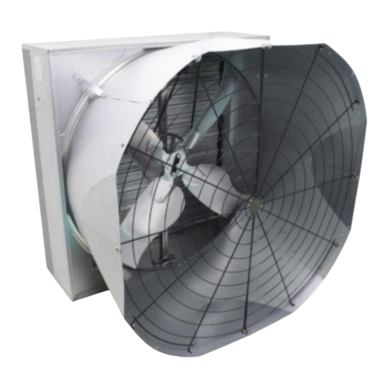
Air extraction fan
Hide thumbs
Also See for EC52:
- Manual for use and maintenance (45 pages) ,
- Assembly manual (36 pages) ,
- Manual for use and maintenance (56 pages)

Related Manuals for Munters EC52


Summary of Contents for Munters EC52
- Page 1 Assembly manual Spare part list + Assembling guideline Air extraction fan Models: EC52 - EC50 Ag/MIT/ImEN-2712-02/19 Rev 1.2...
- Page 2 Munters Italy S.p.A. reserves the right to effect modifications to the apparatus in accordance with technical and legal developments and to make alterations to specifications, quantities, etc., for production or other reasons, subsequent to publication.
-
Page 3: Table Of Contents
CONTENTS 1. SPARE PART LIST EC52 ................4 EC52 exploded view ....................4 Spare parts EC52 ..................... 7 2. ASSEMBLING TOOLS ................18 3. ASSEMBLING GUIDELINES ..............21 HOUSING ASSEMBLING ..................21 CENTRIFUGAL SYSTEM AND PULLEY TO PROPELLER ASSEMBLING ..24 CENTRIFUGAL MASS TO CENTRAL SUPPORT ASSEMBLING ...... -
Page 4: Spare Part List Ec52
1. SPARE PART LIST EC52 EC52 exploded view © Munters AB, 2020... - Page 5 DETAIL A © Munters AB, 2020...
- Page 6 DETAIL B DETAIL C DETAIL D: ALIGNEMENT OF POSITIONING OF PROPELLER SHUTTER BLADE FLANGE ALIGNEMENT FOR REAR AND FLANGE FLANGES © Munters AB, 2020...
-
Page 7: Spare Parts Ec52
Spare parts EC52 Picture Description Q.ty ROUND SAFETY MESH CONE SECTOR THREADED BUSH M8X12.5 POP UP RIVET 6.4X8 TOP PANEL © Munters AB, 2020... - Page 8 Ø8X32 WASHER HEX SCREW M8X16 MOTOR HOOK FOR SPRING RUBBER FOR CABLE PLASTIC TIE ROD © Munters AB, 2020...
- Page 9 CENTRAL PLASTIC BEARING RIGHT PLASTIC BEARING RIGHT SHUTTER BLADE PLASTIC BEARING LEFT METAL CLIP FOR MESH Ø6,3×19 SELF-TAPPING SCREW © Munters AB, 2020...
- Page 10 PYRAMIDAL SAFETY MESH** CENTRAL PLASTIC BEARING LEFT CENTRAL SHUTTER BLADE COVER PLATE SIDE PANEL BOTTOM PANEL © Munters AB, 2020...
- Page 11 CONVEYOR V-BELT M6X16 HEX SCREW Ø6×24 WASHER M6 HEX NUT THICK Ø6 SPRING WASHER © Munters AB, 2020...
- Page 12 CONE BRACKETS HEXAGON SCREW M8X20 REAR FIXED FLANGE W/BUSH HEX SCREW M8X30 PLAIN WASHER D8X24 PROPELLER FLANGE W/ BUSHES © Munters AB, 2020...
- Page 13 PROPELLER M8 HEX NUT HEX NUT M6 WITH FLANGE HUB WITH AXLE M6×30 HEX SCREW CENTRAL PULLEY © Munters AB, 2020...
- Page 14 WATERPROOF DISTANCE PIECE CENTRAL SUPPORT PLASTIC OVAL PLATE M10×30 SCREW EXT TOOTHED WASHER D10.5X18 M10 HEX NUT © Munters AB, 2020...
- Page 15 FRONT FLANGE M25 HEX NUT HEX SOCKET HEAD CAP SCREW M8X16 THREADED BUSH M8X17.5 CENTRIFUGAL SYSTEM PLAIN WASHER D8X16 © Munters AB, 2020...
- Page 16 SPRING WASHER D8 HEX SOCKET HEAD CAP SCREW M8X30 PLASTIC FORK BRASS PIN M6 HEX NUT HEXAGONAL AXLE © Munters AB, 2020...
- Page 17 WARNING STICKER A-1997 35X210 WARNING STICKER B-1997 70X105 PRODUCT LABEL G-1998 95X115 NO HIGH PRESSURE STICKER 42X118 MUNTERS PROTECT STICKER 70X46 * References not appearing in the exploded view. ** Mandatory in EU under 2.7 m. © Munters AB, 2020...
-
Page 18: Assembling Tools
2. ASSEMBLING TOOLS Ref. Picture Description Q.ty RIVETING MACHINE RAC171 INSERTING MACHINE KJ 45 PNEUMATIC SCREWDRIVER 17mm SPANNER 10mm LONG SPANNER © Munters AB, 2020... - Page 19 13mm LONG SPANNER 6mm LONG ALLEN SPANNER 36mm SPANNER PHILLIPS SCREW HEAD ADAPTOR 13mm RING SPANNER SMALL HAMMER © Munters AB, 2020...
- Page 20 10mm COMBINATION SPANNER SCREWDRIVER RATCHET DRIVE EXTENSION 17MM COMBINATION SPANNER 10MM ALLEN KEY © Munters AB, 2020...
-
Page 21: Assembling Guidelines
Insert Venturi into the housing on the right side as in the picture. Fix Venturi to bottom panel with qty. 4 pop rivets (ref. 4). Then fix Venturi to each side panels with qty. 4 pop rivets (ref. 4). © Munters AB, 2020... - Page 22 Fix it to side panels with qty. 3 pop rivets for side. Fix it to Venturi with qty. 4 pop rivets (ref. 4). Place the threaded bushes (ref. 60) in correspondence of proper holes around housing. Qty. threaded bushes for each panel. © Munters AB, 2020...
- Page 23 (ref. 3/Assembling tools) in order to fix the central support to the top and bottom panels. Place the qty. 2 threaded bushes (ref. 3) on the top panel by using inserting machine (ref.2/ Assembling Tools). © Munters AB, 2020...
-
Page 24: Centrifugal System And Pulley To Propeller Assembling
CENTRIFUGAL SYSTEM AND PULLEY TO PROPELLER ASSEMBLING Take the pulley (ref. 41) and insert qty. 4 M6x30 screws (ref. 40) on external part of it. Turn the pulley upside down and place the hub (ref. 39) on it. © Munters AB, 2020... - Page 25 Place the v-belt (ref. 25) on the central pulley. Before assembling the propeller make sure that the hub is oriented as shown in the picture. The 4 highlighted holes are used to fix the propeller to the hub. © Munters AB, 2020...
-
Page 26: Centrifugal Mass To Central Support Assembling
CENTRIFUGAL MASS TO CENTRAL SUPPORT ASSEMBLING Insert the hexagonal axle (ref. 59) in the front flange (ref. 48). This operation will be easier if the hexagonal axle surface will be lubricated with silicon or spray lubricant. © Munters AB, 2020... - Page 27 Fix the hexagonal axle by using qty. 1 D8x32 washer (ref. 6), qty. 1 D8 spring washer (ref. 54) and qty. 1 M8x20 hex screw (ref. 31). Tighten them by means of a 13mm ring spanner (ref. 10/ Assembling tools). © Munters AB, 2020...
- Page 28 Fix the complete assembly to the rear fixed flange w/bush with qty. 6 M8x16 hex socket head cap screws (ref. 50) and qty. 6 M8 hex nuts (ref. 37). Tighten them with a closing torque of 20 Nm. © Munters AB, 2020...
- Page 29 (ref. 31) and screw it on thread present on hexagonal axle. Tighten the screws by means of a 13mm ring spanner (ref. 10/Assembling tools). Place the rubber grommet (ref. 10) on the left side panel for electric cable protection. © Munters AB, 2020...
-
Page 30: Shutter Blades Assembling
10 mm combination spanners (ref. 12/ Assembling tools). Insert the plastic bearing with spring (ref. 12 and 19) on the central shutter blade (ref. 20). “DX” is for right side, “SX” is for left side. © Munters AB, 2020... - Page 31 (ref. 57). To insert the pin use a small hammer (ref. Assembling tools). Insert qty. 9 shutter blades (ref. 14) in the free slots of the housing then place horizontally. © Munters AB, 2020...
- Page 32 By means of a screwdriver (ref. 13/Assembling tools) insert the cover plate over the fan housing. Fix the cover plate on each side by using the 6.3×19 screws (ref. 17) with a pneumatic screwdriver (ref. 3/ Assembling tools). © Munters AB, 2020...
-
Page 33: Ec52 Cone Discharge Assembling
“Trummy 2” manufactured by Fag or the “Ten-Sit” manufactured by Sit. EC52 CONE DISCHARGE ASSEMBLING Assemble the cone sectors (ref. 2) as shown in the pictures, inserting the wings of the first sector in the slots of the second one. - Page 34 1 M6 nut (ref. 28) for the external side of the cone. Repeat the operation for each of the 12 spokes of the mesh. Tighten the screws by using two 10 mm combination spanners (ref. 12/Assembling tools) or similar 10mm tool. © Munters AB, 2020...
-
Page 35: Ec50 Cone Discharge Assembling
Repeat the operation for each of the 12 spokes of the mesh. Fix the cone bracket (ref. 30) to the discharge cone by using qty. 1 M6x16 screw (ref. 26) and qty. 1 M6 nut (ref. 28) © Munters AB, 2020... -
Page 36: Cone Assembling To Fan
Fix the discharge cone to the conveyor with qty. 1 6.3×19 screws (ref. 17) and qty. 1 M6x16 screw (ref. 26) with qty. 1 D6 spring washer (ref. 29) with qty. 1 M6 nut (ref. 28) for the internal side. © Munters AB, 2020... -
Page 37: Optional Pyramidal Shape Mesh Assembling
Fix it to the panels by means of qty. 10 metal clips (ref. 16) and qty. 10 D6.3x19 screws (ref. 17). Fix it by using a pneumatic screwdriver (ref. 3/ Assembling tools) and its proper adapter (ref. 9/ Assembling tools). © Munters AB, 2020... -
Page 38: Spare Part List Ec50
4. SPARE PART LIST EC50 EC50 exploded view © Munters AB, 2020... - Page 39 DETAIL A © Munters AB, 2020...
- Page 40 DETAIL C DETAIL D DETAIL D: ALIGNEMENT OF POSITIONING OF PROPELLER SHUTTER BLADE FLANGE ALIGNEMENT OF REAR AND FRONT FLANGES © Munters AB, 2020...
-
Page 41: Spare Parts Ec50
RUBBER FOR CABLE PLASTIC TIE ROD CENTRAL PLASTIC BEARING RIGHT PLASTIC BEARING RIGHT SHUTTER BLADE PLASTIC BEARING LEFT METAL CLIP FOR MESH Ø6.3×19 SELF-TAPPING SCREW PYRAMIDAL SAFETY MESH CENTRAL PLASTIC BEARING LEFT CENTRAL SHUTTER BLADE COVER PLATE © Munters AB, 2020... - Page 42 REAR FIXED FLANGE W/BUSH HEX SCREW M8X30 PLAIN WASHER D8X24 PROPELLER FLANGE W/ BUSHES PROPELLER* M8 HEX NUT HEX NUT M6 WITH FLANGE HUB WITH AXLE M6×30 HEX SCREW CENTRAL PULLEY WATERPROOF DISTANCE PIECE CENTRAL SUPPORT PLASTIC OVAL PLATE © Munters AB, 2020...
- Page 43 M8X16 HEX SOCKET CAP SCREW THREADED BUSH M8X17.5 CENTRIFUGAL SYSTEM PLAIN WASHER D8X16 SPRING WASHER D8 M8X30 HEX SOCKET CAP SCREW PLASTIC FORK BRASS PIN HEX NUT M6 HEXAGONAL AXLE * References change depending on the configuration utilized. © Munters AB, 2020...
- Page 44 Phone +90 262 7513 750, info@muntersform.com, Phone +1 517 676 7070, aghort.info@munters.com, Export & Other countries Phone +39 0183 5211, info@munters.it Munters reserves the right to make alterations to specifications, quantities, etc., for production or other reasons, subsequent to publication © Munters AB, 2020...
Need help?
Do you have a question about the EC52 and is the answer not in the manual?
Questions and answers