Munters EM50 Assembly Manual
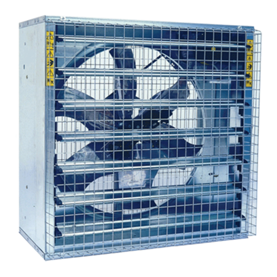
Air extraction fan
Hide thumbs
Also See for EM50:
- Use and maintenance manual (41 pages) ,
- Manual for use and maintenance (30 pages) ,
- Manual for use and maintenance (63 pages)

Subscribe to Our Youtube Channel
Related Manuals for Munters EM50


Summary of Contents for Munters EM50
- Page 1 EM50 Assembly manual Spare part list + Assembling guideline EM50 Air extraction fan Ag/MIT/IGB-2208-09/14 rev 1.6...
-
Page 2: Assembly Manual
Munters Italy S.p.A. reserves the right to effect modifications to the apparatus in accordance with technical and legal developments and to make alterations to specifications, quantities, etc.,for production or other reasons, subsequent to publication. - Page 3 Index chapter page SPARE PART LIST EM50 exploded view Motor exploded view ASSEMBLING TOOLS ASSEMBLING GUIDELINE Housing assembling Centrifugal system and pulley to propeller assembling Shutter blades assembling Safety meshes assembling CE kit assembling Pyramidal shape mesh assembling All the components and spare parts MUST be storaged in dry and clean WARNING environment.
-
Page 4: Spare Part List
Spare part list © Munters AB, 2018... - Page 5 Spare part list Ref. Picture Description Q.ty GROUP1: BODY SAFETY MESHES 670X1,338 23X89 GALV. CENTRAL SUPPORT GALV. COVER PLATE GALV. SIDE PANEL 515X1,367X0.8 GALV TOP PANEL 549X1,457X1 GALV. VENTURI 1,425X1,425 GALV. BOTTOM PANEL 549X1,457X1 GALV. PVC TIE-ROD © Munters AB, 2018...
- Page 6 SHUTTER BLADE GALV. 1.12 CENTRAL SHUTTER BLADE GALV. 1.13 LEFT SIDE SHUTTER BEARING ASSEMBLY 1.14 LEFT SIDE SHUTTER BEARING ASSEMBLY WITH SPRING 1.15 EUROEMME STICKER 24.6X180 1.16 WARNING STICKER A-1997 35X210 1.17 WARNING STICKER B-1997 70X105 © Munters AB, 2018...
- Page 7 Chapter1 Spare part list 1.18 PRODUCT LABEL G-1998 95X115 1.19 NO HIGH PRESSURE STICKER 42X118 GROUP2: PULLEY CENTRAL PULLEY GROUP3: BELT V-BELT 88-2270 GROUP4: MOTOR SEE MOTOR TABLE (p.10) GROUP5: PROPELLER PROPELLER STAINLESS STEEL/PRECOATED/GALV. © Munters AB, 2018...
- Page 8 Purpose: to fix the propeller to the hub HEXAGON SOCKET HEAD CAP SCREW M8X55 UNI 5931 TOOTHED WASHER D8.4X15 UNI 6798 PLAIN WASHER D8.4X17 UNI 659 TICK HEXAGON NUT M8X8 UNI 5587 Purpose: to fix the centfugal system to the propeller © Munters AB, 2018...
- Page 9 Purpose: for cover plate and wire meshes assembling. PLASTIC CLIP MESHES 7.14 Purpose: to fix the safety meshes to the housing. RUBBER GROMMET 7.15 Purpose: to protect the electric cable on the side panel in correspondence with the motor slot. © Munters AB, 2018...
- Page 10 PLASTIC SAFETY PROTECTION FOR MOTOR PULLEY AND FIXING CLIP SELF TAPPING HEX SCREW D6.3X19 PYRAMIDAL SAFETY MESH KIT PYRAMIDAL SAFETY MESH SELF TAPPING HEX SCREW D6.3X19 METAL CLIPS Purpose: to fix the pyramidal safety mesh to the housing. © Munters AB, 2018...
- Page 11 HEXAGON SCREW M8X20 UNI 5739 Models: 1.5Hp - 50/60Hz HEXAGON SCREW M8X20 UNI 5739 MOTOR PLATE 80X256X3 GALV. TICK HEXAGON NUT M8X8 UNI 5587 PLAIN WASHER D6.7X24 UNI 659 SPRING WASHER D6,4X11,4 UNI1751 HEXAGON SCREW M6X16 UNI 5739 © Munters AB, 2018...
- Page 12 Chapter1 Spare part list HOLES FOR MOTOR = Holes for 1.0hp motors = Holes for 1.5hp motors © Munters AB, 2018...
- Page 13 Assembling tools Ref. Picture Description Q.ty RIVETING MACHINE RAC171 INSERTING MACHINE KJ 45 PNEUMATIC SCREWDRIVER 17mm SPANNER 10mm LONG SPANNER 13mm LONG SPANNER 6mm LONG ALLEN SPANNER © Munters AB, 2018...
- Page 14 Chapter2 Assembling tools 36mm SPANNER PHILLIPS SCREW HEAD ADAPTOR 13mm SPANNER SMALL HAMMER 10mm SPANNER SCREWDRIVER RATCHET DRIVE EXTENSION © Munters AB, 2018...
- Page 15 (ref.7.1/Bolts&nuts) for each edge by using riveting machine (ref.1/Assembling Tools). Insert Venturi (ref.1.6/Body) into the housing on the right side as in the picture. Fix Venturi to bottom panel and then to side panels with qty.1 pop rivets for side. © Munters AB, 2018...
- Page 16 The propeller central support (ref.1.2/Body) shall be fixed to housing by means of qty. 4 screws, qty. 2 oval plates, qty. 4 toothed washers and qty. 4 nuts (ref.7.4/Bolts&nuts). Place the oval plates between propeller central support and panels. © Munters AB, 2018...
- Page 17 CENTRIFUGAL SYSTEM AND PULLEY TO PROPELLER ASSEMBLING Place the pulley on the hub and insert the screws (ref.7.5/Bolts&nuts). Turn the pulley plus the hub upside down, insert and fix the flanged nuts (ref.7.5/Bolts&nuts) over the screws. © Munters AB, 2018...
- Page 18 Fix the screws, washers and nuts (ref.7.6/Bolts&nuts) in order to fix the propeller. Tighten the nuts by using pneumatic screwdriver (ref.3/ Assembling tools). Place bolts (ref.7.7/Bolts&nuts) on the centrifugal system (ref.6.1/Centrifugal system) and then place it on the propeller. © Munters AB, 2018...
- Page 19 SHUTTER BLADES ASSEMBLING Insert plastic bearings (ref.1.9-1.13/Body) on shutter blades (ref.1.11/Body) and plastic bearings with spring (ref.1.10-1.14/Body) on central shutter blade (ref.1.12/Body). Both plastic bearings are marked with SX for left side and with DX for right side. © Munters AB, 2018...
- Page 20 Insert the free terminal of the spring on the hook. Repeat this operation for the other side. Insert all the shutter blades on the fan housing and then place the fan horizontally. Place the pvc tie-rod (ref.1.8/Body) on plastic bearing pivots. © Munters AB, 2018...
- Page 21 Fix the qty. 6 screws (ref.7.13/Bolts&nuts) on the fan side (qty. 3 for each side are required). Fix the screws (ref.7.13/Bolts&nuts) with the plastic clips (ref.7.14/Bolts&nuts) in correspondence of the propeller central support on the top panel and the bottom panel. © Munters AB, 2018...
- Page 22 (ref.8.4/Optional kits). PYRAMIDAL SHAPE MESH ASSEMBLING Put the pyramidal shape mesh (ref.8.5/Optional kits) on the fan as in the picture. The rectangular holes must be positioned horizontally. © Munters AB, 2018...
- Page 23 Fix it to the bottom and top panels by means of qty. 6 metal clips and qty. 6 screws (ref.8.6/Optional kits). The metal clips must be fixed in the position as in the picture. Fix it by using a pneumatic screwdriver (ref.3/ Assembling tools). © Munters AB, 2018...
- Page 24 Phone +90 262 7513 750, info@muntersform.com, Phone +1 517 676 7070, aghort.info@munters.com, Export & Other countries Phone +39 0183 5211, info@munters.it Munters reserves the right to make alterations to specifications, quantities, etc., for production or other reasons, subsequent to publication. © Munters AB, 2018...
Need help?
Do you have a question about the EM50 and is the answer not in the manual?
Questions and answers