Munters EM52 Manual For Use And Maintenance
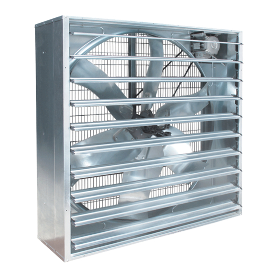
Air extraction/circulation fan
Hide thumbs
Also See for EM52:
- Manual for use and maintenance (56 pages) ,
- Assembly manual (26 pages) ,
- Manual for use and maintenance (63 pages)

Subscribe to Our Youtube Channel
Related Manuals for Munters EM52


Summary of Contents for Munters EM52
- Page 1 EM52 Manual for use and maintenance + CE Declaration of conformity EM52 Air extraction/circulation fan Ag/MIT/UmGB-2134-08/13 rev 1.0...
- Page 2 Munters Italy S.p.A. reserves the right to effect modifications to the apparatus in accordance with technical and legal developments.
- Page 3 4.2 Non-permitted conditions of use INSTALLATION 5.1 Choice of site and checking installation requirements 5.2 Installing Series EM fans 5.3 Connection to the electrical system 5.4 Tests and checks before startup COMMISSIONING 6.1 Control devices 6.2 Instructions for machine use © Munters AB, 2013...
- Page 4 8.3 Belt tensioning check up (only EM models) 8.4 Replacement of propeller 8.5 Replacement of central pulley 8.6 Replacement of shutter bearing assembly 8.7 Fan bearing lubrication 8.8 Replacement of shutter opening device (centrifugal system) SPARE PART LIST WARRANTY © Munters AB, 2013...
-
Page 5: Ce Declaration Of Conformity
WITH PARTICULAR REFERENCE TO THE FOLLOWING PROvISIONS: UNI EN 953:2009, UNI EN ISO 12100:2010, UNI EN ISO 12499:2009, UNI EN ISO 13857:2008, CEI EN 60204-1:2006 (CEI 44-5), UNI EN ISO 5801:2009 Chiusavecchia, 15 August 2013 Marco Scomparin Legal representative © Munters AB, 2013... -
Page 6: Attached Technical Documentation
The information contained herein has been prepared by qualified experts within Munters. While we believe the information is accurate and complete, we make no warranty or representation for any particular purposes. The information is offered in good faith and with the understanding that any use of the units or accessories in breach of the directions and warnings in this document is at the sole discretion and risk of the user. -
Page 7: Safety Aspects
Unauthorized tampering/replacement of one or more parts of the machine, or the use of accessories, tools or materials other than those recommended by the WArNINg manufacturer, are prohibited and release the manufacturer from all liability. © Munters AB, 2013... -
Page 8: General Safety Instructions
(emergency system activated and electricity and hydraulic fluid WArNINg isolated). At the end of maintenance operations, the guards which were removed must be replaced correctly. © Munters AB, 2013... - Page 9 1 Dimensions and positioning in accordance with the instructions Guard of fixed type made of metal Outlet side of fan in the standard UNI EN 13857. mesh. Removable only by means of special tool fig. 2 © Munters AB, 2013...
-
Page 10: Residual Risks
(danger resulting from the presence of live parts), the level of voltage present, the prohibition of tampering by unauthorized personnel and the prohibition on the use of liquids on electrical apparatus in the event of fire. © Munters AB, 2013... - Page 11 Fan model Sound pressure level Lp [dB(A)] EM52 - 2.0hp A measurement has been made of the noise produced by the machine during normal operation in order to calculate the equivalent level in conditions of normal use. These values are shown in the above table.
-
Page 12: Before Using
• propeller with six blades* in stainless, precoated or galvanised steel; blades are fixed to the propeller by high-strength pop rivets; • asynchronous three-phases motor; 50 or 60 Hz; B3 form; F class winding insulation, IP55 protection class; single-speed; • centrifugal operated shutter opening device. * Number may vary according to fan model. © Munters AB, 2013... -
Page 13: Operating Conditions
• use in the event of faults and/or tampering with the installed safety devices; • use by personnel not specifically trained; • installation of the fan for extraction or circulation under pressure; • use contrary to existing regulations; • incorrect installation differing from instructions given in this manual; © Munters AB, 2013... - Page 14 Interference with the command and control circuits is prohibited: such operations WArNINg could cause damage to the equipment and serious danger to the operator. © Munters AB, 2013...
- Page 15 Emission into the atmosphere of harmful particles or gases must be contained within the limits established by current regulations. The fan has been designed and built in such a way that it CANNOT operate in a WArNINg classified area, according to directive 1999/92/EC. © Munters AB, 2013...
-
Page 16: Choice Of Site And Checking Installation Requirements
The area adjacent to the fan in the premises from which air is being extracted must be kept clear to allow the air to exit freely. It is also prohibited for anyone to remain in this area, because of the presence of organic gases and dust which may be present in the airflow. © Munters AB, 2013... - Page 17 When the outer frame is properly built-in, i.e. perfectly level and upright, insert the fan, screwing four M8 bolts type 8.8 (not supplied with the fan) into the threaded inserts provided on the sides of the bodywork, two per side. fig. 6 © Munters AB, 2013...
-
Page 18: Connection To The Electrical System
Do not supply power to the fan during installation stage. Installer must issue a declaration of correct installation in accordance with WArNINg applicable legislation in the country of use. © Munters AB, 2013... - Page 19 • check that the protection devices (fuses, magnetothermic switches) are correctly sized, and that the phases are connected in the correct order: check that the fan rotates in the direction of the arrow shown on the driven pulley (see fig. 9). © Munters AB, 2013...
- Page 20 • check the fan visually, verifying that there are no particular mechanical irregularities or foreign bodies inside the structure; • check that the protective structures (fixed guards made of metal mesh) are correctly positioned and fixed; © Munters AB, 2013...
- Page 21 • check that the guards inside the electrical panel are correctly positioned and fixed; • check that the safety devices are receiving power and are active, and check their effectiveness. After this series of checks has been carried out, the fan is ready for its first startup. © Munters AB, 2013...
-
Page 22: Control Devices
In the event that the fan does not need to be used for an extended period of time, the following stop procedure must be used: • operate the stop button • operate the emergency stop button; • open the main isolator switch (position “0”) on the electrical panel and attach a padlock to the actuator. © Munters AB, 2013... - Page 23 After an emergency stop, the operating cycle must be reset by following the procedure described below: • reset the actuator by which the emergency stop command was given (by turning the relative mushroom button); • for an exact reset sequence, refer to the instructions given in section 6.1. © Munters AB, 2013...
-
Page 24: Technical Data
Weight of fully equipped fan* [kg] Airflow at 0 Pa /h [cfm] 43,000 [25,300] Airflow at 50 Pa /h [cfm] 33,900 [19,900] Airflow at 80 Pa /h [cfm] 27,600 [16,200] Airflow at 100 Pa /h [cfm] 19,200 [11,300] © Munters AB, 2013... -
Page 25: Motor Specifications
[rpm] IEC protective class of electric motor IP55 Electric motor winding insulation grade 7.3 Motor specifications Code Nominal Power Phases Speed Frequency voltage Current [Hp] [Hz] 1,500 single 230/400 6.1/3.5 1,400 1,500 single 230/400 5.5/3.2 1,680 © Munters AB, 2013... -
Page 26: Maintenance
15 mm, when pushed in by thumb. Tighten fan belt after the fan has been running for 3 days. Without adjusting the WArNINg tension, transmission components can wear out early. © Munters AB, 2013... - Page 27 1. Open shutter by hand and take away the pin, which connects central shutter blade to centrifugal system. fig. 13 2. Loosen motor to propeller v-belt from pulleys throat; 3. unscrew the fixing nut. fig. 14 © Munters AB, 2013...
- Page 28 To replace the central pulley follow the same procedure of the propeller replacement (see section 8.4). 8.6 Replacement of shutter bearing assembly 1. open shutter by hand and take away the pin, which connects central shutter blade to centrifugal system; fig. 17 © Munters AB, 2013...
-
Page 29: Fan Bearing Lubrication
3. do the reverse procedure to replace the shutter opening device and put back the pin, which connects central shutter blade to centrifugal system. fig. 20 © Munters AB, 2013... - Page 30 • unpack the components to permit air circulation between the surfaces; NoTE • stack the components to allow water to drain out; • keep the packed components in such way to prevent moisture contact with the galvanized surface. © Munters AB, 2013...
-
Page 31: Spare Part List
Spare part list EM52 fig.15 © Munters AB, 2013... - Page 32 HExAGON SCREW M6x30 UNI 5739 CENTRAL PULLEY WATERPROOF DISTANCE PIECE THIN HExAGON NUT M25x10 UNI 5589 TICK HExAGON NUT M10x10 UNI 5587 TOOTHED WASHER D10.5x18 UNI 5589 OvAL PLATE HExAGON SOCKET SCREW M10x30 UNI 5923 HOOK FOR SPRING © Munters AB, 2013...
- Page 33 PLAIN WASHER D6x24 UNI 659 + SEAL SELF TAPPING SCREW 6.3x19 DIN 7049 PLASTIC CLIP FOR MESHES PLATE FOR MOTOR SAFETY PROTECTION METAL SAFETY PROTECTION FOR MOTOR MOTOR PULLEY PITCH DIAMETER AND HOLE 2HP - 3-PHASE 50HZ 60HZ 95/24 80/24 © Munters AB, 2013...
-
Page 34: Warranty And Technical Assistance
Munters plant was required: if this is not done, the user is fully responsible for the damage which they could suffer. - Page 35 Requests for technical assistance and spare parts must be made directly to the manufacturer, at the following address: Munters Italy S.p.A Strada Piani, 2 18027 Chiusavecchia (IM), Italy Tel: +39 0183 52 11 Fax: +39 0183 521 333 info@munters.it © Munters AB, 2013...
- Page 36 Euroemme EM52 extraction fans are developed and produced by Munters Italy S.p.A., Italy ® www.munters.com Australia Munters Pty Limited, Phone +61 2 8843 1594, Brazil Munters Brasil Industria e Comercio Ltda, Phone +55 41 3317 5050, Canada Munters Corporation Mason, Phone +1 517 676 7070, China Munters Air Treatment Equipment (Beijing) Co.
Need help?
Do you have a question about the EM52 and is the answer not in the manual?
Questions and answers