Advertisement
Quick Links
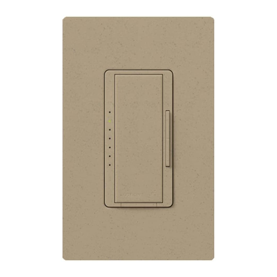
Wireless
®
Halogen / Incandescent Dimmer
with Radio Frequency Receiver
MRF2-600M
120 V
60 Hz 600 W
(Single-Pole or Multi-Location)
030-1126
Rev. A
Important Notes:
Please read before installing.
1.
Install in accordance with all national and local electrical codes.
2.
When no "grounding means" exist within the wallbox, then the NEC
allows a Dimmer without a grounding connection to be installed as a replacement, as long as
a plastic, noncombustible wallplate is used. For this type of installation, twist a wire connector
onto the green ground wire or remove the green ground wire on the Dimmer and use an ap-
pro pri ate wallplate such as Claro
or Satin Colors
series wallplates by Lutron
®
®
3.
Do not paint the Dimmers or the Companion Dimmers.
4.
The Dimmers are not compatible with standard 3-way or 4-way switches. Use only with Lutron
Companion Dimmers.
5.
In any 3-way/4-way circuit use only one Dimmer with up to 9 Companion Dimmers.
6.
Do not use where the total load is greater than the rating indicated in the Derating Chart below.
7.
Do not use where total load is less than 50 W / VA.
8.
Operate between 32 °F (0 °C) and 104 °F (40 °C).
9.
For indoor use only.
10. It is normal for the Dimmers to feel warm to the touch during operation.
11. Recommended minimum wallbox depth is 2.5 in (64 mm).
12. Maximum wire length between the Dimmers and the furthest Companion Dimmer is 250 ft (76 m).
13. Clean with a soft damp cloth only. Do not use any chemical cleaners.
14. DO NOT mix MRF and MRF2 lighting controls products within the same system. Products are
NOT compatible, contact Lutron Technical Support Center.
15. Controls must be mounted vertically. See stamp on control for correct positioning.
16. DO NOT wire while circuit breaker is on. Permanent damage to the Dimmer may result.
17. DO NOT use Incandescent / Halogen or Electronic Low-voltage Dimmers for Magnetic Low-
voltage lighting.
18. Up to 10 Maestro Wireless controls can be configured to work together.
Multigang Installations
When installing more than one control in the same wallbox, the maximum load capacity is reduced.
No derating is required for Companion Dimmers. Refer to the Derating Chart below.
Model
Type of Load
MRF2-
Halogen /
600M
Incandescent
*The maximum lamp wattage is determined by the efficiency of the transformer, with 70%–85% as typical. For actual
transformer efficiency, contact either the fixture or transformer manufacturer. The total VA rating of the transformer(s)
shall not exceed the VA rating of the dimmer.
Dimming Rocker
Tap Button Options.
Press to brighten.
•
Tap once when
Press to dim.
the Dimmer is off:
Lights brighten smoothly
LEDs
to preset intensity.
Light level indicators.
•
Tap once when the
FASS ™ - Front
Dimmer is on: Lights
dim smoothly to off.
Accessible Service Switch
•
Tap twice quickly:
Important Notice:
Lights brighten rapidly
To replace the bulb, power may be
to full intensity.
conveniently removed by pulling the
FASS switch out on the Dimmer.
•
Press and hold when
the Dimmer is on:
For any procedure other than
Each time the Dimmer is
routine bulb replacement, power
turned off, delayed fade
must be disconnected at the
to OFF can be activated.
main electrical panel.
As the Tap Button is
held, the current LED
will begin to flash. This
flashing LED represents
20 seconds of delay
before the lights fade
to OFF.
Multiple Dimmer Applications
If multiple Maestro Wireless Dimmers are set up to the same Wireless Controller, they will perform
as follows:
•
Pressing the On Button on the Wireless Dimmers
Controller will cause all Dimmers to turn on fully.
•
Pressing the Off Button on the Wireless Controller will
cause all Dimmers to turn off completely.
•
Pressing the Raise Button on a Wireless Controller will
cause the Dimmer to turn on and gradually
increase the light level.
•
Pressing the Lower Button on a Wireless Controller will
cause the Dimmer to gradually decrease
light level.
Lutron Electronics Co., Inc.
7200 Suter Road
Coopersburg, PA 18036-1299, U.S.A.
English
Set-Up
Important: Set up Wireless Controller to a Dimmer/Switch before use.
1
Press and hold the Dimmer/Switch's Tap Button (Figure 1) for approximately 6 seconds.
Once the LED(s) start to blink slowly,
release the Tap Button.
2
Press and hold the Off Button on the Wireless Controller (Figure 2) for approximately
6 seconds.
3
Once the Dimmer/Switch learns the Wireless Controller, the Dimmer/Switch's LED(s)
and load will flash 3 times and it will exit Set-Up mode.
4
Repeat steps 1 —3 to set up multiple Wireless Controllers to a single Dimmer or Switch.
2008, Article 404.9
®
Repeat steps 1 —3 to set up a single Wireless Controller to multiple Dimmers/Switches.
5
Pressing the Preset Button will cause each Dimmer/Switch to return to it's favorite light setting.
.
®
To save a favorite light setting, adjust all the Dimmers/Switches controlled by a Wireless
Controller to the desired light setting. Then press and hold the Preset Button on the Wireless
Controller for approximately 6 seconds until all LEDs on the Dimmers/Switches stop blinking.
Removing Wireless Controller
To remove a previously set up Wireless Controller tap the Wireless Controller's On button
three times, on the third tap hold for 3 seconds and then tap 3 more times. This will
remove all Dimmers/Switches it was previously setup with.
Single
End of
Middle of
Gang
Gang
Gang
600 W
500 W
400 W
FCC Information:
NOTE: This equipment has been tested and found to comply with the limits for a Class B digital device, pursuant to
part 15 of the FCC rules. These limits are designed to provide reasonable protection against harmful interference in
a residential installation. This equipment generates, uses and can radiate radio frequency energy and, if not installed
and used in accordance with the instructions, may cause harmful interference to radio and television reception, which
can be determined by turning the equipment off and on. The user is encouraged to try to correct the interference by
one or more of the following measures:
• Reorient or relocate the receiving antenna.
• Increase the separation between the equipment and receiver.
• C onnect the equipment into an outlet on a circuit different from that to which the receiver is connected.
• C onsult the dealer or an experienced radio/TV technician for help.
Caution: Changes or modifications not expressly approved by Lutron Electronics Co. could void the user's authority
to operate this equipment.
This device complies with Part 15 of the FCC Rules. Operation is subject to the following two conditions:
(1) This device may not cause harmful interference and
(2) This device must accept any interference received, including interference that may cause undesired operation.
Trouble Shooting
Symptoms
Load does not turn on
or LED(s) on Dimmer/
Switch do not light up.
Light does not respond
to Wireless Controller
When in set-up mode
the LEDs flash when
trying to setup with the
Wireless Controller or
Sensor.
Made and Printed in U.S.A. 10/09 P/N 030-1126 Rev. A
Light
On
Adjust
Off
LUTRON
Figure 2
Figure 1
Possible Causes
•
FASS
switch on the Dimmer/Switch (or Companion Dimmer/Switch) is
™
in the Off position.
•
Light bulb(s) burned out.
•
Breaker is OFF or tripped.
•
Load not properly installed.
•
Wiring error. Call Lutron Technical Support Center.
•
The Dimmer/Switch failed to learn Wireless Controller; see
Set-Up.
•
The Dimmer/Switch has already received and responded to a command
or is already at the Light Setting the Wireless Controller is requesting.
•
The Wireless Controller is outside the 30 ft (9 m)operating range.
•
The Wireless Controller's battery is low.
•
The Wireless Controller's battery is installed incorrectly.
•
The maximum number of Wireless Controllers have been set up to
the Dimmer/Switch, You cannot add any more Wireless Controllers or
Sensors. See Removing Wireless Controllers in Set-Up.
Installation
1
Turning Power OFF
Turn power OFF at circuit break er (or remove fuse).
2
Removing
WARNING
Shock Hazard. May result in serious injury or
Wallplate and Switch
death. Turn off power at circuit breaker before
Remove the wallplate and
installing Dimmer.
switch mounting screws.
Carefully remove the switch from the wall (do not remove the wires).
ADVERTENCIA
3
Identifying the Circuit Type and Tagging the Wire on the COMMON Terminal
of the Switches
AVERTISSEMENT
3a – Single Location Control
One switch controlling a light fixture:
This switch will be a single-pole. The switch will
have insulated wires connected to two screws of the
Ground
same color plus a green ground screw.
(Bare Copper or
Green Wire)
3b – Two-Location Control
Two switches controlling a light fixture:
Ground
Both switches will be 3-way. Each switch will
(bare copper or
have insulated wires connected to three screws
green wire)
plus a green ground screw. One of these wires is
connected to a screw of a different color (not green)
Different colored
or labeled COMMON. Tag this wire on both switches
screw (Common)
to identify when rewiring.
Tag
3c – Three or More-Location Control
Three or more switches controlling a light fixture:
Note: Screw
placement may
Two switches will be 3-way and any others will be
be different on the
4-way. Tag the two 3-way switches as in the Two-
switch.
Location diagram above. The 4-way switch will
Same colored
have insulated wires connected to four screws plus
screw (or marked
a green ground screw. Tag the two same-color
IN or OUT)
insulated wires that are connected to opposite
Ground
colored screws. Follow this procedure for each
Tags
(bare copper
4-way switch.
or green wire)
4
Disconnecting the Switch Wires.
Important Note: The wall switch may have two wires attached to the same screw
(see illustrations below for examples). Tape these two wires together before
disconnecting. When rewiring, connect wires to the Dimmer the same way they
were connected to the switch.
One wire
One
in the
continuous
backwired
wire to the
hole and one
screw.
to the screw.
Screw
Terminals:
Turn screws
to loosen.
5
Wiring
When making wire connections, follow the recommended strip lengths and
combinations for the supplied wire connector.
Note: All wire connectors provided are suitable for copper wire only. For aluminum
wire, consult an electrician.
Wire connector:
Use to join 14 AWG
(1.5 mm
2
) or 12 AWG
(2.5 mm
2
) ground
wire(s) to 18 AWG
(0.75 mm
) Dimmer
2
ground wire.
Twist wire
connector tight.
Peligro de choque. Podría resultar en
lesiones graves o la muerte. Desconecte la
alimentación en el cortacircuito antes de
instalar el Atenuador.
Risque de choc. Peut provoquer des
blessures graves et même la mort.
Coupez le courant au disjoncteur avant
d'installer le gradateur.
Push-in Terminals:
Insert screwdriver.
Pull wire out.
Looped Wire:
Turn screw to
loosen.
Push-in terminals:
Insert wires fully.
Note: Push-in terminals are
for use with 14 AWG (1.5 mm
) solid
2
copper wire only. DO NOT use
stranded or twisted wire.
Screw terminals:
Tighten securely.
Note: Screw terminals are for use
with 12 AWG (2.5 mm
2
) or 14 AWG
(1.5 mm
2
) solid copper wire only.
DO NOT use stranded or twisted wire.
Continued on back
Advertisement

Subscribe to Our Youtube Channel
Related Manuals for Lutron Electronics Maestro Wireless MRF2-600M


Summary of Contents for Lutron Electronics Maestro Wireless MRF2-600M
- Page 1 Turn screws loosen. dim smoothly to off. Accessible Service Switch to loosen. Caution: Changes or modifications not expressly approved by Lutron Electronics Co. could void the user’s authority • Tap twice quickly: to operate this equipment. Important Notice: Lights brighten rapidly This device complies with Part 15 of the FCC Rules.
- Page 2 Controller is installed, not before. Maestro, Maestro Wireless, The Sunburst Logo and Satin Colors are registered trademarks and FASS is a trademark of Lutron Electronics Co., Inc. NEC is a registered trademark of National Fire Protection Association, Quincy, Massachusetts. © 2009 Lutron Electronics Co., Inc.
Need help?
Do you have a question about the Maestro Wireless MRF2-600M and is the answer not in the manual?
Questions and answers