
Related Manuals for Wacker Neuson 50Z3


Summary of Contents for Wacker Neuson 50Z3
- Page 1 Operator’s Manual Track excavators Model E05-01/02/04/05/08/09 Edition Language Article number 1000127717...
- Page 2 01/2010 01/2011 01/2012 08/2013 Copyright – 2012 Wacker Neuson Linz GmbH, Hörsching Printed in Austria All rights reserved No part of this publication may be reproduced, translated or used in any form or by any means – graphic, electronic or mechanical including photocopying, recording, taping or information storage or retrieval systems – without prior permission in writing from the manufacturer.
-
Page 3: Table Of Contents
Working near overhead electric lines .............. 2-12 Gas, dust, steam, smoke ................. 2-13 Hydraulic system ..................... 2-13 Noise ....................... 2-13 Oil, grease and other chemical substances ............. 2-13 Using the quickhitches in water ............... 2-13 Battery ......................2-14 BA 50Z3/6003 en - Edition 4.3 * Ba5003en4_3IVZ.fm... - Page 4 Cab 50Z3/6003 (up to serial no. AH02781) ............. 3-2 Cab 50Z3 2 / 6003 2 (from serial no. AJ02777) ............3-4 Control elements 50Z3 (up to serial no. AH02781) / 6003 (up to serial no. AH00578) .. Control elements 6003 (serial nos. AH00579 to AH02750) ........3-7 Control elements 50Z3 2 / 6003 2 (from serial no.AJ02777) ........
- Page 5 Battery master switch .................... 3-64 Raising/lowering the cab ..................3-65 Towing the machine ....................3-68 Crane handling the machine .................. 3-69 Loading and transporting the machine ..............3-71 Safety instructions ................... 3-71 BA 50Z3/6003 en - Edition 4.3 * Ba5003en4_3IVZ.fm...
- Page 6 Operation (from serial no. AJ02777) ..............3-98 Vario (6003 option) ....................3-99 Vario operation ....................3-99 Driving across slopes with the Vario feature ............ 3-99 Risk zone of the Vario feature ............... 3-100 BA 50Z3/6003 en - Edition 4.3 * * Ba5003en4_3IVZ.fm...
- Page 7 Proportional controls (option) diagnosis display ............ 4-11 Maintenance Introduction ......................5-1 Safety-relevant parts ....................5-1 Fuel system ......................5-2 Refuelling ......................5-3 Fuel-filling pump (option) (up to serial no. AD04862) ........5-3 BA 50Z3/6003 en - Edition 4.3 * Ba5003en4_3IVZ.fm...
- Page 8 Battery ......................5-38 General maintenance work ..................5-40 Cleaning ......................5-40 General instructions for all areas of the machine ..........5-40 Inside the cab ....................5-40 Cleaning the seat belt ..................5-41 BA 50Z3/6003 en - Edition 4.3 * * Ba5003en4_3IVZ.fm...
- Page 9 Electrical system, model 6003 (from serial no. AH0611) ......... 6-4 Fuse box on instrument panel (up to serial no. AH02750) ........ 6-4 Main fuse box with relays .................. 6-5 Fuse box on instrument panel (from serial no. AJ02777) ........6-5 BA 50Z3/6003 en - Edition 4.3 * Ba5003en4_3IVZ.fm...
- Page 10 Lift capacity table 50Z3 long stick, counterweight (option) ........6-22 Lift capacity table 50Z3 VDS short stick (option) ........... 6-23 Lift capacity table 50Z3 VDS short stick, counterweight (option) ......6-24 Lift capacity table 50Z3 VDS long stick (option) ............ 6-25 Lift capacity table 50Z3 VDS long stick, counterweight (option) ......
- Page 11 Putting into operation ..............3-7, 3-9 Check lists ..................3-15 Putting the machine into operation for the first time ..... 3-14 Safety instructions ................ 3-14 Refuelling ....................5-3 Rotating beacon .................. 3-32 Running-in period ................3-14 BA 50Z3/6003 en - Edition 4.3 * Ba5003en4_3SIX.fm...
- Page 12 Tilting the upper carriage ..............3-97 Track maintenance ................5-33 Ventilation ....................3-33 Ventilation, fresh air ..............3-33 Warranty ....................2-1 Washer system ..................3-36 Tank ....................3-36 Wiper ....................3-36 Working Freeing the machine ..............3-121 Practical hints ................3-121 I-10 BA 50Z3/6003 en - Edition 4.3 * * Ba5003en4_3SIX.fm...
-
Page 13: Notices On This Operator's Manual
• Special equipment and superstructures are not described in this Operator’s Manual. • Wacker Neuson reserves the right to improve the technical standard of our machines without adapting the Operator’s Manual. -
Page 14: Abbreviations/Symbols
This symbol shows the driving direction – for better orientation in figures and graphics. Notice! Unless otherwise specified, all indications made in this Operator’s Manual refer to models 50Z3 / 6003 and 50Z3 2 / 6003 2. BA 50Z3/6003 en – Edition 4.3 * * 5003b110.fm... -
Page 15: Machine Overview
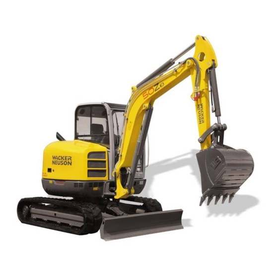
Tank filler inlet Exhaust pipe Eye hook for loading/tying down the machine Rotating beacon (option) Auxiliary hydraulics Tank cover Door arrester Door handle and lock Counterweight (option) Fig. 1: Machine outside views BA 50Z3/6003 en – Edition 4.3 * 5003b110.fm... -
Page 16: Overview Of Model Designations And Trade Names
Yanmar 4TNV98-ZVNS Brief description The machine model 50Z3/6003 is a self-propelled work machine. Get informed on and follow the legal regulations of your country. This machine is a versatile and powerful helper for moving earth, gravel and debris on con- struction sites and elsewhere. -
Page 17: Cab
The cab has been specially designed for protection in case of an accident. • ROPS (Roll Over Protective Structure) and TOPS (Tip Over Protective Structure) tested cab. • FOPS (Falling Object Protective Structure) – option. BA 50Z3/6003 en – Edition 4.3 * 5003b110.fm... -
Page 18: Fields Of Application, Attachments
Easy Lock quickhitch 125 kg (275.58 lbs) 0.164 m³ (5.79 ft³) 50Z3 Easy Lock quickhitch Backhoe bucket 600 mm (23.62 in) 146 kg (321.87 lbs) 0.210 m³ (7.42 ft³) 6003 Easy Lock quickhitch BA 50Z3/6003 en – Edition 4.3 * * 5003b110.fm... - Page 19 253 kg (557.77 lbs) 0.217 m³ (7.66 ft³) 6003 Easy Lock quickhitch Hydraulic hammer NE 28 285 kg (628.32 lbs) 50Z3 Hydraulic hammer NE 36 350 kg (771.62 lbs) 50Z3/6003 Hydraulic hammer NE 42 438 kg (965.62 lbs) 6003 BA 50Z3/6003 en – Edition 4.3 * 5003b110.fm...
-
Page 20: Regulations
• Persons are expected to perform work reliably. • Users have been appointed by the contractor for driving and servicing the earth moving machine. • Get informed on and follow the legal regulations of your country. BA 50Z3/6003 en – Edition 4.3 * * 5003b110.fm... -
Page 21: Ec Declaration Of Conformity For All Machines Delivered Before 29 December 2009
Place of storage of technical documentation: Wacker Neuson Linz GmbH Department: R & D Haidfeldstr. 37 A-4060 Linz-Leonding Linz-Leonding, (date) _ _ _ _ _ _ Ing. Hans Neunteufel (Managing Director) Wacker Neuson Linz GmbH BA 50Z3/6003 en – Edition 4.3 * 5003b110.fm... -
Page 22: Ec Declaration Of Conformity For All Machines Delivered After 29 December 2009
DIN EN ISO 12100-1 and 2, DIN EN 474-1 and 5, DIN EN 14121, DIN EN 3471, DIN EN 13510, EN ISO 3744, EN ISO 3746, DIN EN ISO 3449 Leonding, Thomas Köck, Josef Erlinger, Place, date Responsible for documentation Managing director 1-10 BA 50Z3/6003 en – Edition 4.3 * * 5003b110.fm... -
Page 23: Declaration Of Conformity For Machines Without Ce Mark On The Type Label
DIN EN ISO 12100-1 and 2, DIN EN 474-1 (except 7.3.) and 5, DIN EN 14121, DIN EN 3471, DIN EN 13510, EN ISO 3744, EN ISO 3746, DIN EN ISO 3449 Leonding, Thomas Köck, Josef Erlinger, Place, date Responsible for documentation Managing director 1-11 BA 50Z3/6003 en – Edition 4.3 * 5003b110.fm... - Page 24 Place of storage of technical documentation: Wacker Neuson Linz GmbH Department: R & D Haidfeldstr. 37 A-4060 Linz-Leonding Linz-Leonding, (date) _ _ _ _ _ _ Ing. Hans Neunteufel (Managing Director) Wacker Neuson Linz GmbH 1-12 BA 50Z3/6003 en – Edition 4.3 * * 5003b110.fm...
-
Page 25: Ec Declaration Of Conformity For All Machines Delivered After 29 December 2009
DIN EN ISO 12100-1 and 2, DIN EN 474-1 and 5, DIN EN 14121, DIN EN 3471, DIN EN 13510, EN ISO 3744, EN ISO 3746, DIN EN ISO 3449 Leonding, Thomas Köck, Josef Erlinger, Place, date Responsible for documentation Managing director 1-13 BA 50Z3/6003 en – Edition 4.3 * 5003b110.fm... -
Page 26: Declaration Of Conformity For Machines Without Ce Mark On The Type Label
DIN EN ISO 12100-1 and 2, DIN EN 474-1 (except 7.3.) and 5, DIN EN 14121, DIN EN 3471, DIN EN 13510, EN ISO 3744, EN ISO 3746, DIN EN ISO 3449 Leonding, Thomas Köck, Josef Erlinger, Place, date Responsible for documentation Managing director 1-14 BA 50Z3/6003 en – Edition 4.3 * * 5003b110.fm... -
Page 27: Type Labels And Component Numbers
Cab type label (up to serial no. AH02781) The type label is located on the chassis of the cab, at the upper left beside the door. Fig. 5: Cab type label (from serial no. AJ02777) 1-15 BA 50Z3/6003 en – Edition 4.3 * 5003b110.fm... - Page 28 The type label (arrow) is located on the valve cover (engine). Example: Yanmar 46557 Fig. 6: Diesel engine type label up to serial no. AH00578 Fig. 6: Diesel engine number Fig. 6: Diesel engine type label from serial no. AH00579 1-16 BA 50Z3/6003 en – Edition 4.3 * * 5003b110.fm...
- Page 29 Hydraulic quickhitch Fig. 7: Type label (hydraulic quickhitch) Powertilt with hydraulic quickhitch The type label is located on the rear side of the hydraulic quickhitch fork. Fig. 8: Powertilt type label 1-17 BA 50Z3/6003 en – Edition 4.3 * 5003b110.fm...
-
Page 30: Signs And Symbols
Introduction 1.13 Signs and symbols Overview of adhesive labels 1-18 BA 50Z3/6003 en – Edition 4.3 * * 5003b110.fm... - Page 31 Fig. 12: Direction indicator Meaning Hydraulic oil tank. Use only specified hydraulic fluids. – see chapter 5.21 Fluids and lubricants on page 5-54 Location On the tank cover. Fig. 13: Hydraulic oil 1-19 BA 50Z3/6003 en – Edition 4.3 * 5003b110.fm...
- Page 32 This label describes the functions of the hydraulic quickhitch. – see chapter 3.59 Hydraulic Easy Lock quickhitch (option) on page 3-106. Location On the headliner. 421-2878 1000278864 Fig. 18: Hydraulic quickhitch 1-20 BA 50Z3/6003 en – Edition 4.3 * * 5003b110.fm...
- Page 33 This label describes the pedal and control lever functions (control pattern A). – see chapter 3.50 Control levers/ISO controls: overview on page 3-83 Location On the headliner Controls A = ISO controls B = SAE controls Fig. 23: Controls (A) 1-21 BA 50Z3/6003 en – Edition 4.3 * 5003b110.fm...
- Page 34 The 3rd control circuit is enabled with the button on the right-hand control lever. The status indicator light illuminates. The function is performed with the slide switch on the right-hand control lever. Fig. 28: Cab label 1-22 BA 50Z3/6003 en – Edition 4.3 * * 5003b110.fm...
-
Page 35: Overview Of Safety Labels
Introduction Overview of safety labels 1-23 BA 50Z3/6003 en – Edition 4.3 * 5003b110.fm... - Page 36 Carefully and slowly open the cover only after the tank has cooled down, to release the pressure. Wear suitable protective clothing and goggles to open the cover. Location In the engine compartment. Fig. 32: Rotating V-belt 1-24 BA 50Z3/6003 en – Edition 4.3 * * 5003b110.fm...
- Page 37 On the front window. Meaning Caution, danger of severe or fatal injuries. Stay clear of the machine’s work range during operation. Location On either side of the boom. Fig. 37: Boom operation 1-25 BA 50Z3/6003 en – Edition 4.3 * 5003b110.fm...
- Page 38 • Lower the boom and the stabilizer blade to the ground before leaving the machine, stop the engine, remove the ignition key and fold up the armrest. Location Inside the cab, on the side. Fig. 41: Warnings 1-26 BA 50Z3/6003 en – Edition 4.3 * * 5003b110.fm...
- Page 39 Remove the shatter protection if the machine is transported on an open platform. Location On the shatter protection at the upper left in driving direction. Fig. 47: Removing the shatter protection 1-27 BA 50Z3/6003 en – Edition 4.3 * 5003b110.fm...
-
Page 40: Fire Extinguisher
Check the fire extinguisher at regular intervals, also ensure that it is safely installed. Fig. 48: Fire extinguisher (up to serial no. AH02781) Fig. 49: Fire extinguisher (from serial no. AJ02777) 1-28 BA 50Z3/6003 en – Edition 4.3 * * 5003b110.fm... -
Page 41: Safety Instructions
Warranty claims can be made only if the conditions of warranty have been observed. They are included in the General Conditions of Sales and Delivery for new machines and spare parts sold by the dealers of Wacker Neuson Linz GmbH. Furthermore, the instructions in this Operator’s Manual must be observed. -
Page 42: Designated Use And Exemption From Liability
Neuson GmbH. Wacker Neuson will not be liable for damage resulting from this. • Wacker Neuson Linz GmbH shall not be liable for injury and/or damage to property caused by failure to observe the safety instructions and the Operator’s Manual, and by the negligence of the duty to exercise due care when: •... -
Page 43: General Conduct And Safety Instructions
Wacker Neuson. This also applies to the installation and the adjustment of safety devices and valves, as well as to welding work on load-bearing elements. -
Page 44: Selection And Qualification Of Personnel, Basic Responsibilities
• This also includes the area affected by falling material, equipment or by parts that are thrown out. The risk zone must be extended by 0.5 m (20") in the immediate vicinity of • buildings • scaffolds or • other elements of construction. BA 50Z3/6003 en – Edition 4.3 * * 5003b210.fm... -
Page 45: Safety Instructions Regarding Operation
• When working in buildings or in enclosed areas, look out for in particular: • Height of the ceiling/clearances • Width of entrances • Maximum load of ceilings and floors • Sufficient room ventilation – danger of poisoning. BA 50Z3/6003 en – Edition 4.3 * 5003b210.fm... -
Page 46: Information On Visibility
Operator’s Manual. The operator must observe the local regulations. Do not make any changes or modifications that impair visibility. Otherwise the machine does not meet the requirements for conformity and licensing. BA 50Z3/6003 en – Edition 4.3 * * 5003b210.fm... -
Page 47: Checks When Reversing The Machine
• Ensure that nobody is within the risk zone of the machine when changing the driving direction. • Use the rearview mirrors to reverse with the machine. 2.10 Trailer operation Notice! No trailer operation with this machine. BA 50Z3/6003 en – Edition 4.3 * 5003b210.fm... -
Page 48: Applications With Lifting Gear
The machine operator may give his permission only after the machine is at a standstill and the work attachment no longer moves. BA 50Z3/6003 en – Edition 4.3 * * 5003b210.fm... -
Page 49: Prerequisite For Safe Use
• Raise the control lever base before installing attachments on the stick. • Be careful when coupling attachments to the machine: risk of injury due to crushing and shearing. Ensure that nobody is between the machine and the attachment. BA 50Z3/6003 en – Edition 4.3 * 5003b210.fm... -
Page 50: Safety Instructions For Maintenance
Operator’s Manual, including information on the replacement of parts/partial equipment. These activities may be performed only by a Wacker Neuson workshop. • The machine may not be serviced, repaired or test-driven by unauthorized personnel. • Brief operating personnel/user before beginning special operations and maintenance work. - Page 51 If necessary, wear protective clothing, safety glasses, masks, gloves and ear protectors. • The lock nuts may be used only once and must be replaced by new ones every time they are removed. 2-11 BA 50Z3/6003 en – Edition 4.3 * 5003b210.fm...
-
Page 52: Warning Of Special Hazards
• If no sufficient distance can be kept to overhead electric lines, the machine operator must take other safety measures, for example switching off the current, in agreement with the owner or operator of the lines. 2-12 BA 50Z3/6003 en – Edition 4.3 * * 5003b210.fm... -
Page 53: Gas, Dust, Steam, Smoke
• Apply grease to the lubrication points before using the Easy Lock offset bucket in water. • After using the quickhitch in water, apply grease to the lubrication points to remove all water. • Using the quickhitch in salt water is prohibited. 2-13 BA 50Z3/6003 en – Edition 4.3 * 5003b210.fm... -
Page 54: Battery
• Stop work immediately if a hydraulic hose moves back and forth in an unusual manner. This could be a cause for a pressure accumulator defect. Contact your Wacker Neuson dealer and have the error repaired immediately. -
Page 55: Working With A Hammer
• In the event of an accident or evasive manoeuvre, the machine must not be able to move either laterally, forward, backward or upward. • The recommissioning procedure must be strictly in accordance with the Operator’s Manual. 2-15 BA 50Z3/6003 en – Edition 4.3 * 5003b210.fm... - Page 56 Safety instructions 2-16 BA 50Z3/6003 en – Edition 4.3 * * 5003b210.fm...
-
Page 57: Operation
40/control element no. 18 or position A in fig. no. 40 Figures carry no numbers if they are placed to the left of the text. BA 50Z3/6003 en – Edition 4.3 * 5003b320.fm... -
Page 58: Cab 50Z3/6003 (Up To Serial No. Ah02781)
Operation Cab 50Z3/6003 (up to serial no. AH02781) BA 50Z3/6003 en – Edition 4.3 * * 5003b320.fm... - Page 59 Round display element ....................................................................3-24 Drive pedal (left) .................................3-24 Drive pedal (right) ..................................3-24 Drive lever (left) ..................................3-24 Drive lever (right) ..............................3-28 Stabilizer-blade lever/pedal 3-34 Heating controls (from serial no. AD04651)............................3-13 Coolant temperature indicator ................................BA 50Z3/6003 en – Edition 4.3 * 5003b320.fm...
-
Page 60: Cab 50Z3 2 / 6003 2 (From Serial No. Aj02777)
Operation Cab 50Z3 / 6003 (from serial no. AJ02777) BA 50Z3/6003 en – Edition 4.3 * * 5003b320.fm... - Page 61 Drive lever (right) ..............................3-28 Stabilizer-blade lever/pedal 3-34 Heating controls...................................... 3-106 Foot-operated tip switch for hydraulic quickhitch (option) ........................Air vent Switch panel on left-hand control lever base Switch panel on right-hand control lever base BA 50Z3/6003 en – Edition 4.3 * 5003b320.fm...
- Page 62 Operation Control elements 50Z3 (up to serial no. AH02781) / 6003 (up to serial no. AH00578) BA 50Z3/6003 en – Edition 4.3 * * 5003b320.fm...
-
Page 63: Control Elements 6003 (Serial Nos. Ah00579 To Ah02750)
Operation Control elements 6003 (serial nos. AH00579 to AH02750) DP24 BA 50Z3/6003 en – Edition 4.3 * 5003b320.fm... - Page 64 3-113 Safe load indicator (option)................................... Engine speed switch (option) ..................................3-89 Proportional controls (option) ................................. 3-25 Indicator light (green) – high speed enabled ............................Indicator light (red) – engine error ................................BA 50Z3/6003 en – Edition 4.3 * * 5003b320.fm...
-
Page 65: Control Elements 50Z3 2 / 6003 2 (From Serial No.aj02777)
Operation Control elements 50Z3 / 6003 (from serial no.AJ02777) DP24 Switch panel on left-hand control lever base Switch panel on right-hand control lever base BA 50Z3/6003 en – Edition 4.3 * 5003b320.fm... - Page 66 Indicator light (green) – high speed enabled ............................Indicator light (red) – engine error ................................3-106 Hydraulic quickhitch system (option) ..............................3-97 Tilting the upper carriage – Vertical Digging System (option) ........................ 3-10 BA 50Z3/6003 en – Edition 4.3 * * 5003b320.fm...
-
Page 67: Indicator Lights And Warning Lights (Overview)
The indicator light illuminates when the ignition is turned on and goes out as soon as the engine runs. Engine error indicator light (red) Illuminates in case of an engine error – see chapter 4.2 Engine error codes on page 4-5. 3-11 BA 50Z3/6003 en – Edition 4.3 * 5003b320.fm... - Page 68 A glow plug preheats the air in the combustion chamber of the engine when the key is in this position. High speed indicator light (green) Illuminates with high speed enabled. Hour meter Counts the engine service hours with the engine running. 3-12 BA 50Z3/6003 en – Edition 4.3 * * 5003b320.fm...
- Page 69 Operation Fuel level indicator Indicates the remaining amount of fuel in the tank. DP24 Coolant temperature indicator Indicates the current coolant temperature of the machine. DP24 3-13 BA 50Z3/6003 en – Edition 4.3 * 5003b320.fm...
-
Page 70: Putting Into Operation
• Do not run the engine at high speed for extended periods. • Strictly observe the maintenance schedules in the appendix – see chapter 5.22 Maintenance plan (overview) on page 5-57. 3-14 BA 50Z3/6003 en – Edition 4.3 * * 5003b320.fm... -
Page 71: Check Lists
15 Engine cover safely locked? (➠ 3-63) Especially after cleaning, maintenance or repair work: ➥ Rags, tools and other loose objects removed? 17 Seating position adjusted correctly? (➠ 3-37) 18 Seat belt fastened? (➠ 3-45) 3-15 BA 50Z3/6003 en – Edition 4.3 * 5003b320.fm... -
Page 72: Operation Checklist
Cab locked, especially if the machine cannot be supervised? (➠ 3-58) When parking on public roads: Machine adequately secured? When parking on slopes: Machine adequately secured? Machine also secured with chocks under the tracks to prevent it from rolling away? 3-16 BA 50Z3/6003 en – Edition 4.3 * * 5003b320.fm... -
Page 73: Driving The Machine
Fig. 54: Throttle (from serial no. AH00579) ☞ Speed can be set continuously with throttle 18. • Position A: idling speed • Position B: max. engine speed Fig. 54: Throttle (from serial no. AJ02777) 3-17 BA 50Z3/6003 en – Edition 4.3 * 5003b320.fm... -
Page 74: Automatic Engine Speed Setting
Operation Automatic engine speed setting 50Z3 / 6003 up to serial no. AH00578 (option) Engine speed control with the right-hand control lever: ☞ Press button D on the right-hand control lever. ☞ Speed can now be set continuously with throttle 18. -
Page 75: Before Starting The Engine
Move the throttle to the centre position (between minimum and maximum) if the engine is cold. ☞ Remove dirt (for example mud, snow, ice, etc.) from all windows, mirrors, lights, foot- holds, drive pedals and control levers. 3-19 BA 50Z3/6003 en – Edition 4.3 * 5003b330.fm... -
Page 76: Starting The Engine: General
➥ As soon as the engine runs: Fig. 57: Indicator lights (up to serial no. AH00578) ☞ Release the ignition key. DP24 Fig. 56: Indicator lights (from serial no. AH00579) 3-20 BA 50Z3/6003 en – Edition 4.3 * * 5003b330.fm... - Page 77 • Leave the key in position 1 for a minimum 20 seconds. • All coded keys are deleted after 20 seconds, and all existing keys can be re-coded. The master key code is not deleted during deletion. 3-21 BA 50Z3/6003 en – Edition 4.3 * 5003b330.fm...
-
Page 78: Jump-Starting The Engine (Supply Battery)
With the engine running, disconnect both jump leads in exactly the reverse order (first 12 V – terminal, then the terminal). Starting ➥ This prevents sparking in the vicinity of the battery. battery Fig. 59: Starting aid with battery jumper cable 34001b710_05.eps 3-22 BA 50Z3/6003 en – Edition 4.3 * * 5003b330.fm... -
Page 79: Starting At Low Temperatures
In case of malfunctions, damage or leaks, park and secure the machine, and find out the cause for the damage and have it repaired. 3-23 BA 50Z3/6003 en – Edition 4.3 * 5003b330.fm... -
Page 80: Special Instructions For Driving On Public Roads
Notice! Fig. 61: Drive pedals (from serial no. AJ02777) Ensure that both tracks move as you change direction in order to avoid unneces- sary abrasion. 3-24 BA 50Z3/6003 en – Edition 4.3 * * 5003b330.fm... -
Page 81: High Speed
Indicator light 53 on the round display element illuminates – see Control elements 50Z3 2 / 6003 2 (from serial no.AJ02777) on page 3-9. The drive gear shifts to second speed after high speed is selected, the machine moves at higher speed. -
Page 82: Working On Slopes
• Do not turn or swivel the upper carriage and the equipment when driving downhill or uphill with a full bucket. • This may be performed only on a level surface to ensure safe machine operation. > 10° Fig. 64: Working on slopes 3-26 BA 50Z3/6003 en – Edition 4.3 * * 5003b330.fm... - Page 83 • Do not exceed a maximum lateral inclination of 10°. • This applies for example to driving on: • Slopes • Hollows • Obstacles Caution! Danger of tipping over. < 10° Fig. 68: Maximum lateral inclination 3-27 BA 50Z3/6003 en – Edition 4.3 * 5003b330.fm...
-
Page 84: Stabilizer Blade Operation
Stabilizer blade is lowered Pull backward Stabilizer blade is raised The stabilizer blade can also be operated with the pedal. Notice! Check the position of the stabilizer blade before driving the machine. 3-28 BA 50Z3/6003 en – Edition 4.3 * * 5003b330.fm... -
Page 85: Parking The Machine
• Place the stabilizer blade downhill and lower it to the ground. • Secure the tracks accordingly (for example chocks, etc.) so the machine cannot move. Fig. 71: Parking on slopes 3-29 BA 50Z3/6003 en – Edition 4.3 * 5003b330.fm... -
Page 86: Light System
Switch on the working light in poor light conditions or during the night. Fig. 72: Working light switch (up to serial no. AH02781) Fig. 72: Working light switch (from serial no. AJ02777) 3-30 BA 50Z3/6003 en – Edition 4.3 * * 5003b330.fm... -
Page 87: Roof Lights (Option)
Fig. 73: Roof lights switch (from serial no. AJ02777) Interior light Interior light Press the switch to position L Press the switch to the centre position or to the right Fig. 74: Switch for interior light 3-31 BA 50Z3/6003 en – Edition 4.3 * 5003b330.fm... -
Page 88: Rotating Beacon (Option)
Observe the legal regulations of your country for operating the rotating beacon. Fig. 75: Rotating beacon switch (up to serial no. AH02781) Fig. 75: Rotating beacon switch (from serial no. AJ02777) 3-32 BA 50Z3/6003 en – Edition 4.3 * * 5003b330.fm... -
Page 89: Cab Heating And Ventilation
Fig. 76: Air circulation in cab (up to serial no. AH02781) Press switch 48 all the way down Fan is switched off Fig. 77: Air circulation in cab (from serial no. AJ02777) 3-33 BA 50Z3/6003 en – Edition 4.3 * 5003b330.fm... -
Page 90: Summer/Winter Operation (Up To Serial No. Ad04650)
Turn heater valve 1 toward B until you reach the required temperature. Notice! In order to reach the required temperature quickly, we recommend performing only Fig. 79: Heating adjustment small step-by-step changes of the setting on control valve 1. 3-34 BA 50Z3/6003 en – Edition 4.3 * * 5003b330.fm... -
Page 91: Air Conditioning (Option)
Open the windows and the door so the hot air can escape. Then switch on air con- ditioning, and close the windows and the doors. Keep all windows and doors closed to achieve best cooling results. 3-35 BA 50Z3/6003 en – Edition 4.3 * 5003b330.fm... -
Page 92: Wiper/Wash System
In order to restore this valve’s function, moisten this non-return valve, dip it briefly in water and then blow air through it. Fig. 83: Tank for washer system 3-36 BA 50Z3/6003 en – Edition 4.3 * * 5003b330.fm... -
Page 93: Seat (50Z3)
Notice! Adjust the seat to the operator’s weight before putting the machine into operation. Adjust the seat suspension correctly to ensure a high level of ride comfort. Fig. 84: Seat (50Z3) 3-37 BA 50Z3/6003 en – Edition 4.3 * 5003b330.fm... -
Page 94: Weight Adjustment
Pull lever 13 upward and at the same time ☞ Lean back to push the backrest into the required position ☞ Let lever 13 lock into place Fig. 87: Backrest adjustment 3-38 BA 50Z3/6003 en – Edition 4.3 * * 5003b330.fm... -
Page 95: Seat (6003)
Adjust the seat suspension correctly to ensure a high level of ride comfort. A weight adjustment B horizontal adjustment C seat depth adjustment D backrest adjustment E head rest F height adjustment Fig. 88: Seat adjustment 3-39 BA 50Z3/6003 en – Edition 4.3 * 5003b330.fm... -
Page 96: Weight Adjustment
Adjust by pulling lever D in the direction of the arrow. ☞ Lean back to push the backrest into the required position. ☞ The lever must engage in the required position. Fig. 92: Backrest adjustment 3-40 BA 50Z3/6003 en – Edition 4.3 * * 5003b330.fm... -
Page 97: Head Rests
Raise the seat as required until it engages audibly downward: ☞ Raise the seat as far as it will go, then Fig. 94: Height adjustment ☞ Lower the seat to the lowest position 3-41 BA 50Z3/6003 en – Edition 4.3 * 5003b330.fm... -
Page 98: Seat (Air Suspension Option)
Adjust weight and height only with the ignition switched on or the machine started. A weight adjustment/height adjustment B horizontal adjustment C seat depth adjustment D backrest adjustment E head rest F horizontal suspension Fig. 95: Seat adjustment 3-42 BA 50Z3/6003 en – Edition 4.3 * * 5003b330.fm... -
Page 99: Weight Adjustment
☞ Pull lever C upward and at the same time. ☞ Move the seat surface forward or backward. ☞ The lever must engage in the required position. Fig. 99: Horizontal adjustment 3-43 BA 50Z3/6003 en – Edition 4.3 * 5003b330.fm... -
Page 100: Backrest Adjustment
Slide the seat fully back to enable the horizontal suspension. Pos. Function Horizontal suspension OFF (point toward front window) Horizontal suspension ON (point toward rear window) Fig. 102: Horizontal suspension 3-44 BA 50Z3/6003 en – Edition 4.3 * * 5003b330.fm... -
Page 101: Seat Belt
• Press red switch C on buckle B. ➥ Latch A is released from buckle B by spring pressure. • Slowly return the seat belt to the retractor Fig. 104: Unfastening the seat belt 3-45 BA 50Z3/6003 en – Edition 4.3 * 5003b330.fm... -
Page 102: Retracting Lap Belt (Option)
Fasten the seat belt as follows before starting the machine: • Hold belt on buckle latch A and run it slowly and steadily over the hips to buckle B. Fig. 106: Unwinding the seat belt 3-46 BA 50Z3/6003 en – Edition 4.3 * * 5003b330.fm... -
Page 103: Mirrors (Option)
Risk of accidents. ☞ Follow the safety instructions. ☞ Check the surroundings constantly. ☞ Put the machine into operation/drive it only if visibility is sufficient (have another person guide you if necessary). 3-47 BA 50Z3/6003 en – Edition 4.3 * 5003b330.fm... -
Page 104: Adjusting The Mirrors
• Ensure maximum visibility to the rear. • Ensure visibility of the rear left edge of the machine in the left-hand mirror. Fig. 109: Left and right-hand outside mirrors of cab 3-48 BA 50Z3/6003 en – Edition 4.3 * * 5003b330.fm... -
Page 105: Emergency Exit
Use the rear window as an exit only in an emergency. ☞ Remove all glass splinters before leaving the cab. ☞ Dispose of glass splinters correctly. Fig. 110: Emergency exit if equipped with Front Guard 3-49 BA 50Z3/6003 en – Edition 4.3 * 5003b330.fm... -
Page 106: Front Window (Up To Serial No. Ad06526)
Lock the front window again by means of levers A in lock F. ☞ Pull levers A upward to do this. ☞ Check whether both levers A are actually locked in rails F. Fig. 111: Front window 3-50 BA 50Z3/6003 en – Edition 4.3 * * 5003b330.fm... -
Page 107: Front Window (From Serial No. Ad06527)
Opening the front window Fig. 112: Front window ☞ Keep levers A pressed on the left and right, and pull the front window upward with both handles B. Fig. 113: Opening the front window 3-51 BA 50Z3/6003 en – Edition 4.3 * 5003b330.fm... -
Page 108: Closing The Front Window
Press levers A on the left and right, and pull the front window downward with both han- dles B. Fig. 115: Closing the front window ☞ Press levers A on either side and engage them in the lock. Fig. 116: Closing the front window 3-52 BA 50Z3/6003 en – Edition 4.3 * * 5003b330.fm... -
Page 109: Opening The Lower Front Window
Keep levers D on the left and right pressed and pull the lower front window downward. ☞ Release levers D and make them lock into place on either side. Fig. 119: Closing the lower front window 3-53 BA 50Z3/6003 en – Edition 4.3 * 5003b330.fm... -
Page 110: Opening The Whole Front Window
B. Fig. 122: Opening the whole front window ☞ Release levers A and make them lock into place in both recesses C. Fig. 123: Opening the front window 3-54 BA 50Z3/6003 en – Edition 4.3 * * 5003b330.fm... -
Page 111: Closing The Whole Front Window
Keep levers D on the left and right pressed and pull the lower front window downward. ☞ Release levers D and make them lock into place on either side. Fig. 126: Closing the lower front window 3-55 BA 50Z3/6003 en – Edition 4.3 * 5003b330.fm... -
Page 112: Opening The Front Window To A Gap
☞ Press button F upward. ☞ At the same time, move the window in the required direction and make it lock into one of the recesses. Fig. 129: Side window 3-56 BA 50Z3/6003 en – Edition 4.3 * * 5003b330.fm... -
Page 113: Mounting/Removing The Canopy Shatter Protection (Option)
Install shatter protection A from above at points B with the fastening material supplied with it. ☞ Remove in the reverse order. Notice! The shatter protection can be combined with a protective Front Guard structure. Fig. 130: Installing the shatter protection 3-57 BA 50Z3/6003 en – Edition 4.3 * 5003b330.fm... -
Page 114: Door
Fig. 132: Outside door opener and lock (6003) Opening the door from the inside: ☞ Press down lever C on the inside left on the door lock. Fig. 133: Inside door opener 3-58 BA 50Z3/6003 en – Edition 4.3 * * 5003b330.fm... - Page 115 Press the door against bracket D of arrester E with an audible click. Fig. 134: Door arrester Releasing the door arrester: ☞ Pull button F to release the door from the arrester. Fig. 135: Releasing the door arrester 3-59 BA 50Z3/6003 en – Edition 4.3 * 5003b330.fm...
-
Page 116: Exit Through The Door (Up To Serial No. Ah02764)
If work is performed on the control lever base, check the safety switch and stop bolt D under all circumstances. Fig. 136: Control lever base 3-60 BA 50Z3/6003 en – Edition 4.3 * * 5003b330.fm... -
Page 117: Exit Through The Door (From Serial No. Aj02777)
When entering or leaving the cab, the door must be locked in the arrester. – see chapter 3.34 Door on page 3-58. Fig. 138: Foothold and handles VDS foothold ☞ Use foothold A. Fig. 139: VDS foothold 3-61 BA 50Z3/6003 en – Edition 4.3 * 5003b330.fm... -
Page 118: Armrest Adjustment (Up To Serial No. Ah02764)
Turn tubular turnbuckle nut A to the left B. ➥ The armrest can be lowered. ☞ Turn nut A to the right C. ➥ The armrest can be raised. Fig. 141: Left-hand armrest 3-62 BA 50Z3/6003 en – Edition 4.3 * * 5003b330.fm... -
Page 119: Armrest Adjustment (From Serial No. Aj02777)
Turn the ignition key in lock A to the left (L). ➥ Engine cover locked. Fig. 143: Engine cover lock ☞ Turn the ignition key in lock A to the right (R). ➥ Engine cover unlocked. 3-63 BA 50Z3/6003 en – Edition 4.3 * 5003b330.fm... -
Page 120: Battery Master Switch
Turn key A down to the notched position C. Fig. 144: Battery master switch model 6003 up to serial no. AH00578 Fig. 144: Battery master switch model 6003 from serial no. AH00579 3-64 BA 50Z3/6003 en – Edition 4.3 * * 5003b330.fm... -
Page 121: Raising/Lowering The Cab
Lock nut A is located at the front right of the cab. ➥ Lock nut C is located at the rear right of the cab. Fig. 145: Front lock nut Fig. 146: Rear lock nut 3-65 BA 50Z3/6003 en – Edition 4.3 * 5003b330.fm... - Page 122 Check tilt rod K, the split pin, safety cable H, and the fastening of the safety cable at regular intervals for cracks and cuts. ☞ Have malfunctioning parts replaced immediately. Fig. 147: Raising or lowering the cab 3-66 BA 50Z3/6003 en – Edition 4.3 * * 5003b330.fm...
- Page 123 Tighten the new lock nuts A and C to 87 Nm (64 lbf ft). ☞ Put floor mat B back in place. Fig. 148: Cab lock nut Fig. 149: Cab lock nut 3-67 BA 50Z3/6003 en – Edition 4.3 * 5003b330.fm...
-
Page 124: Towing The Machine
Fig. 150: Towing bore Notice! The manufacturer’s warranty shall not apply to accidents or damage caused by towing. Using towing bracket A to pull other machines or to tow equipment is not allowed. 3-68 BA 50Z3/6003 en – Edition 4.3 * * 5003b330.fm... -
Page 125: Crane Handling The Machine
Use only suitable lifting gear (hooks, shackles, for example) on the machine. ☞ Do not place the lifting gear over sharp edges. ☞ Ensure that the lifting gear has the required lengths. 3-69 BA 50Z3/6003 en – Edition 4.3 * 5003b330.fm... - Page 126 • Wait until the machine does not swing any more and is completely steady. • If the balance and the condition and position of the lifting gear is correct, slowly raise the machine to the required height and load it. 3-70 BA 50Z3/6003 en – Edition 4.3 * * 5003b330.fm...
-
Page 127: Loading And Transporting The Machine
• All covers must be closed. • Secure the machine against unintentional movement. Notice! The manufacturer’s warranty shall not apply to accidents or damage caused by loading or transporting the machine. 3-71 BA 50Z3/6003 en – Edition 4.3 * 5003b330.fm... -
Page 128: Tying Down The Machine
This signal sounds until the levers are moved to neutral position. Have the signal transmitter repaired by an authorized workshop if it does not sound when driving. 3-72 BA 50Z3/6003 en – Edition 4.3 * * 5003b330.fm... -
Page 129: Protective Structures
The operator must observe the national regulations and he must inform the user on the protective structure to be used in a specific work situation. 3-73 BA 50Z3/6003 en – Edition 4.3 * 5003b330.fm... -
Page 130: Protective Fops Structure/Small Screen - Category I (Option)
Tighten screws A (M10) and lock nuts on the left and right to 45 Nm (33 ft.lbs.). Tighten screws B (M12) and lock nuts on the left and right to 87 Nm (64 ft.lbs.). Fig. 155: Protective FOPS structure category I (assembly) 3-74 BA 50Z3/6003 en – Edition 4.3 * * 5003b330.fm... -
Page 131: Protective Fops Structure/Large Screen - Category Ii (Option)
Fig. 156: FOPS category II (symbolic representation) Front and rear fastening points A. Tighten screws B and lock nuts on the left and right to 35 Nm (26 ft.lbs.). Fig. 157: FOPS category II (assembly) 3-75 BA 50Z3/6003 en – Edition 4.3 * 5003b330.fm... -
Page 132: Protective Front Guard Structure Category Ii (Option)
Stop and park the machine. Stop the engine. A minimum 2 persons are required for installing/removing. Fig. 158: Protective Front Guard structure (symbolic repre- sentation) Mounting point A (upper). Fig. 159: Upper mounting point 3-76 BA 50Z3/6003 en – Edition 4.3 * * 5003b330.fm... - Page 133 Operation Mounting point B (lower). Tighten screws C and lock nuts at the upper and lower left and right to 110 Nm (81 ft.lbs.). Fig. 160: Lower mounting point 3-77 BA 50Z3/6003 en – Edition 4.3 * 5003b330.fm...
-
Page 134: Shatter Protection (50Z3 Option)
Do not use brushes, steel wool or other abrasive cleaners for cleaning the polycar- bonate disc. Do not wipe dust in a dry state. Notice! Only an authorized workshop may install the shatter protection for the first time. 3-78 BA 50Z3/6003 en – Edition 4.3 * * 5003b330.fm... - Page 135 Operation Work area with shatter protection Height of work area A: 120 cm (47 in). Figures 161 and 162 refer to work with a Wacker Neuson hydraulic hammer. Fig. 161: Work area with shatter protection Notice! Working with another attachment can modify the height of the work area.
-
Page 136: Emergency Exit
The machine has no footholds or handles at the rear for a safe exit. Therefore injuries may arise when exiting in an emergency. ☞ Exit the machine through the rear window only in an absolute emergency. 3-80 BA 50Z3/6003 en – Edition 4.3 * * 5003b330.fm... - Page 137 The rear window can be used as an exit if the door is blocked. Smash the rear window with emergency hammer A Fig. 165: Position of emergency hammer (symbolic repre- sentation) 3-81 BA 50Z3/6003 en – Edition 4.3 * 5003b330.fm...
-
Page 138: Working With The Machine
– see chapter 3.56 Releasing the pressure on the operating hydraulics on page 3-102. 3-82 BA 50Z3/6003 en – Edition 4.3 * * 5003b340.fm... -
Page 139: Control Levers/Iso Controls: Overview
Do not press the pedal unintentionally – Risk of injury. ☞ In order to avoid unintentional actuation of the pedal, fold cover K toward the seat once operation is over. Fig. 167: Cover for hammer pedal 3-83 BA 50Z3/6003 en – Edition 4.3 * 5003b340.fm... -
Page 140: Boom/Triple Articulation Boom Operation (Up To Serial No. Ah02781)
Risk of injury. ☞ In order to avoid unintentional actuation of the pedal, fold hammer pedal 2 toward the seat once operation is over. Fig. 169: Cover for hammer pedal 3-84 BA 50Z3/6003 en – Edition 4.3 * * 5003b340.fm... -
Page 141: Boom/Triple Articulation Boom Operation (From Serial No. Aj02777)
Press forward and hold the control lever (A and E) ➥ Until the boom is completely lowered. ☞ Return the control lever to neutral. Fig. 173: Lowering the boom with the engine stopped 3-85 BA 50Z3/6003 en – Edition 4.3 * 5003b340.fm... -
Page 142: Rotating The Upper Carriage
A multidisc brake integrated in the rotation drive has an additional mechanical brake effect with time delay. This negative-effect brake is used as a stop brake and parking brake for the swivel unit. The upper carriage can be stopped in any position. 3-86 BA 50Z3/6003 en – Edition 4.3 * * 5003b340.fm... -
Page 143: Changeover Valve For Sae/Iso Controls (Option)
Tilts in the bucket Fig. 177: Right-hand control lever (SAE controls) Directional valve position The directional valve is located on the left in base plate I of the chassis. Fig. 178: Directional valve position 3-87 BA 50Z3/6003 en – Edition 4.3 * 5003b340.fm... -
Page 144: Directional Valve
Caution! No driving or working with the machine if wing nut J is malfunctioning. ☞ Immediately contact an authorized workshop to replace a malfunctioning wing nut. Fig. 179: Directional valve 3-88 BA 50Z3/6003 en – Edition 4.3 * * 5003b340.fm... -
Page 145: Control Lever With Proportional Controls (Option): Overview
Do not use characteristic curve 1 for hammer operation since as described above, oil throughput is not set to maximum in this case and therefore the hydraulic output is not fully available for hammer operation. 3-89 BA 50Z3/6003 en – Edition 4.3 * 5003b340.fm... -
Page 146: Left-Hand Control Lever
The boom cannot be swivelled and the auxiliary hydraulics is now operational. Fig. 183: Characteristic curves – status indicator (up to serial no. AH02781) Fig. 183: Characteristic curves – status indicator (from serial no. AJ02777) 3-90 BA 50Z3/6003 en – Edition 4.3 * * 5003b340.fm... -
Page 147: Operating The Boom/Auxiliary Hydraulics
Hammer operation Switching on hammer operation ☞ Press and hold button C on the control lever. Switching off hammer operation ☞ Release button C on the control lever. Fig. 185: Hammer operation 3-91 BA 50Z3/6003 en – Edition 4.3 * 5003b340.fm... -
Page 148: Adjusting Control Response
AH02781) The characteristic curve that has been set last is active after the machine is started again. Fig. 187: Characteristic curves – status indicator (from serial no. AJ02777) 3-92 BA 50Z3/6003 en – Edition 4.3 * * 5003b340.fm... -
Page 149: Lowering The Boom With The Engine Stopped
Move the control lever in all directions a few times. ➥ This releases the pressure in the hydraulic system. – see chapter 3.56 Releasing the pressure on the operating hydraulics on page 3-102 3-93 BA 50Z3/6003 en – Edition 4.3 * 5003b340.fm... -
Page 150: Control Lever If Equipped With 3Rd Control Circuit (Option): Overview
Swivelling the boom to the right: ☞ Press and hold button A on the control lever ☞ Move hammer pedal 2 backward at the same time Fig. 192: Swivel controls 3-94 BA 50Z3/6003 en – Edition 4.3 * * 5003b340.fm... -
Page 151: Boom Swivel Controls (From Serial Number Aj02777)
To the left Tilts in the bucket Fig. 194: Right-hand control lever Button Function Horn Operates the 3rd control circuit Operates the 3rd control circuit Fig. 195: Functions of right-hand control lever 3-95 BA 50Z3/6003 en – Edition 4.3 * 5003b340.fm... -
Page 152: Right-Hand Control Lever If Equipped With Proportionally Controlled 3Rd Control Circuit (Option)
Move the control lever in all directions a few times ➥ This releases the pressure in the hydraulic system – see chapter 3.56 Releasing the pressure on the operating hydraulics on page 3-102 3-96 BA 50Z3/6003 en – Edition 4.3 * * 5003b340.fm... -
Page 153: Tilting The Upper Carriage - Vertical Digging System (Option)
Pay attention to the following chapter: “Working on slopes” on page 3-26 Tilting the upper carriage hydraulically and steplessly by up to 15° allows you to compen- sate slopes of up to 27 %. 3-97 BA 50Z3/6003 en – Edition 4.3 * 5003b340.fm... -
Page 154: Operation (Up To Serial No. Ah02781)
Fig. 200: Tilting the upper carriage (from serial no. AJ02777) ➥ The upper carriage is lowered. ☞ If the required tilt angle is reached, return control lever 4 to the neutral position and release button 56. 3-98 BA 50Z3/6003 en – Edition 4.3 * * 5003b340.fm... -
Page 155: Vario (6003 Option)
Fig. 202 may be selected for driving across slopes. For increased stability for driving across slopes, position the excavator with respect to the slope (see Fig. 202). Fig. 202: Driving on slopes 3-99 BA 50Z3/6003 en – Edition 4.3 * 5003b340.fm... -
Page 156: Risk Zone Of The Vario Feature
Vario feature, no modification of stability (hydraulically limited) Risk zone A Risk zone A Risk zone B danger of tipping over danger of tipping over Fig. 204: Risk zone 3-100 BA 50Z3/6003 en – Edition 4.3 * * 5003b340.fm... -
Page 157: Working With The Vario Feature
Fig. 206: Vario reach The attachment can be moved up to the stabilizer blade by repositioning the upper car- riage to the side opposite the blade. Fig. 207: Repositioning with the Vario feature 3-101 BA 50Z3/6003 en – Edition 4.3 * 5003b340.fm... -
Page 158: Releasing The Pressure On The Operating Hydraulics
➥ Uncouple the attachment immediately after the pressure has been released, otherwise pressure can be created again. 3-102 BA 50Z3/6003 en – Edition 4.3 * * 5003b340.fm... -
Page 159: Re-Equipping Attachments
• Start the engine. • Slighty raise and lower the boom to take the load off the pin. • Stop the engine. • Raise the control lever base. • Remove the ignition key. 3-103 BA 50Z3/6003 en – Edition 4.3 * 5003b340.fm... -
Page 160: Installing A Bucket
• Pick up the attachment with coupling bar M and coupling claws L of the quickhitch. • Engage lock mechanism N into mounting bore O. • Place the attachment on level ground. Fig. 210: Bucket with quickhitch 3-104 BA 50Z3/6003 en – Edition 4.3 * * 5003b340.fm... - Page 161 • Disengage lock mechanism N at the mounting bores O. • Disengage coupling bar M at coupling claws L. Fig. 211: Bucket with quickhitch • Place the attachment on level ground. 3-105 BA 50Z3/6003 en – Edition 4.3 * 5003b340.fm...
-
Page 162: Hydraulic Easy Lock Quickhitch (Option)
The buzzer sounds. ➥ The hydraulic quickhitch is enabled and can be operated. Fig. 212: Easy Lock switch (up to serial no. AH02781) Fig. 213: Easy Lock switch (from serial no. AJ02777) 3-106 BA 50Z3/6003 en – Edition 4.3 * * 5003b340.fm... - Page 163 Otherwise repeat the lock cycle until check pin K is retracted. ☞ Perform a rotating movement with the attachment, which must not be slack- ened or released as you do so. 3-107 BA 50Z3/6003 en – Edition 4.3 * 5003b340.fm...
- Page 164 The quickhitch opens and unhitches the attachment. Fig. 221: Foot-operated tip switch and stabilizer blade lever (up to serial no. AH02781) Fig. 222: Foot-operated tip switch and stabilizer blade lever (from serial no. AJ02777) 3-108 BA 50Z3/6003 en – Edition 4.3 * * 5003b340.fm...
- Page 165 Fig. 224: Quickhitch ➥ The buzzer is silent. Shovel bucket operation With some restrictions, Wacker Neuson backhoe buckets can also be used for shovel bucket operation. Fig. 225: Shovel bucket operation Caution! Do not tilt the bucket fully back in shovel bucket operation (see Fig.
-
Page 166: Powertilt (Option)
When using the Powertilt unit, the maximum bucket width is limited to 1400 mm (55 in). Re-equipping Notice! The Powertilt unit may be installed and removed only by an authorized workshop. 3-110 BA 50Z3/6003 en – Edition 4.3 * * 5003b340.fm... -
Page 167: Operation
The unit installed on the 3rd control circuit can be moved or turned to the left A or right B with slide switch D. ☞ Indicator light 1 of the proportional control status indicator illuminates. Fig. 228: Right-hand control lever 3-111 BA 50Z3/6003 en – Edition 4.3 * 5003b340.fm... -
Page 168: Connections For Auxiliary Hydraulics
Then immediately couple the coupling onto the connection on the stick making sure it is straight. Fig. 230: Grab couplings ☞ Turn back the lock again (away from lock ball B). 3-112 BA 50Z3/6003 en – Edition 4.3 * * 5003b340.fm... -
Page 169: Safe Load Indicator (Option)
• Driving the machine on steep slopes. • Wind loads. DP24 Notice! Avoid these dangerous situations by carefully planning your work with the machine. Fig. 231: Safe load indicator lights (from serial no. AH00579) 3-113 BA 50Z3/6003 en – Edition 4.3 * 5003b340.fm... -
Page 170: Safety Feature "Hose Burst Valve" (Option)
Applications with lifting gear on page 2-8. • Only hitch loads that do not exceed the load-bearing capacities of the machine or the lifting gear – see lift capacity tables on pages 6-19 to 6-35. 3-114 BA 50Z3/6003 en – Edition 4.3 * * 5003b340.fm... -
Page 171: Lifting Gear Applications
To this effect, prepare the work area as follows before starting work: • If possible, remove large obstacles from the work area. • Level out thrown-up and very uneven ground. 3-115 BA 50Z3/6003 en – Edition 4.3 * 5003b340.fm... -
Page 172: Working With The Machine
Fig. 235: Working with the falling force by lowering the bucket Working with the falling force by lowering the machine ☞ Do not use the machine’s falling force for excavating. Fig. 236: Working with the falling force of the machine 3-116 BA 50Z3/6003 en – Edition 4.3 * * 5003b340.fm... -
Page 173: Work Position Of Machine
Fig. 239: Stabilizer blade fully lowered Work position of machine Proceed as follows: ☞ Place stabilizer blade A on the side you want to dig. Fig. 240: Work position of machine 3-117 BA 50Z3/6003 en – Edition 4.3 * 5003b340.fm... -
Page 174: Bucket Position When Digging
☞ In case of large trenches, first excavate the side sections and then the centre section. Fig. 244: Excavating trenches 3-118 BA 50Z3/6003 en – Edition 4.3 * * 5003b340.fm... -
Page 175: Loading
• The machine can be used in tight spaces for excavating trenches laterally, ☞ by rotating the upper carriage and swivelling the main boom (combined position and movement of both). Fig. 247: Excavating trenches sideways 3-119 BA 50Z3/6003 en – Edition 4.3 * 5003b340.fm... -
Page 176: Working Alongside Trenches
We recommend using the first work position (Fig. 249) described above and to ensure that piston rod A does not touch stabilizer blade B under any circumstances. Fig. 250: Deep excavation 3-120 BA 50Z3/6003 en – Edition 4.3 * * 5003b340.fm... -
Page 177: Further Practical Hints For Digging
➥ The machine must not be raised by lowering the stabilizer blade. ➥ The clearance between the stabilizer blade and the ground should be about 1 cm (0.39"). Fig. 252: Grading 3-121 BA 50Z3/6003 en – Edition 4.3 * 5003b340.fm... - Page 178 Operation 3-122 BA 50Z3/6003 en – Edition 4.3 * * 5003b340.fm...
-
Page 179: Troubleshooting
Malfunctioning air filter maintenance switch or gauge 3-11 Wrong valve clearance Injection line leaks Malfunctioning fuel injector Injection line leaks Engine does not run on all cylinders Malfunctioning fuel injector Malfunctioning fuel injection pump BA 50Z3/6003 en – Edition 4.3 * 5003b410.fm... - Page 180 A small amount of white exhaust gas after starting a cold engine is normal. A small amount of black exhaust gas when starting the engine or during load shifts (additional start quantity) is normal. BA 50Z3/6003 en – Edition 4.3 * * 5003b410.fm...
-
Page 181: Indicator Lights
Troubleshooting Loose hose connection Tighten the hose Replace the seals and hoses, Oil, fuel spots under the engine Damaged seal or hoses and check the oil level and add oil if necessary BA 50Z3/6003 en – Edition 4.3 * 5003b410.fm... -
Page 182: Travel Gear
Damaged seals, hoses or pipe lines pipe lines (authorized workshop) Travel gear Problem Possible causes Troubleshooting Foreign bodies Remove foreign bodies Not possible to drive Malfunctioning gearbox Contact an authorized workshop BA 50Z3/6003 en – Edition 4.3 * * 5003b410.fm... -
Page 183: Engine Error Codes
3x short 3x short 1x long Example B = ‘1 – 3’ Ignition ON 5x short Example C = ‘5’ and ‘1 – 3’ 3x short 1x long 5x short Ignition ON BA 50Z3/6003 en – Edition 4.3 * 5003b410.fm... - Page 184 Wiring harness error tioning component Loose connector Tighten the connector Spare speed sensor Check and replace the malfunc- Malfunctioning wiring harness (alternator) tioning component Internal ECU error Contact an authorized workshop BA 50Z3/6003 en – Edition 4.3 * * 5003b410.fm...
- Page 185 Malfunctioning engine cooling system Check the engine cooling system Coolant temperature Check and replace the malfunc- Wiring harness error tioning component Malfunctioning coolant temperature sensor Replace the sensor Internal ECU error Contact an authorized workshop BA 50Z3/6003 en – Edition 4.3 * 5003b410.fm...
- Page 186 Battery voltage too low Charge the battery Loose connector Tighten the connector Antitheft protection Check and replace the malfunc- Wiring harness error tioning component Internal ECU error Contact an authorized workshop BA 50Z3/6003 en – Edition 4.3 * * 5003b410.fm...
-
Page 187: Malfunctions Of The Powertilt Unit
A little play due to necessary spacing between teeth is normal. Malfunctioning grease decompression valve of lubrication system, or grease Grease cannot be applied to Powertilt grease nipples. decompression valve has been replaced by a grease nipple or plug. BA 50Z3/6003 en – Edition 4.3 * 5003b410.fm... -
Page 188: Troubleshooting The Central Lubrication System (Option)
Detect and eliminate clogging Clogged distributor Replace the distributor Grease escapes by the pressure limit- ing valve System clogged Repair clogged/stuck bearings Malfunctioning valve spring Replace the pressure limiting valve 4-10 BA 50Z3/6003 en – Edition 4.3 * * 5003b410.fm... -
Page 189: Proportional Controls (Option) Diagnosis Display
Notice! The flashing codes are for purposes of information only. If an error occurs, contact a Wacker Neuson dealer to have the error rectified immediately. Fig. 253: Characteristic curves – status indicator Indicator light 1 displays the following errors with the number of flashing pulses:... - Page 190 Troubleshooting 4-12 BA 50Z3/6003 en – Edition 4.3 * * 5003b410.fm...
-
Page 191: Maintenance Introduction
Service and maintenance work must be performed by a specifically trained person. All other maintenance work that is not indicated in this Operator’s Manual must be per- formed only by the trained and qualified personnel of a Wacker Neuson workshop. The following maintenance plans indicate the maintenance work to be performed. -
Page 192: Fuel System
Fill up the tank with the correct fuel type at the end of each working day. This pre- vents condensation water from forming in the fuel tank over night. Do not fill the tank completely but leave some space for the fuel to expand. BA 50Z3/6003 en – Edition 4.3 * * 5003b510.fm... -
Page 193: Refuelling
Switch off the fuel-filling pump as soon as indicator light C illuminates, otherwise the fuel tank may overflow and can be damaged. Fig. 255: Fuel-filling pump • Bear in mind the fuel tank’s maximum capacity BA 50Z3/6003 en – Edition 4.3 * 5003b510.fm... -
Page 194: Fuel-Filling Pump (Option) (From Serial No. Ad04863)
• Only fill the tank using refuelling aids (funnels or filler pipes) with integral microfilter. Right • Keep all refuelling containers clean at all times. Fig. 257: Refuelling from a barrel BA 50Z3/6003 en – Edition 4.3 * * 5003b510.fm... -
Page 195: Bleeding The Fuel System
Rotating parts – Risk of injury. ☞ Before starting the engine, ensure that no-one is within risk zone of the engine/the machine. ☞ Start the engine only if the engine cover is closed. BA 50Z3/6003 en – Edition 4.3 * 5003b510.fm... -
Page 196: Fuel Prefilter With Water Separator
Fuel supply is open again. Environment! Thread A is fitted with a hose. Collect the fuel/water mixture as it drains with a suitable container and dispose of it in an environmentally friendly manner. BA 50Z3/6003 en – Edition 4.3 * * 5003b510.fm... -
Page 197: Engine Lubrication System
Notice! The oil level must be between the MAX and MIN marks. However if necessary, add oil at the latest when the oil reaches the MIN mark on the oil dipstick A. BA 50Z3/6003 en – Edition 4.3 * 5003b510.fm... -
Page 198: Adding Engine Oil
• Push oil dipstick A back in as far as possible. • Completely remove all oil spills. • Close and lock the engine cover. Fig. 261: Oil dipstick and oil filler cap BA 50Z3/6003 en – Edition 4.3 * * 5003b510.fm... -
Page 199: Engine And Hydraulics Cooling System
Let the engine cool down. ☞ Check the coolant level again. Environment! Use a suitable container to collect the coolant as it drains and dispose of it in an environmentally friendly manner. BA 50Z3/6003 en – Edition 4.3 * 5003b510.fm... -
Page 200: Checking The Coolant Level/Adding Coolant
☞ Keep away from flames. ☞ Avoid eye contact with antifreeze. • If antifreeze comes into contact with the eyes: ➥ immediately rinse with clean water and seek medical assistance. 5-10 BA 50Z3/6003 en – Edition 4.3 * * 5003b510.fm... - Page 201 ☞ Only use the coolant recommended by Wacker Neuson – see chapter 6.13 Coolant compound table on page 6-9. Notice! Check the antifreeze every year before the cold season sets in. 5-11 BA 50Z3/6003 en – Edition 4.3 * 5003b510.fm...
-
Page 202: Air Filter
• Check the function of the discharge slot of the dust valve, clean it and replace it if necessary. ☞ Squeeze the end of the dust valve. • Close and lock the engine cover. 5-12 BA 50Z3/6003 en – Edition 4.3 * * 5003b520.fm... -
Page 203: Replacing The Air Filter
Carefully insert the outside filter A in the upper housing section F. ☞ Position lower housing section E (ensure that it is properly seated). ☞ Close bow clips D. Notice! Ensure that dust valve G shows downward once it is installed. 5-13 BA 50Z3/6003 en – Edition 4.3 * 5003b520.fm... -
Page 204: Air Intake
Remove the filter and clean or replace it. ☞ Install the filter. Fig. 268: Changing the cab air filter ☞ Install the screws and cover A again. ☞ Lower the cab again and secure it. 5-14 BA 50Z3/6003 en – Edition 4.3 * * 5003b520.fm... -
Page 205: Replacing The Filter Element Of The Air Conditioning System (Option)
Install the new filter element B. ☞ Install the L-shaped bracket A of the filter element again with the screws. ☞ Lower the cab again and secure it. Fig. 269: Replacing the filter element 5-15 BA 50Z3/6003 en – Edition 4.3 * 5003b520.fm... -
Page 206: Diesel Particulate Filter (Option)
Output cover (incl. exhaust pipe) Temperature sensor Pressure line Pressure hose Injection nozzle ..................................5-17 Injection line Stop cock Throttle screw connection Diesel lines Condensate trap ................................5-17 Control box..................................5-17 Display ....................................5-19 Wiring 5-16 BA 50Z3/6003 en – Edition 4.3 * * 5003b520.fm... -
Page 207: How The Diesel Particulate Filter Works
Diesel fuel injection is activated as soon as a certain pressure threshold is crossed and a higher exhaust gas temperature is reached for a short time. 5-17 BA 50Z3/6003 en – Edition 4.3 * 5003b520.fm... - Page 208 This can cause the exhaust gas back pressure to rise even more, however soot combustion should then cause this pressure to return to the authorized range. The engines of the 50Z3 and 6003 machines are equipped with an exhaust gas recirculation valve that closes if the engine is cold and under high load, and therefore significantly raises the exhaust gas back pressure.
-
Page 209: Display
Key for alarm message acknowledgement See chapter “Alarm messages” for description. Alarm symbol • This symbol flashes in case of an alarm. • This symbol goes out as soon as an error is acknowledged. 5-19 BA 50Z3/6003 en – Edition 4.3 * 5003b520.fm... -
Page 210: Alarm Messages
Troubleshooting • Engine does not start. Fig. 275: Error: no pressure change ☞ Start the engine. • Absolutely constant engine load. • Clogged pressure line. ☞ Contact an authorized workshop. 5-20 BA 50Z3/6003 en – Edition 4.3 * * 5003b520.fm... -
Page 211: Maintenance
Check the wiring. • Contact an authorized workshop. Indication Alarm LED 7 and the alarm symbol flash. Error Error during data recording. Troubleshooting • Contact an authorized workshop. Fig. 280: Error: data recording 5-21 BA 50Z3/6003 en – Edition 4.3 * 5003b520.fm... - Page 212 Fig. 284: Error: programming Indication Alarm LEDs 4 to 8 and the alarm symbol flash. Error Dirty display glass. Troubleshooting Clean the display glass. Fig. 285: Error: dirty display glass 5-22 BA 50Z3/6003 en – Edition 4.3 * * 5003b520.fm...
- Page 213 Diesel fuel injection can create a slight black cloudiness at the end pipe, however, this does not affect the function of the system whatsoever. The time this condition comes into being greatly depends on the application, the user, the machine, and the oil and fuel used. 5-23 BA 50Z3/6003 en – Edition 4.3 * 5003b520.fm...
-
Page 214: Oils And Fuels
Bear in mind that warranty for components of the diesel particulate filter becomes invalid if the instructions of this Operator’s Manual are not followed, or if the system has been tam- pered with or modified. 5-24 BA 50Z3/6003 en – Edition 4.3 * * 5003b520.fm... -
Page 215: V-Belt
5 minutes running time) should have a deflection of 7 to 9 mm (0.27 to 0.35 in). ☞ Retighten the V-belt if necessary. ☞ Close and lock the engine cover. 5-25 BA 50Z3/6003 en – Edition 4.3 * 5003b520.fm... -
Page 216: Retightening The V-Belt
Fig. 288: Retightening the V-belt ☞ Check V-belt tension again and adjust it if necessary. ☞ Connect the battery or the battery master switch. ☞ Close and lock the engine cover. 5-26 BA 50Z3/6003 en – Edition 4.3 * * 5003b520.fm... -
Page 217: Checking The V-Belt Of The Air Conditioning System (Option)
Fig. 290: Retightening the V-belt of the air conditioning sys- ☞ Check V-belt tension again and adjust it if necessary. ☞ Connect the battery or the battery master switch. ☞ Close and lock the engine cover. 5-27 BA 50Z3/6003 en – Edition 4.3 * 5003b520.fm... -
Page 218: Hydraulic System
Always contact the relevant authorities or commercial establishments in charge of oil disposal before disposing of biodegradable oil. 5-28 BA 50Z3/6003 en – Edition 4.3 * * 5003b520.fm... -
Page 219: Checking The Hydraulic Oil Level
Between 50 and 90 °C MAX mark Normal operation (between 122 and 194 °F) Notice! Measure the oil level of the hydraulic system only after the machine reaches its operating temperature. 5-29 BA 50Z3/6003 en – Edition 4.3 * 5003b520.fm... -
Page 220: Adding Hydraulic Oil
• Tightly close plug C again with tool D. • Retighten breather filter A. • Install tank cover V. Notice! The tool kit is in the engine compartment. Fig. 293: Hydraulic oil tank 5-30 BA 50Z3/6003 en – Edition 4.3 * * 5003b520.fm... -
Page 221: Important Notices On The Use Of Biodegradable Oil
• Use only the biodegradable hydraulic fluids which have been tested and approved by Wacker Neuson. Contact a Wacker Neuson dealer for the use of other products that have not been recommended. In addition, ask the oil supplier for a written declaration of guarantee. -
Page 222: Checking Hydraulic Pressure Lines
The article number is marked on the clamping section, and the date of manufacture is indi- 1 Q/11 cated on the hose of each hose connection. Example: The indication “1 Q/11” means manufactured in the 1st quarter of 2011. 5-32 BA 50Z3/6003 en – Edition 4.3 * * 5003b520.fm... -
Page 223: Tracks
Set the tension as follows if it is not in accordance with the rated value – see Adjust- ing track tension on page 5-34. 20 – 25 mm (0.78 – 0.98 in) Fig. 296: Measuring distance 5-33 BA 50Z3/6003 en – Edition 4.3 * 5003b530.fm... -
Page 224: Adjusting Track Tension
Should the tracks still be slack after injecting more grease, replace the tracks or the seals in the rams. Contact an authorized workshop in this case. Fig. 298: Tightening the tracks 5-34 BA 50Z3/6003 en – Edition 4.3 * * 5003b530.fm... - Page 225 If the tension is not correct: ☞ Adjust again. Environment! Use a suitable container to collect the grease as it flows out and dispose of it in an environmentally friendly manner. 5-35 BA 50Z3/6003 en – Edition 4.3 * 5003b530.fm...
-
Page 226: Travelling Drive
Fig. 301: Draining oil Use a suitable container to collect the oil as it drains. Environment! Collect the oil with a suitable container and dispose of it in an environmentally friendly manner. 5-36 BA 50Z3/6003 en – Edition 4.3 * * 5003b530.fm... -
Page 227: Maintenance Of Attachments
• Always disconnect the battery before performing welding work or connecting a quick battery charger. • Have malfunctioning charge indicator lights immediately replaced – see chapter Indicator light (red) – alternator charge function on page 3-11. 5-37 BA 50Z3/6003 en – Edition 4.3 * 5003b530.fm... -
Page 228: Battery
Never place tools or other conductive articles on the battery – risk of short circuit. ☞ Dispose of used batteries properly. Notice! Do not disconnect the battery while the engine is running! 5-38 BA 50Z3/6003 en – Edition 4.3 * * 5003b530.fm... - Page 229 MIN and MAX marks. Checking the battery requires it to be removed and must be performed by an authorized workshop. Always follow the specific battery safety instructions. Fig. 302: Battery 5-39 BA 50Z3/6003 en – Edition 4.3 * 5003b530.fm...
-
Page 230: General Maintenance Work
Never use high-pressure cleaners, steam jets or high-pressure water to clean inside the cab. Water under high pressure can ☞ penetrate into the electrical system and cause short circuits and ☞ damage seals and disable the controls. 5-40 BA 50Z3/6003 en – Edition 4.3 * * 5003b530.fm... -
Page 231: Cleaning The Seat Belt
All mechanical pivot points on the machine (door hinges, joints, for example) and fittings (door arresters, for example) must be lubricated regularly, even if they are not listed in the lubrication plan. 5-41 BA 50Z3/6003 en – Edition 4.3 * 5003b530.fm... -
Page 232: Overview Of Lubrication Points
Maintenance 5.17 Overview of lubrication points Stabilizer blade Triple articulation boom 6003 (option) 5-42 BA 50Z3/6003 en – Edition 4.3 * * 5003b530.fm... -
Page 233: Parking The Machine
Keep the lubrication points clean and remove ejected grease. Lubrication points on the boom, bucket and stick rams ☞ Apply grease to lubrication points 1 on the bucket ram. Fig. 304: Lubrication points on the bucket ram 5-43 BA 50Z3/6003 en – Edition 4.3 * 5003b530.fm... -
Page 234: Lubrication Points On The Boom And Stick
Fig. 307: Lubrication points on the boom ram Lubrication points on the boom and stick ☞ Apply grease to lubrication points 4 on the boom. Fig. 308: Boom lubrication points 5-44 BA 50Z3/6003 en – Edition 4.3 * * 5003b530.fm... -
Page 235: Joint Rod Lubrication Point
Apply grease to lubrication points 8 (on either side) on the stabilizer blade. ☞ Apply grease to lubrication points 9 on the stabilizer blade ram. Fig. 313: Lubrication points on the stabilizer blade and ram 75Z3 5-45 BA 50Z3/6003 en – Edition 4.3 * 5003b530.fm... -
Page 236: Lubrication Points On The Slewing Ram And Swivelling Console
Apply grease to lubrication point 11 of the offset ram. Fig. 315: Lubrication point on slewing ram ☞ Apply grease to lubrication points 12 of the swivelling console. Fig. 316: Lubrication points on swivelling console 5-46 BA 50Z3/6003 en – Edition 4.3 * * 5003b530.fm... -
Page 237: Lubrication Points Of Ball Bearing Race Of Live Ring
Apply grease to each of lubrication points 13 with one stroke of the grease gun. ☞ Remove ejected grease. ☞ Turn the machine 360° a few times. Fig. 318: Turn the machine 90° at a time 5-47 BA 50Z3/6003 en – Edition 4.3 * 5003b530.fm... -
Page 238: Lubrication Points Of Live Ring Teeth
Fig. 319: Removing the cover ☞ Apply grease to lubrication point 14 with five strokes of the grease gun. ☞ Remove ejected grease. ☞ Install the cover. Fig. 320: Teeth lubrication point 5-48 BA 50Z3/6003 en – Edition 4.3 * * 5003b530.fm... -
Page 239: Powertilt Lubrication Points (Option)
(see Fig. 322). Before starting work, check the acoustic signal. You must be able to hear the acoustic sig- nal as you actuate the switch. Fig. 322: Quickhitch lubrication points 5-49 BA 50Z3/6003 en – Edition 4.3 * 5003b530.fm... -
Page 240: Lubrication Points Of Control Lever Base (From Serial No. Aj02777)
Fig. 323: Guide lever and double spring Crushing hazard. ☞ Stay clear (extremities, clothing) of the moving parts. VDS lubrication points (option) Apply grease to lubrication points A once a week. Fig. 324: VDS lubrication points 5-50 BA 50Z3/6003 en – Edition 4.3 * * 5003b530.fm... -
Page 241: Central Lubrication System (Option)
Green LED 1.5 sec Ignition on (operational readiness) Steady green light Illuminates during lubrication Grease level error Steady red light Remains lit until grease tank is refilled Blinking red light Overpressure error 5-51 BA 50Z3/6003 en – Edition 4.3 * 5003b530.fm... -
Page 242: Adjusting Cycle Time And Lubrication Time
If there are traces of hardened grease on the piston or the bores, remove the grease with compressed air or by washing the piston. Notice! Traces of hardened grease are a sign that the grease is not suitable for central lubrication systems. 5-52 BA 50Z3/6003 en – Edition 4.3 * * 5003b530.fm... -
Page 243: Preparatory Work Before Taking Out Of Service
• Check the oil levels in all units and add oil if necessary. Start the machine and ensure that each function and all warnings work correctly before putting the machine back into operation. 5-53 BA 50Z3/6003 en – Edition 4.3 * 5003b530.fm... -
Page 244: Fluids And Lubricants
11. KPF 2 K-20 according to DIN 51502 multipurpose lithium grease. 12. Standard acid-proof grease NGLI category 2. 13. Sulphur content below 0.05 %, cetane number over 45 14. According to DIN 8960. 5-54 BA 50Z3/6003 en – Edition 4.3 * * 5003b530.fm... -
Page 245: Oil Grades For The Diesel Engine, Depending On Temperature
Percentage of hammer work 60 % Every 300 s/h 100 s/h Over 80 % Every 200 s/h Notice! Please refer to the maintenance plan on page 5-57 for additional maintenance work. 5-55 BA 50Z3/6003 en – Edition 4.3 * 5003b530.fm... -
Page 246: Oil Grades For The Hydraulic System, Depending On Temperature
Hydrau- lics oil Ambient temperature grade °C ISO VG32 HVLP 46 ISO VG46 HV 46 ISO VG68 °F According to DIN 51524 section 3, ISO-VG 46. According to ISO 6743/4. 5-56 BA 50Z3/6003 en – Edition 4.3 * * 5003b530.fm... - Page 247 Maintenance Authorized workshop Customer Every 2000 s/h Every 1500 s/h Every 1000 s/h once a year Every 500 s/h Every 250 s/h Every 50 s/h Maintenance work (once a day) 5-57 BA 50Z3/6003 en – Edition 4.3 * * 5003b540.fm...
- Page 248 Maintenance Authorized workshop Customer Every 2000 s/h Every 1500 s/h Every 1000 s/h once a year Every 500 s/h Every 250 s/h Every 50 s/h Maintenance work (once a day) 5-58 BA 50Z3/6003 en – Edition 4.3 * * 5003b540.fm...
- Page 249 Maintenance Authorized workshop Customer Every 2000 s/h Every 1500 s/h Every 1000 s/h once a year Every 500 s/h Every 250 s/h Every 50 s/h Maintenance work (once a day) 5-59 BA 50Z3/6003 en – Edition 4.3 * * 5003b540.fm...
- Page 250 Maintenance Authorized workshop Customer Every 2000 s/h Every 1500 s/h Every 1000 s/h once a year Every 500 s/h Every 250 s/h Every 50 s/h Maintenance work (once a day) 5-60 BA 50Z3/6003 en – Edition 4.3 * * 5003b540.fm...
- Page 251 Maintenance Authorized workshop Customer Every 2000 s/h Every 1500 s/h Every 1000 s/h once a year Every 500 s/h Every 250 s/h Every 50 s/h Maintenance work (once a day) 5-61 BA 50Z3/6003 en – Edition 4.3 * * 5003b540.fm...
-
Page 252: Maintenance Label
Travelling drive Check oil Travel gear Check track tension Hydraulic system Check oil level Hydraulic system Change the hydraulic oil Hydraulic system Replace the hydraulic oil filter, replace the breather filter 5-62 BA 50Z3/6003 en – Edition 4.3 * * 5003b560.fm... - Page 253 Symbol Assembly Explanation Radiator fins Clean Heating, Replace the recirculated air filter air conditioning 5-63 BA 50Z3/6003 en – Edition 4.3 * 5003b560.fm...
- Page 254 5-64 BA 50Z3/6003 en – Edition 4.3 * * 5003b560.fm...
-
Page 255: Specifications
Starting aid (preheating time 10 – 15 sec) 83 l (21.9 gal) Fuel tank EPA Tier II EPA Tier III-A, 97/68/EC EPA Tier II EPA Tier III-A, 97/68/EC Exhaust values according to BA 50Z3/6003 en – Edition 4.3 * 5003b610.fm... -
Page 256: Hydraulic System
1990 / 380 mm (78.3 / 14.9 in) 1990 / 425 mm (78.3 / 16.7 in) Width/height 415 / 455 mm (16.3 / 17.9 in) 390 / 400 mm (15.3 / 15.7 in) Max. lift over/under subgrade BA 50Z3/6003 en – Edition 4.3 * * 5003b610.fm... -
Page 257: Electrical System, Model 50Z3
40 A Main fuse – start, preheating, cutoff solenoid 50 A Main fuse – fuel-filling pump, ignition lock Relay no. Protected circuit Cutoff solenoid Preheating Fig. 327: Relay box under the cab BA 50Z3/6003 en – Edition 4.3 * 5003b610.fm... -
Page 258: Relays
15 A Heating, air conditioning 10 A Wiper, interior light 10 A Rotating beacon, radio F3 F4 F5 F6 F7 F8 F9 F10 15 A Socket, cigarette lighter Fig. 329: Fuse box BA 50Z3/6003 en – Edition 4.3 * * 5003b610.fm... -
Page 259: Main Fuse Box With Relays
15 A Heating, air conditioning 10 A Wiper, interior light 10 A Rotating beacon, radio 15 A Socket, cigarette lighter F3 F4 F5 F6 F7 F8 F9 F10 Fig. 331: Fuse box BA 50Z3/6003 en – Edition 4.3 * 5003b610.fm... -
Page 260: Ecu Control Unit (6003 From Serial No. Ah00611)
Hand-arm vibration is less than 2.5 m/s² during correct machine operation. Indications on whole-body vibration Whole-body vibration is less than 0.5 m/s² during correct machine operation. Uncertainty of measurement K has been taken into account for the specified values. BA 50Z3/6003 en – Edition 4.3 * * 5003b610.fm... - Page 261 • Steering • Braking • Acceleration • Shifting gears • Move attachments without any jerks. • Adapt your speed and the itinerary to minimize vibration: • Travel around obstacles and uneven ground. BA 50Z3/6003 en – Edition 4.3 * 5003b610.fm...
- Page 262 Coucil on minimum health and safety requirements regarding exposure of workers to risks arising from physical agents (vibration). Your Wacker Neuson dealer provides information on other machine functions reducing vibration and on safe operation. BA 50Z3/6003 en – Edition 4.3 * * 5003b610.fm...
-
Page 263: Coolant Compound Table
Holding torque – at 225 bar (3263 psi) 10800 Nm (7966 ft/lbs) Minimum hose/pipe size 10 mm (0.4") Connecting hose size 6 mm (0.23") The actual angle can vary slightly from the indication made here. BA 50Z3/6003 en – Edition 4.3 * 5003b610.fm... -
Page 264: Weight Indications
The actual machine weight depends on the selected options and must be read off the type label. Add the weight of all subsequently installed equipment to the weight of the machine. 6-10 BA 50Z3/6003 en – Edition 4.3 * * 5003b610.fm... -
Page 265: Dimensions Model 50Z3
Specifications 6.16 Dimensions model 50Z3 6-11 BA 50Z3/6003 en – Edition 4.3 * 5003b610.fm... - Page 266 33.80 kN (7598 lbf) Max. tearout force (short stick) 26.60 kN (5980 lbf) Max. tearout force (long stick) 23.50 kN (5283 lbf) Max. tail end lateral projection over tracks 0 mm (0 in) 6-12 BA 50Z3/6003 en – Edition 4.3 * * 5003b610.fm...
-
Page 267: Dimensions Model 50Z3 Vds
Specifications 6.17 Dimensions model 50Z3 VDS 6-13 BA 50Z3/6003 en – Edition 4.3 * 5003b610.fm... - Page 268 33.80 kN (7598 lbf) Max. tearout force (short stick) 26.60 kN (5980 lbf) Max. tearout force (long stick) 23.50 kN (5283 lbf) Max. tail end lateral projection over tracks 0 mm (0 in) 6-14 BA 50Z3/6003 en – Edition 4.3 * * 5003b610.fm...
-
Page 269: Dimensions Model 6003 Standard Boom, Vario (Option)
Specifications 6.18 Dimensions model 6003 standard boom, Vario (option) 6-15 BA 50Z3/6003 en – Edition 4.3 * 5003b610.fm... - Page 270 25.10 kN (5643 lbf) 25.10 kN (5643 lbf) Max. tail end lateral projection over tracks 470 mm (19 in) 470 mm (19 in) Vario to the rear Vario to the front 6-16 BA 50Z3/6003 en – Edition 4.3 * * 5003b610.fm...
-
Page 271: Dimensions Model 6003 Triple Articulation Boom (Option)
Specifications 6.19 Dimensions model 6003 triple articulation boom (option) 6-17 BA 50Z3/6003 en – Edition 4.3 * 5003b610.fm... - Page 272 39.70 kN (8925 lbf) Max. tearout force (short stick) 28.10 kN (6317 lbf) Max. tearout force (long stick) 25.10 kN (5643 lbf) Max. tail end lateral projection over tracks 530 mm (21 in) 6-18 BA 50Z3/6003 en – Edition 4.3 * * 5003b610.fm...
-
Page 273: Lift Capacity Table 50Z3
The machine’s lift capacity is restricted by the settings of the pressure limiting valves and the hydraulic system’s stabilizing features. Neither 75 % of the static tilt load nor 87 % of the hydraulic lift capacity is exceeded. 6-19 BA 50Z3/6003 en – Edition 4.3 * 5003b610.fm... -
Page 274: Lift Capacity Table 50Z3 Counterweight (Option)
The machine’s lift capacity is restricted by the settings of the pressure limiting valves and the hydraulic system’s stabilizing features. Neither 75 % of the static tilt load nor 87 % of the hydraulic lift capacity is exceeded. 6-20 BA 50Z3/6003 en – Edition 4.3 * * 5003b610.fm... -
Page 275: Lift Capacity Table 50Z3 Long Stick (Option)
Specifications 6.22 Lift capacity table 50Z3 long stick (option) 4.0 m (13'-1") 3.0 m (9'-10") 2.0 (78.7 in) Lowered blade Lowered blade Lowered blade Lowered blade 4.0 m 920* 855* (13'-1") (2028*) (1455) (1885*) (1731) 3.0 m 915* 865* (9'-10") -
Page 276: Lift Capacity Table 50Z3 Long Stick, Counterweight (Option)
Specifications 6.23 Lift capacity table 50Z3 long stick, counterweight (option) 4.0 m (13'-1") 3.0 m (9'-10") 2.0 (78.7 in) Lowered blade Lowered blade Lowered blade Lowered blade 4.0 m 920* 855* 855* (13'-1") (2028*) (1720) (1885*) (1885*) 3.0 m 915*... -
Page 277: Lift Capacity Table 50Z3 Vds Short Stick (Option)
Specifications 6.24 Lift capacity table 50Z3 VDS short stick (option) 5.0 m (16'-5") 4.0 m (13'-1") 3.0 m (9'-10") 2.0 (78.7 in) Raised Raised Raised Raised Raised Lowered Lowered Lowered Lowered Lowered blade blade blade blade blade blade blade blade... -
Page 278: Lift Capacity Table 50Z3 Vds Short Stick, Counterweight (Option)
Specifications 6.25 Lift capacity table 50Z3 VDS short stick, counterweight (option) 5.0 m (16'-5") 4.0 m (13'-1") 3.0 m (9'-10") 2.0 (78.7 in) Raised Raised Raised Raised Raised Lowered Lowered Lowered Lowered Lowered blade blade blade blade blade blade blade... -
Page 279: Lift Capacity Table 50Z3 Vds Long Stick (Option)
Specifications 6.26 Lift capacity table 50Z3 VDS long stick (option) 5.0 m (16'-5") 4.0 m (13'-1") 3.0 m (9'-10") 2.0 (78.7 in) Raised Raised Raised Raised Raised Lowered Lowered Lowered Lowered Lowered blade blade blade blade blade blade blade blade... -
Page 280: Lift Capacity Table 50Z3 Vds Long Stick, Counterweight (Option)
Specifications 6.27 Lift capacity table 50Z3 VDS long stick, counterweight (option) 5.0 m (16'-5") 4.0 m (13'-1") 3.0 m (9'-10") 2.0 (78.7 in) Raised Raised Raised Raised Raised Lowered Lowered Lowered Lowered Lowered blade blade blade blade blade blade blade... -
Page 281: Lift Capacity Table 6003
The machine’s lift capacity is restricted by the settings of the pressure limiting valves and the hydraulic system’s stabilizing features. Neither 75 % of the static tilt load nor 87 % of the hydraulic lift capacity is exceeded. 6-27 BA 50Z3/6003 en – Edition 4.3 * 5003b610.fm... -
Page 282: Lift Capacity Table 6003 Counterweight (Option)
The machine’s lift capacity is restricted by the settings of the pressure limiting valves and the hydraulic system’s stabilizing features. Neither 75 % of the static tilt load nor 87 % of the hydraulic lift capacity is exceeded. 6-28 BA 50Z3/6003 en – Edition 4.3 * * 5003b610.fm... -
Page 283: Lift Capacity Table 6003 Long Stick (Option)
The machine’s lift capacity is restricted by the settings of the pressure limiting valves and the hydraulic system’s stabilizing features. Neither 75 % of the static tilt load nor 87 % of the hydraulic lift capacity is exceeded. 6-29 BA 50Z3/6003 en – Edition 4.3 * 5003b610.fm... -
Page 284: Lift Capacity Table 6003 Long Stick, Counterweight (Option)
The machine’s lift capacity is restricted by the settings of the pressure limiting valves and the hydraulic system’s stabilizing features. Neither 75 % of the static tilt load nor 87 % of the hydraulic lift capacity is exceeded. 6-30 BA 50Z3/6003 en – Edition 4.3 * * 5003b610.fm... -
Page 285: Lift Capacity Table 6003 Long Stick, Triple Articulation Boom (Option)
The machine’s lift capacity is restricted by the settings of the pressure limiting valves and the hydraulic system’s stabilizing features. Neither 75 % of the static tilt load nor 87 % of the hydraulic lift capacity is exceeded. 6-31 BA 50Z3/6003 en – Edition 4.3 * 5003b610.fm... - Page 286 The machine’s lift capacity is restricted by the settings of the pressure limiting valves and the hydraulic system’s stabilizing features. Neither 75 % of the static tilt load nor 87 % of the hydraulic lift capacity is exceeded. 6-32 BA 50Z3/6003 en – Edition 4.3 * * 5003b610.fm...
-
Page 287: Lift Capacity Table 6003 Triple Articulation Boom (Option)
The machine’s lift capacity is restricted by the settings of the pressure limiting valves and the hydraulic system’s stabilizing features. Neither 75 % of the static tilt load nor 87 % of the hydraulic lift capacity is exceeded. 6-33 BA 50Z3/6003 en – Edition 4.3 * 5003b610.fm... -
Page 288: Lift Capacity Table 6003 Triple Articulation Boom, Counterweight (Option)
The machine’s lift capacity is restricted by the settings of the pressure limiting valves and the hydraulic system’s stabilizing features. Neither 75 % of the static tilt load nor 87 % of the hydraulic lift capacity is exceeded. 6-34 BA 50Z3/6003 en – Edition 4.3 * * 5003b610.fm... -
Page 289: Lift Capacity Table 6003 Vario (Option)
The machine’s lift capacity is restricted by the settings of the pressure limiting valves and the hydraulic system’s stabilizing features. Neither 75 % of the static tilt load nor 87 % of the hydraulic lift capacity is exceeded. 6-35 BA 50Z3/6003 en – Edition 4.3 * 5003b610.fm... -
Page 290: Applications With Lifting Gear
Exchangeable equipment (backhoe bucket, grab, hammer, for example) installed on the boom must be removed before a lifting gear application. Example for determining weight: 6-36 BA 50Z3/6003 en – Edition 4.3 * * 5003b610.fm... - Page 291 Wacker Neuson Linz GmbH keep abreast of the latest technical developments and con- stantly improve their products. For this reason, we may from time to time need to make changes to diagrams and descriptions in this documentation which do not reflect products which have already been delivered and which will not be implemented on these machines.
- Page 292 Wacker Neuson Linz GmbH Flughafenstr. 7 A-4063 Hörsching Phone: +43 (0) 7221 63000 Fax: +43 (0) 7221 63000-2200 E-mail: office.linz@wackerneuson.com www.wackerneuson.com Order no. 1000127717 Language en...
Need help?
Do you have a question about the 50Z3 and is the answer not in the manual?
Questions and answers