
Related Manuals for Wacker Neuson E13-01


Summary of Contents for Wacker Neuson E13-01
- Page 1 Operator’s Manual Track excavator Machine model E13-01 Edition Document order number 1000299974 Language From serial no. WNCE1301VPAL00170...
- Page 2 This document may be used by the receiver only for the designated purpose. It may in no way be duplicated or translated in any other language, in whole or in part, without prior permission in writing from the manufacturer. No reproduction or translation of this publication, in whole or part, without the written consent of Wacker Neuson Linz GmbH.
-
Page 3: Table Of Contents
Table of contents Table of contents Table of contents 1 Foreword 1.1 Operator’s Manual ..........................1-1 1.2 Warranty and liability ..........................1-8 2 Safety 2.1 Safety symbols and signal words ......................2-1 2.2 Qualification of operating personnel ..................... 2-2 2.3 Conduct ..............................2-3 2.4 Operation .............................. - Page 4 Table of contents Maintenance 7.1 Information on maintenance ......................... 7-1 7.2 Maintenance overview .......................... 7-4 7.3 Engine/vehicle fluids ........................... 7-12 7.4 Maintenance accesses ........................7-15 7.5 Cleaning and maintenance ......................... 7-23 7.6 Lubrication work..........................7-26 7.7 Fuel system ............................7-26 7.8 Engine lubrication system........................
- Page 5 Declaration of conformity Declaration of conformity Declaration of conformity EC Declaration of Conformity Manufacturer Wacker Neuson Linz GmbH, Flughafenstr. 7, 4063 Hörsching, Austria Product Machine designation Hydraulic excavator Model/version E13-01 Trade name EZ17 Serial number Output in kW 13,4 Measured sound power level dB(A)
- Page 6 Declaration of conformity Notes: EG-2 BA EZ17 en* 1.1 * ez17konf.fm...
-
Page 7: Foreword
Table of contents Foreword Index Foreword 1 Foreword Operator’s Manual Information on this Operator’s Manual The Operator’s Manual is stored in the document box on the headliner. This Operator’s Manual contains important information on how to work safely, correctly and economically with the machine. Therefore, it aims not only at new personnel, but it also serves as a reference for experienced personnel. - Page 8 1 Foreword Explanation of symbols and abbreviations Explanation of symbols • Identifies a list - Identifies a subdivision of a list ➥ Description of a result 1. Identifies an activity Follow the order of the activity! 2. Continuation of an activity Follow the order of the activity! A Identifies an alphabetical list B Continuation of an alphabetical list...
- Page 9 Foreword 1 Abbreviations Fig. Figure Additional control circuit Width Operating hours approx. approximately Diesel particulate filter FGPS Front Guard Protective Structure FOPS Falling Objects Protective Structure if nec. if necessary Hydrau- lic quick- Hydraulic quickhitch (for example Easy Lock) hitch max.
- Page 10 The actual weight of the machine at the beginning of transportation. This Loading weight weight refers to machines which are equipped exclusively with options approved by Wacker Neuson. BA EZ17 en* 1.1 * ez17v100.fm...
- Page 11 Foreword 1 Additional control circuits required for certain attachments. • AUX I: auxiliary hydraulics (for example for hydraulic hammer or offset bucket) • AUX II: 3rd control circuit (for example for universal grab) Additional control circuits • AUX III: for example Powertilt •...
- Page 12 1 Foreword Target-group definition This Operator’s Manual is intended for professional construction site personnel. Any operator must have fully read and understood this Operator’s Manual completely. A dealer or person renting the machine must instruct the operator and have this confirmed in writing. Operator qualification and requirements for safe operation Among other things, safe machine operation depends on the following points:...
- Page 13 Foreword 1 Conversion table The rounded imperial values are indicated in brackets, for example 1060 cm³ (64.7 in³). Volume unit 1 cm³ (0.061 in³) 1 m³ (35.31 ft³) 1 ml (0.034 US fl.oz.) (0.26 gal) 1 l/min (0.26 gal/min) Unit of length 1 mm (0.039 in) (3.28 ft)
-
Page 14: Warranty And Liability
• Wacker Neuson Linz GmbH shall not be liable for personal injury and/ or damage to property caused by failure to observe the safety instruc- tions and the Operator’s Manual, and by the negligence of the duty to... -
Page 15: Safety
Safety Safety 2 Safety Safety symbols and signal words Explanation The following symbol identifies safety instructions. It is used for warning against potential personal risk or danger. DANGER DANGER identifies a situation causing death or serious injury if it is not avoided. Consequences in case of non-observance. -
Page 16: Qualification Of Operating Personnel
2 Safety Qualification of operating personnel Owner’s duties • Only allow specifically authorized, trained and experienced persons to operate, drive and perform maintenance on the machine. • Do not allow persons to be trained or instructed by anyone other than an authorized and experienced person. -
Page 17: Conduct
Safety 2 Conduct Prerequisites for operation • The machine has been designed and built in accordance with state-of- the-art standards and the recognized safety regulations. Nevertheless its use can cause danger to the operator or other persons, or damage to the machine. •... -
Page 18: Operation
2 Safety Operation Preparatory measures • Operation is only allowed with correctly installed and intact protective structures. • Keep the machine clean. This reduces injury, accident and fire hazards. • Safely store objects you carry with you in the places provided for this (for example in the storage compartment, drinks holder). - Page 19 Safety 2 Job site • The operator is responsible for other persons. • Before starting work, familiarize yourself with the job site. This applies to, for example: - Obstacles in the job site and machine travel area - Any barriers separating the job site from public roads - Soil weight-bearing capacity - Existing overhead and underground lines - Special operating conditions (for example dust, steam, smoke,...
- Page 20 2 Safety Mechanical integrity • The operator and owner are obligated to operate the machine only in a safe and working condition. • Operate the machine only if all protective and safety-oriented equipment (for example protective structures such as a cabin or rollbar, removable safety devices) is installed and functional.
- Page 21 Safety 2 Machine travel on public roads/sites • The specific national driving license is required. • Observe the national regulations (for example the road traffic regula- tions) during machine travel on public roads/sites. • Ensure that the machine is in compliance with the national regulations. •...
-
Page 22: Lifting Gear Applications
2 Safety Lifting gear applications Requirements • Have loads fastened and the operator guided by a qualified person having specific knowledge of lifting gear applications and the usual hand signals. • The person giving instructions to the operator must stay in visual contact with the operator when fastening, guiding or removing the load (maintain visual contact). - Page 23 Safety 2 Lifting gear applications • The machine must be certified for lifting gear applications. • Observe the national regulations for lifting gear applications. • Lifting gear applications are procedures involving raising, transporting and lowering loads with the help of lifting and fastening gear. •...
-
Page 24: Trailer Operation
2 Safety Trailer operation Trailer operation • The machine must be certified for trailer operation. • Observe the national regulations for trailer operation. • The specific national driving license is required. • Carrying passengers on/in trailers is PROHIBITED. • Observe the maximum permissible vertical and trailer load. •... -
Page 25: Towing, Loading And Transporting
Safety 2 Removing and fitting attachments • Before uncoupling or coupling hydraulic connections: - Stop the engine - Release the pressure in the operating hydraulics • Picking up and lowering attachments to the ground requires special care: - Pick up and safely lock the attachment in accordance with the Operator’s Manual. - Page 26 2 Safety Crane-lifting • Seal off the danger zone. • The crane and the lifting gear must have suitable dimensions. • Observe the machine’s overall weight – see “Technical data”. • Wear protective clothing and equipment when fastening, guiding and removing the machine (for example a hard hat, safety glasses, safety boots).
-
Page 27: Maintenance
Safety 2 Transportation • For the safe transportation of the machine: - The transport vehicle must have a sufficient load capacity and platform – see “Technical data” - The maximum weight rating of the transport vehicle must not be exceeded. •... - Page 28 2 Safety Personal safety measures • Avoid any operational mode that might be prejudicial to safety. • Wear protective clothing and equipment (for example a hard hat, protective gloves, safety boots). • Tie back long hair and remove all jewelry. •...
- Page 29 Safety 2 Preparatory measures • Attach a warning label to the control elements (for example “Machine being serviced, do not start”). • Before performing assembly work on the machine, support the areas to be serviced and use suitable lifting and supporting equipment for the replacement of parts over 9 kg (20 lbs.).
- Page 30 2 Safety Modifications and spare parts • Do not modify the machine and the work equipment/attachment (for example the safety equipment, lights, tires, straightening and welding work). • Modifications must be approved by the manufacturer and performed by an authorized service center. •...
-
Page 31: Measures For Avoiding Risks
Safety 2 2.10 Measures for avoiding risks Tyres • Have repair work on the tires only performed by trained technical personnel. • Check the tires for correct pressure and visible damage (for example cracks, cuts). • Check the wheel nuts for tightness. •... - Page 32 2 Safety Battery CALIFORNIA Proposition 65 Warning Battery terminals, battery clamps, and related accessories contain lead and lead compounds. These chemicals are classified in the state of California as a cause for cancer and a reduction of fertility. Wash hands after handling.
- Page 33 Safety 2 Bleeding the fuel system and refueling • Do not bleed the fuel system or refuel near open flames. • Bleed the fuel system and refuel only in well-ventilated areas (for example due to vapors harmful to health, explosion hazard). •...
- Page 34 2 Safety Handling oil, grease and other substances • When handling oil, grease and other chemical substances (for example the battery acid, coolant), observe the safety data sheets. • Wear appropriate protective equipment (for example protective gloves, safety glasses). • Be careful when handling hot consumables –...
- Page 35 Safety 2 Working near non-electric supply lines • Before performing any work, the operator must check whether there are any non-electric supply lines in the job site. • If there are non-electric supply lines, the operator must take safety measures (for example switching off the supply line) in agreement with the operating company or owner of the supply lines.
- Page 36 2 Safety Notes: 2-22 BA EZ17 en* 1.1 * Safety_01_0.fm...
-
Page 37: Introduction
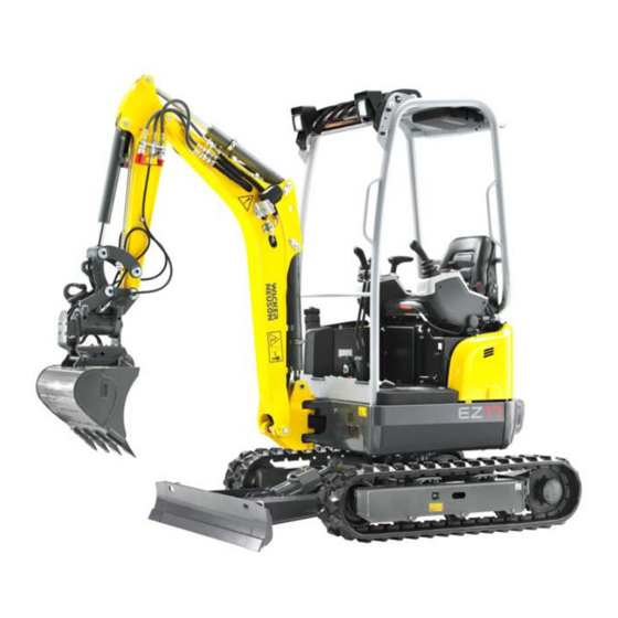
Introduction Introduction 3 Introduction Machine overview Fig. 2 Posi- Posi- Designation Designation tion tion Working light on boom Tie-down point for tying down the machine Roof lights (option) Stabilizer blade Lifting eye Travel gear Rotating beacon (option) Handhold Engine cover Extra weight (option) Fuel tank filler inlet Towing eye... -
Page 38: Brief Description Of Machine
Trade name E13-01 EZ17 Brief description of machine The Wacker Neuson model EZ17 track excavator is a self-propelled work machine. It is a powerful, highly flexible, efficient and environmentally friendly construction machine. They are mainly used for loosening and moving earth, for example for digging and filling up construction pits. - Page 39 Introduction 3 Canopy The canopy has been specially designed for protection in case of an accident. • ROPS/TOPS tested canopy. • Protective FOPS structure level I (option); Protective structure against falling objects. • Shatter protection (option); Protective structure against frontal flying fragments.
-
Page 40: Information And Regulations On Use
9-14. - Every other use is regarded as not designated for the use of the machine. Wacker Neuson will not be liable for damage resulting from use other than mentioned above. The user/operating company alone will bear the risk. -
Page 41: Labels
Introduction 3 Labels WARNING Injury hazard due to missing or damaged labels! A missing, incomplete or poor indication of danger can cause serious injury or death. ► Do not remove warning and information labels. ► Immediately replace damaged warning and information labels. Information Type, quantity, and position of the labels depend on options, country and machine. - Page 42 3 Introduction Type labels The vehicle nameplate is located at the front left on the revolving superstructure. Fig. 4 Serial number The serial number is stamped on the machine chassis. It is also located on the type label. Fig. 5 (symbolic representation) The machine type label contains the following information: Description of attachment HYDRAULIC EXCAVATOR...
- Page 43 Introduction 3 17-digit serial number (from 2012) For easier machine identification, Wacker Neuson introduced a 17-digit serial number for compact equipment in 2012 (for example for excavators). This serial number includes additional data, for example, the manufacturer code and the production site.
- Page 44 3 Introduction Canopy type label The type label is located behind the seat on the chassis. Fig. 7 FOPS screen type label The type label is located at the front on the lower side of the frame. Fig. 8 BA EZ17 en* 1.1 * ez17e300.fm...
- Page 45 Introduction 3 Warning labels BA EZ17 en* 1.1 * ez17e300.fm...
- Page 46 3 Introduction Meaning Crushing hazard. All persons must stay clear of a raised load or of the danger zone. Position On the left and right side on the lifting arm. Fig. 10 Meaning Injury hazard due to grease escaping under pressure. Read the Operator’s Manual before working with the track tensioner.
- Page 47 Introduction 3 Meaning Accumulator is under high pressure. Maintenance or repair work may be performed only by a Wacker Neuson service center. Position Left underneath the foot mat Fig. 16 Meaning Pressure relief in hydraulic system. Read and understand the Operator’s Manual.
- Page 48 3 Introduction Meaning Read the Operator’s Manual before starting the machine. Fasten your seat belt. Lower the boom and the stabilizer blade to the ground. Remove the starting key and carry it with you. Raise the control lever base. Crush Hazard Possible serious machine damage Keep a safe distance from the cabin.
- Page 49 Introduction 3 Meaning Read the Operator’s Manual before starting the machine. Remove the starting key and carry it with you. Injury hazard due to rotating parts. • Open the engine cover only at engine standstill. Burn hazard due to hot surfaces. •...
- Page 50 3 Introduction Labels 3-14 BA EZ17 en* 1.1 * ez17e300.fm...
- Page 51 Introduction 3 Meaning Only refuel with diesel fuel with a sulfur content of < 15 mg/kg (= 0.0015 %). Position Next to the fuel tank filler inlet Fig. 25 Meaning (option) The reservoir contains biodegradable hydraulic oil. This label is notched on the side depending on the biodegradable hydraulic oil used.
- Page 52 3 Introduction Meaning Lubrication interval Position On the right side of the chassis. Fig. 30 Meaning Hydraulic functions active or locked Position On control lever base Fig. 31 Meaning Fuses and relays Position On the inside of the battery cover Fig.
- Page 53 Introduction 3 Meaning (option) Check before starting the machine the operating pattern that has been chosen. Wiring diagram Controls ISO controls Fig. 34 SAE controls Position At the left under the operator seat. Meaning (option) Operating procedures differing from the ISO controls if the SAE controls are set.
- Page 54 3 Introduction Meaning Maintenance intervals Position On the roof window Fig. 38 Meaning Hydraulic Easy Lock quickhitch Position On the headliner Fig. 39 3-18 BA EZ17 en* 1.1 * ez17e300.fm...
-
Page 55: Putting Into Operation
Putting into operation Putting into operation 4 Putting into operation Cabin/control stand Safety instructions regarding entry and exit CAUTION Falling hazard when entering or exiting! Entering or exiting incorrectly can cause injury. ► Keep the mandatory climbing aids A clean and use only them for entering and exiting. - Page 56 4 Putting into operation Rear tarpaulin (option) Installing/removing 1. Stop and park the machine. Stop the engine. See “Preparing lubrication”. 2. Roll up the rear tarpaulin and secure it with both straps A. Fig. 41 3. Push the rear tarpaulin into the frame or pull it out of the rail under it. Fig.
- Page 57 Putting into operation 4 Unrolling/rolling up the rear tarpaulin 1. Stop and park the machine. Stop the engine. See “Preparing lubrication”. 2. Unhitch both straps A and unroll the rear tarpaulin. Fig. 44 3. Fasten the belt C to the six points on the outside of the canopy. Fig.
- Page 58 4 Putting into operation Seat adjustment WARNING Accident hazard when adjusting the operator seat during machine operation! Adjusting the operator seat during machine operation can cause serious injury or death. ► Adjust the operator seat before putting the machine into operation. ►...
- Page 59 Putting into operation 4 Horizontal adjustment 1. Sit down on the operator seat. 2. Pull lever B upward and lock seat into place in the required position. Fig. 48 Backrest adjustment Sit down on the operator seat. Backrest inclination to the rear: •...
- Page 60 ► Have a damaged seat belt and buckle immediately replaced by an authorized service center. ► Have the seat belt immediately replaced after every accident and the load-bearing capacity of the fastening points and seat fixtures checked by a Wacker Neuson service center. BA EZ17 en* 1.1 * ez17i400.fm...
- Page 61 Putting into operation 4 Fastening the retracting lap belt 1. Insert buckle latch A into seat belt buckle B until it engages. Fig. 50 Unfastening the retracting seat belt 1. Press the red push button D on seat belt buckle B until the buckle latch comes out.
- Page 62 4 Putting into operation Adjusting the mirrors (option) WARNING Injury hazard to persons in the danger zone! Persons in the danger zone are possibly not seen when reversing the machine and may be injured. This can cause accidents with serious injuries or death.
- Page 63 • Ensure visibility of the rear right edge of the machine in the mirror on the right. Information Wacker Neuson recommends adjusting the mirrors with two persons. Fig. 52 Information Do not make any modifications that impair visibility. Otherwise the machine does not meet the requirements for conformity and registration.
- Page 64 Fig. 53 Fire extinguisher A fire extinguisher is not available from Wacker Neuson. Contact a Wacker Neuson service center for the installation of a fire extinguisher (DIN-EN 3). Information Ensure the firm and safe installation of the fire extinguisher. Check the fire extinguisher at regular intervals, also ensure that it is safely installed.
- Page 65 ► Replace the complete protective structure if it is damaged, deformed or cracked. ► Contact a Wacker Neuson service center in case of doubt. ► Retrofit, assembly and repair work may only be performed by a Wacker Neuson service center.
- Page 66 4 Putting into operation Protective FOPS structure/small screen – category I (option) DANGER Crushing hazard due to falling objects! Falling objects cause serious injuries or death. ► Install a protective FOPS structure for machine operation in areas with danger of falling objects. Information The protective FOPS structure corresponds to category I according to ISO 3449:1992...
- Page 67 Putting into operation 4 6. Install the lights in positions C (option). Fig. 57 7. Install the mirror on the left and right in positions D (option). Fig. 58 4-13 BA EZ17 en* 1.1 * ez17i400.fm...
- Page 68 4 Putting into operation Shatter protection (option) DANGER Danger of piercing/penetration by objects from the front! Work involving the danger of piercing/penetrating objects from the front can cause accidents with serious injury or death. ► To operate the vehicle, shatter protection must be installed if an attachment (a breaker, for example) causes fragments to fly around.
- Page 69 Work range height A: 120 cm (47 in), B: 50 cm (20 in) 45° Fig. 59 (symbolic representation) Figures 59 and 60 refer to work with a Wacker Neuson hydraulic hammer. Working with another tool can result in a different work range. Fig. 60 (symbolic representation) Assembly 1.
- Page 70 4 Putting into operation Power outlet The machine is equpped with a 12 V socket on the right. Fig. 63 4-16 BA EZ17 en* 1.1 * ez17i400.fm...
-
Page 71: Overview Of Control Elements
Putting into operation 4 Overview of control elements This chapter describes the controls, and contains information on the function and handling of the indicator lights and controls on the machine. The pages stated in the table refer to the description of the controls. 4-17 BA EZ17 en* 1.1 * ez17i400.fm... - Page 72 4 Putting into operation Canopy Fig. 64 Standard controls Fig. 64 Proportional controls 4-18 BA EZ17 en* 1.1 * ez17i400.fm...
- Page 73 Putting into operation 4 Designation See page 5-26 Boom swivel pedal Drive levers 5-26 Auxiliary hydraulics pedal 5-38 Foot-operated push button for hydraulic quickhitch (option) Horn 5-12 Control levers 5-25, 5-26 Changeover for hammer/auxiliary hydraulics operation Pressure relief of hydraulic oil tank Travel speed changeover 5-16 10 Stabilizer-blade lever...
- Page 74 4 Putting into operation Display element and switches Switch panel on control lever base on the left Fig. 65 4-20 BA EZ17 en* 1.1 * ez17i400.fm...
- Page 75 29 Engine oil pressure 4-22 30 Preheating 4-22 31 Safe load indicator light 4-23 32 Coolant temperature 33 For Wacker Neuson service center 4-23 34 Hour meter/maintenance meter 4-23 35 Hour meter/maintenance meter changeover 36 Not assigned 37 Not assigned...
-
Page 76: Indicator Lights And Warning Lights (Overview)
The indicator light (yellow) illuminates if the starting key is in position 2. The control lamp goes out after four seconds and the engine can be started. Contact a Wacker Neuson service center if the indicator light does not go out. Overload warning light The overload warning device (red) gives the operator visual (red) and acoustic warnings when the values from the stability table are exceeded. - Page 77 Putting into operation 4 Symbol Designation Coolant temperature The control lamp A lights up if the segments reach the red area. • Let the engine run at idling speed without any load. • Wait until the temperature drops and the indicator light goes out. •...
-
Page 78: Preparatory Work
4 Putting into operation Preparatory work Important information before putting the machine into operation Perform a visual check before starting work: - There must be no leaks. - There must be no damaged or loose parts. - Do not allow anyone to stay in the danger zone. Before putting the machine into operation, the operator must familiarize himself with the position of the controls and instruments. - Page 79 The checklists below assist you in checking and monitoring the machine before, during, and after operation. Wacker Neuson does not claim those lists to be exhaustive. If the answer to one of the questions is No, first rectify the cause of the fault (or have it rectified) before starting work.
- Page 80 4 Putting into operation Operation checklist Check/observe the following points before beginning operation or after starting the engine: No. Question Page Are there any persons or objects in the danger zone of the 5-54 machine? 5-55 All indicator lights gone out? 4-22 Coolant temperature of engine in normal range? 4-23...
- Page 81 Putting into operation 4 Putting into operation for the first time and running-in period Before putting the machine into operation for the first time, check whether the equipment supplied with the machine is complete. • Check the fluid levels according to chapter “Maintenance”. Each machine is correctly adjusted and checked before it is delivered.
-
Page 82: Starting And Stopping The Engine
4 Putting into operation Starting and stopping the engine Preparatory work WARNING Accident hazard due to unintentional operation of the machine! Unintentional operation can cause serious injury or death. ► Only operate the machine from the seat with the seat belt fastened. Set the throttle to the middle position if the engine is cold. - Page 83 ➥ Work may be performed with the machine. 8. The selected elements move: ➥ Stop operation immediately. Contact a Wacker Neuson service center and have the malfunction rectified. NOTICE Possible damage if the engine is started again immediately after stopping ►...
- Page 84 2. Turn the starting key to position 1. 3. All control lamps light up for a few seconds. ➥ If a control lamp does not function, contact a Wacker Neuson service center. 4. Turn and hold the ignition key in position 2 until indicator light 30 (preheating) goes out.
- Page 85 Putting into operation 4 Starting aid WARNING Explosion hazard in case of incorrect handling of battery! Incorrect battery handling can cause serious injury or death. ► Wear protective equipment. ► Fire, open flames and smoking is prohibited ► Do not jump start the engine if the battery is malfunctioning or frozen, or if the acid level is too low.
- Page 86 4 Putting into operation NOTICE Possible damage due to wrong battery voltage. ► Only use batteries with the same voltage (12 V). NOTICE Possible damage to machine with empty battery due to voltage peaks. NOTICE Possible damage to battery jumper cables when placing them near rotating parts.
- Page 87 Putting into operation 4 Designations/symbols Meaning Machine with empty battery Vehicle with full battery Positive/machine X Positive/vehicle Y Negative/vehicle Y Negative/machine X Full battery Fig. 70 Dead battery 1. Move vehicle Y close to machine X so that the length of the battery jumper cables is sufficient.
- Page 88 4 Putting into operation Low-load operation NOTICE Possible damage to the engine due to low-load operation. ► Run the engine at idling speed or at high engine speed at over 20 % engine load. Possible consequences of low-load operation are: •...
- Page 89 Putting into operation 4 Battery master switch NOTICE Possible damage to the electronics due to improper actuation of the battery master switch! ► Do not operate the battery master switch with a running engine. ► Operate the battery isolator switch no sooner than two minutes after shutting off the engine.
- Page 90 4 Putting into operation Notes: 4-36 BA EZ17 en* 1.1 * ez17i400.fm...
-
Page 91: Operation
Operation Operation 5 Operation Steering system Movement Drive levers/accelerator pedals Steering to the left Steering to the right Rotation to the left Rotation to the right Accelerator actuation Manual throttle The engine speed can be variably set with the throttle lever A. Engine speed Position Idling speed... -
Page 92: Brakes
5 Operation Speed range selection The machine has two speed ranges that can be selected with the dozer blade lever. 1: Speed 1 2: Speed 2 (control lamp B appears in the display element) Information In speed 2, reduced tractive power jerky movements may occur when cornering due to the lower traction force. -
Page 93: Machine Travel
Operation 5 Machine travel Machine travel position Position the machine as shown. Position the boom at the center and raise it off the ground. • A = 20-30 cm (8-12 in) Fig. 75 Starting machine travel and stopping WARNING Accident hazard due to incorrect machine operation! The machine moves in the opposite direction if the upper carriage is rotated by 180°... - Page 94 5 Operation Operating temperature range Operate the machine only at ambient temperatures between −15 °C (5 °F) and +45 °C (+113 °F). Machine travel on slopes WARNING Crushing hazard due to tipping over of machine! A tipping machine can cause serious injury or death. ►...
- Page 95 Operation 5 Preparations for performing machine travel on slopes Always perform uphill or downhill machine travel in a straight line. When changing position, do not exceed a maximum gradient angle of 15° and a maximum lateral angle of inclination of 10°. <...
- Page 96 5 Operation Uphill machine operation • Raise the boom 20 – 30 cm (8 – 12 in) off the ground and position it straight ahead at the center of the machine. • Do not perform machine travel on slopes steeper than 15°. •...
-
Page 97: Differential Lock
Operation 5 Parking the machine WARNING Crushing hazard due to machine rolling away under its own weight after parking it! Serious injury or death can be caused by not securing the machine. ► Lower the boom and the stabilizer blade to the ground. ►... -
Page 98: Lights/Signalling System
5 Operation Lights/signalling system WARNING Accident hazard due to blinded motorists! Working lights can blind motorists. This can cause serious injury or death. ► Stop machine operation if motorists are blinded. ► Take up operation again only when sufficient illumination of the working area is ensured without blinding motorists. - Page 99 Operation 5 Horn Press touch control A on the right-hand control lever to actuate the horn. Fig. 84 Rotating beacon (option) The rotating beacon has a magnetic base and is attached to the cabin roof. The electric power supply has a 12 volt connection A. Information Wrap the power cable around the right A-column.
- Page 100 ► Despite the traveling signal the danger zone must also be monitored visually. ► If the travel signal does not sound, stop machine operation immediately and contact a Wacker Neuson service center. Follow the relevant national and regional regulations. 5-10...
-
Page 101: Wiper/Wash System
Operation 5 Wiper/wash system Not available. Heating, ventilation and air conditioning system Not available. 5-11 BA EZ17 en* 1.1 * ez17b500.fm... -
Page 102: Work Hydraulics
Operation 5 Operation Work hydraulics Overview of pedals and control levers (ISO control) Symbol Designation Symbol Designation Left track (forward) Right track (forward) Left track (reverse) Right track (reverse) Extend stick Swivel upper carriage to the right Retract stick Swivel upper carriage to the left Swivel boom to the right Swivel boom to the left Lower the boom... - Page 103 Operation 5 Overview of pedals and control levers (SAE control) Symbol Designation Symbol Designation Left track (forward) Right track (forward) Left track (reverse) Right track (reverse) Extend stick Swivel upper carriage to the right Retract stick Swivel upper carriage to the left Swivel boom to the right Swivel boom to the left Lower the boom...
- Page 104 5 Operation Rotating the upper carriage WARNING Crushing hazard due to rotating range of machine! Persons in the rotation range of the machine can be seriously injured or killed. ► Do not allow anyone to stay in the danger zone. NOTICE Possible damage to machine when working in the immediate vicinity of walls, parts of buildings or other obstacles.
- Page 105 ► Always secure the wing nut on the reversing valve. ► Do not operate the machine with a defective wing nut. Contact a Wacker Neuson service center. The reversing valve is located at the left under the operator’s seat. Wiring diagram...
- Page 106 5 Operation Dozer blade WARNING Crushing hazard due to unintentional actuation! Unintentional actuation can cause serious injury or death. ► Raise the control lever base. ► Lower the stabilizer blade to the ground after the work shift. ► Do not allow anyone to stay in the danger zone. NOTICE Lowering the stabilizer blade too deeply into the ground can create increased resistance.
- Page 107 Operation 5 Position Function The dozer blade is actuated. The telescopic travel gear is actuated. 1. Raise the control lever base. 2. Make sure that the lever A located to the left under the operator’s seat is in position 1. Fig.
- Page 108 5 Operation Changing the width of the stabilizer blade NOTICE Damage to machine when travelling through passages. ► The dozer blade and telescopic travel gear must have the same width. Reducing the width of the stabilizer blade 1. Raise the dozer blade a little. 2.
- Page 109 Operation 5 Telescopic travel gear WARNING Crushing hazard due to tipping over of machine! A tipping machine can cause serious injury or death. ► Only perform work with an extended telescopic travel gear. ► Performing machine travel with a retracted telescopic travel gear is only allowed for machine travel over very short distances through passages.
- Page 110 5 Operation Position Function The dozer blade is actuated. The telescopic travel gear is actuated. 1. Raise the control lever base. 2. Make sure that the lever A located to the left under the operator’s seat is in position 1. Fig.
- Page 111 Operation 5 8. Set the travel gear to the desired position. Telescopic travel Position gear Extend Push lever B forwards. Retract Pull lever B backward Fig. 100 9. Raise the control lever base. 10.Set lever A in position 1. Fig. 101 Information In order to ensure maximum stability during work: ►...
- Page 112 5 Operation Proportional controls (option) The proportional controls allow to continuously adjust the oil flow for the attachment. Actuate gate A to the left or right. Fig. 102 Set the desired flow rate with the rotary switch B. The proportional control is only available for control circuits AUX II and AUX III.
- Page 113 Operation 5 Hammer operation Only break in the prescribed work area with shatter protection. – see chapter “ Shatter protection (option)” on page 4-14 The machine is not certified for demolition work according to EN 474-5. A front guard cannot be attached. WARNING Danger of piercing/penetration by objects from the front! Work involving risk of piercing/penetrating by objects from the front can...
- Page 114 Work range height A: 120 cm (47 in), B: 50 cm (20 in) 45° Fig. 104 (symbolic representation) Figures 104 and 105 refer to work with a Wacker Neuson hydraulic hammer. Working with another tool can result in a different work range.
- Page 115 Operation 5 Switch over to breaker operation: Set the ball valve as shown. Hammer opera- Auxiliary tion (single-cir- hydraulics cuit function) (dual-circuit function) Fig. 106 Hammer operation Position Switch on Actuate the pedal A to the left Switch off Release the pedal A Fig.
- Page 116 5 Operation Additional control circuit – AUX I (option) Changeover to the dual-circuit function. The ball-type cock is located on Hammer Auxiliary the right in travelling direction in the machine. operation (sin- hydraulics gle-circuit (dual-circuit function) function) Fig. 109 Operating the additional control circuit Oil flow Position To the line on the left...
- Page 117 Operation 5 Additional control circuits AUX II (option) Set the desired flow rate with the rotary switch B. Fig. 112 Oil flow Position To the line on the left Press gate 22 to the left To the line on the right Press gate 22 to the right Fig.
- Page 118 5 Operation Powertilt – AUX III (option) WARNING Crushing hazard due to rotating movements of the Powertilt unit! Rotating the Powertilt unit can cause serious injury or death. ► Do not allow anyone to stay in the danger zone. Information For more information, see Easy Lock/Powertilt with Easy Lock Operator’s Manual.
- Page 119 Operation 5 Set the desired flow rate with the rotary switch B. Fig. 114 Actuating the Powertilt unit Fig. 115 Powertilt Position Rotation Rotation the left the right Rotation to the left Press gate 22 to the left Rotation to the right Press gate 22 to the right Fig.
- Page 120 5 Operation Lifting gear applications Lifting gear applications are procedures involving raising, transporting and lowering loads with the help of lifting and fastening gear. DANGER Crushing hazard due to tipping over of machine! The machine causes serious injury or death when it tips over. ►...
- Page 121 Operation 5 Safe load indicator The safe load indicator alerts the operator visually and acoustically if the load on the boom is too high. There are two versions: • Overload warning device basic (option) / advanced (option) Position basic advanced Boom Hose burst valve Hose burst valve...
- Page 122 5 Operation Functional check of safe load indicator Always perform a functional check of the safe load indicator before performing lifting gear applications. 1. Start the machine. 2. Perform machine travel on open terrain. 3. Secure the danger zone. 4. Stop the machine. 5.
- Page 123 Operation 5 Lehnhoff mechanical quickhitch system (optional) • The quick coupler system and the attachment support must be undamaged and clean. • Store the operator’s manual of the mechanical quick coupler system together with the operator’s manual of the machine. •...
- Page 124 5 Operation Picking up an attachment 1. Hook up the quick coupler system A in the attachment bolt B. 2. Slightly screw in the quick coupler system A, lift the shovel arm until the attachment is suspended about 30 cm (12 in) above the ground. 3.
- Page 125 Operation 5 9. Before starting any work and after every locking process, press the attachment to the ground and quickly move it back and forth over just over the ground a few times. ➥ The attachment may not detach from the quick coupler system in the process.
- Page 126 5 Operation Setting down an attachment 1. Screw in the attachment and position it at 5 – 10 cm (2 – 4 in) above the ground. 2. Shut off the engine and store the ignition switch key safely. Fig. 128 3.
- Page 127 Wacker Neuson is not liable for injuries or damage if at least one of the following items is not complied with: •...
- Page 128 5 Operation Hydraulic quickhitch system Easy Lock (option) • Attend specific training before putting into operation. Training must be given by authorized technical personnel and must be understood by the operator. • For safety reasons, the quickhitch must be operated with two control elements.
- Page 129 Operation 5 WARNING Danger of crushing due to incorrect operation of the hydraulic quickhitch system! For system-specific reasons, the quickhitch can also be operated with other hydraulic functions. This can cause serious injury or death. ► Operate the hydraulic quickhitch only with the function Raise stabilizer blade.
- Page 130 5 Operation ➥ Check pin F must be fully extended. ➥ The attachment engages. Fig. 134 7. Release the dozer blade lever J and foot-operated touch button E . ➥ The quickhitch closes. Fig. 135 ➥ Check pin F must be fully retracted. Fig.
- Page 131 Operation 5 9. Before starting any work and after every locking process, press the attachment to the ground and quickly move it back and forth over just over the ground a few times to check the secure locking. ➥ The attachment may not detach from the quick coupler system in the process.
- Page 132 5 Operation Manual HSWS bolt lock Depending on national provisions, the HSWS must also be manually locked according to the hydraulic locking process. The locking or unlocking is located to the left on the quick coupler system. Fig. 141 • Stop the engine and remove the starting key.
- Page 133 Operation 5 Setting down an attachment Manual HSWS bolt unlocking Depending on national provisions, the HSWS must also be manually unlocked according to the hydraulic unlocking process. The locking or unlocking is located to the left on the quick coupler system. Fig.
- Page 134 5 Operation 1. Move the attachment inward completely and position it at 5–10 cm (2–4 in) above the ground. 2. Unlock switch D and press it to position 1. ➥ The quickhitch is enabled and the buzzer sounds. Fig. 145 3.
- Page 135 Operation 5 5. Release the dozer blade lever J and foot-operated touch button E . ➥ The quickhitch closes. Fig. 149: Foot-operated push button and stabilizer-blade lever ➥ Check pin F must be fully retracted. Fig. 150: Retracted check pin 6.
- Page 136 5 Operation AUX V (option) Grab operation on the left: 1. Fit lever A onto the ball-type cock. 2. Set the ball-type cock to position B. ➥ The 90° notch indicates that grab operation is set. 3. Remove the lever after the changeover. Fig.
- Page 137 Operation 5 Connecting and disconnecting hydraulic couplings 1. Stop and park the machine. See “Preparing lubrication”. 2. Position the boom straight ahead at the center of the machine. 3. Lower the stabilizer blade to the ground. 4. Turn the starting key to position 1. 5.
- Page 138 5 Operation Load-retaining function (option) WARNING Injury hazard due to fluid escaping under pressure! Hydraulic oil escaping under pressure can penetrate the skin and cause serious injury or death. ► Do not allow anyone to stay in the danger zone. ►...
- Page 139 5. Raise the control lever base. 6. Remove the starting key and lock the cabin. 7. Secure the machine and the attachment. 8. Contact a Wacker Neuson service center and have the malfunction rectified. Environment Use a suitable container to collect fluids and lubricants as they flow out and dispose of them in an environmentally friendly manner.
-
Page 140: Attachments
5 Operation 5.10 Attachments Picking up WARNING Injury hazard due to fluid escaping under pressure! Hydraulic oil escaping under pressure can penetrate the skin and cause serious injury or death. ► Do not allow anyone to stay in the danger zone. ►... - Page 141 Operation 5 Setting down WARNING Crushing hazard when attachments are removed! If an attachment is not removed correctly, it can tip over and cause serious injury or death. ► Do not allow anyone to stay in the danger zone. ► Lower the attachment to level and firm ground ensuring stability. ►...
- Page 142 5 Operation Releasing the pressure in the work hydraulics 1. Stop the machine on firm, level, and horizontal ground. 2. Lower the attachment completely to the ground. 3. Lower the stabilizer blade to the ground. 4. Stop the engine. 5. Turn the starting key to position 1. 6.
- Page 143 Operation 5 Mount 1. Install a bucket only if it is positioned on level ground with the flat side facing downward. 2. Stop and park the machine. Stop the engine. See “Preparing lubrication”. 3. Apply grease to the pins and articulations before inserting them. 4.
-
Page 144: Work Operation
5 Operation 5.11 Work operation Danger zone • The danger zone is the area in which persons are in danger due to the movements of the machine, attachment or load. • The danger zone also includes the area that can be affected by falling material, equipment or by parts that are thrown out. - Page 145 Operation 5 Danger zone during lifting-gear applications In lifting gear applications the load must be stabilized by slingers (B) with the help of ropes (C). Slingers must remain out of the danger zone – see chapter “ Lifting gear applications” on page 5-30.
- Page 146 5 Operation Inadmissible work procedures Inadmissible operation can damage the machine or the attachment. Working with the swivel force Do not use the swivel force of the upper carriage to tear down walls or to create level surfaces. Never ram the attachment into the ground when swiveling the upper carriage.
- Page 147 Operation 5 Working with the falling force by lowering the machine Do not use the dead weight of the machine for work. Use the force of the hydraulic cylinders exclusively. Fig. 164 Fig. 165 Fully lowering the stabilizer blade Apply the full weight of the machine over the entire width of the stabilizer blade when using it for stabilization.
- Page 148 5 Operation General information regarding work operation Machine travel Performing machine travel over obstacles can put a heavy load on the undercarriage and cause damage. Avoid performing machine travel over obstacles if possible. If it cannot be avoided, lower the boom to ground level and travel over the obstacle at low speed.
- Page 149 Operation 5 Working with the bucket The following section describes work operations with the machine equipped with a backhoe bucket. The backhoe bucket is mainly used for earth-moving applications (digging, loosening, picking up and loading loose or solid material). Place the stabilizer blade on the side you want to dig. Bucket position when digging Perform long, level excavation movements with the stick and the bucket.
- Page 150 5 Operation Loading material Notes on loading site dumpers: - Position the site dumper so that its cabin is outside the danger zone of the excavator. - The loading platform of the truck is loaded by starting at the rear end. - Keep the swivel angle as small as possible.
- Page 151 ► The piston rod must not touch the stabilizer blade. Fig. 176 Hints for digging When planning and performing digging work, Wacker Neuson recommends that you observe the following points: • Exits from pits must be outside the digging line and as level as possible.
-
Page 152: Emergency Lowering
5 Operation 5.12 Emergency lowering DANGER Crushing hazard during boom lowering! Causes serious crushing or injury resulting in death. ► Do not allow anyone to stay in the danger zone. ► Stop machine operation immediately as soon as someone enters the danger zone. -
Page 153: Options
Operation 5 5.13 Options Immobiliser A = starting key (blue) For starting the machine. Scope of delivery includes 2 keys. B = master key (red) Fig. 177 Coding new starting keys 1. Insert master key B in the starter and turn it to position 1 for a maximum five seconds. - Page 154 5 Operation Face shovel operation Wacker Neuson backhoe buckets can also be used for shovel bucket operation. NOTICE The stick can be damaged if it is hit by the bucket base. ► Do not tilt out the bucket completely if it is used as a shovel bucket.
-
Page 155: Putting Out Of Operation/Back Into Operation
Operation 5 5.14 Putting out of operation/back into operation The specified measures refer to putting the machine out of operation and back into operation after more than 30 days. Putting out of operation temporarily Store the machine indoors if possible. If the machine has to be stored outdoors, place it on firm ground if possible (for example on concrete), and cover it with a watertight tarp to protect it against humidity. - Page 156 Putting back into operation Information If the machine was out of operation over a longer period of time without performing the specified steps, contact a Wacker Neuson service center before putting back into operation. 1. Remove anticorrosion agents from bare metal parts.
-
Page 157: Permanently Putting Out Of Operation
All fluids, lubricants, material, etc., used on the machine are subject to specific regulations. Dispose of different materials and consumables separately and in an environmentally friendly manner. Disposal may only be performed by a Wacker Neuson service center. Observe the corresponding national guidelines regarding disposal. Environment... - Page 158 5 Operation Notes: 5-68 BA EZ17 en* 1.1 * ez17b510.fm...
-
Page 159: Transportation
Transportation Transportation 6 Transportation Towing the machine WARNING Accident hazard due to incorrect towing! Incorrect towing can cause accidents and serious injury or death. ► Tow the machine away only from the immediate danger zone until it can be loaded. ►... - Page 160 6 Transportation – see chapter “ Towing” on page 2-11 2. Ensure that the machine can be towed safely. 3. Only use towing eye A . 4. Secure shackle B with the shackle pin and a lock pin. 5. Install towing equipment of appropriate size on the shackle. 6.
-
Page 161: Loading The Machine
Transportation 6 Loading the machine WARNING Accident hazard due to incorrect loading! Incorrect loading can cause accidents and serious injury or death. ► Do not allow anyone to stay in the danger zone. ► Bear in mind the transport weight on the machine’s type label. ►... - Page 162 6 Transportation 1. Observe chapter Transportation on page 2-13. 2. Secure the transport vehicle with chocks to prevent it from rolling. 3. Position the ramps at the smallest possible angle. Ensure that the grade does not exceed 15° (27 %). 4.
- Page 163 Transportation 6 Crane-lifting WARNING Accident hazard due to incorrect loading! Incorrect loading can cause accidents and serious injury or death. ► Do not allow anyone to stay in the danger zone. ► Bear in mind the transport weight on the machine’s type label. ►...
- Page 164 6 Transportation – see chapter “ Crane-lifting” on page 2-12 2. Fit an empty bucket and lock it safely. 3. Remove all dirt from the machine. 4. Park the vehicle on firm, level, and horizontal ground. 5. Tilt in bucket. 6.
-
Page 165: Transporting The Machine
Transportation 6 Transporting the machine Revolving superstructure lock NOTICE Possible serious machine damage. ► Do not rotate the locked revolving superstructure. The revolving superstructure lock locks the revolving superstructure during transport. Unlocking the upper carriage • Align the upper carriage with the travel gear. •... - Page 166 6 Transportation 1. The driver of the transport vehicle must observe the following before departure: - Permitted overall height, width and weight of the transport vehicle including the excavator. - The legal regulations of the countries where transport is to take place.
-
Page 167: Maintenance
Repair or replacement of safety-relevant parts may be performed only by a Wacker Neuson service center. Use only original spare parts for repairs. Wacker Neuson shall not be liable for damage to the machine or personal injury caused by failure to observe the specific information and descriptions. - Page 168 7 Maintenance Maintenance label Some maintenance work may only be performed by a Wacker Neuson service center (see maintenance schedule). Fig. 189 BA EZ17 en* 1.1 * ez17w700.fm...
- Page 169 Maintenance 7 Explanation of symbols on the maintenance label Symbol Assembly Explanation General Visual check General Visual check of machine (walk-around) General Lubrication points General Clean the radiator fins and the water separator fuel system Replace the fuel filter Radiator Check the coolant Radiator Draining coolant...
- Page 170 7 Maintenance Maintenance overview Maintenance plan Daily maintenance (user) Inspection work (Check the following fluids and lubricants, check the oil levels after a test run and add oil if nec- Page essary) 7-33, 7-35, Check the fluids and lubricants (engine oil, engine coolant, hydraulic oil) 7-40 Check the radiator and hydraulic oil cooler for dirt, clean them if necessary 7-36...
- Page 171 Rinse the system to remove dirt. Repeat the procedure in the opposite flow direction. Information Check the antifreeze at temperatures below 4 °C (39 °F). Only once after the first 50 operating hours (Wacker Neuson service center) Engine oil replacement Engine oil filter replacement...
- Page 172 Other maintenance intervals (Wacker Neuson service center): • Every 250 hours of operation or semi-annually • Every 500 operating hours or annually For additional details contact a Wacker Neuson service center. BA EZ17 en* 1.1 * ez17w700.fm...
- Page 173 Maintenance 7 Preparing lubrication 1. Stop the machine on firm, level, and horizontal ground. 2. Position the boom straight ahead at the center of the machine. 3. Lower the boom and the stabilizer legs to the ground. 4. Stop the engine. 5.
- Page 174 7 Maintenance Lubrication plan Fig. 191 Shown with Powertilt and hydraulic Easy Lock quickhitch (option) BA EZ17 en* 1.1 * ez17w700.fm...
- Page 175 Maintenance 7 Position Lubrication point Interval Quantity Boom Daily Stick cylinder Daily Bucket cylinder Daily Boom cylinder Daily Joint rod Daily Bucket pin Daily Shovel arm Daily Swiveling console Daily Stabilizer blade Every week Ball bearing race Every week Swiveling cylinder Daily Control lever base Every week...
- Page 176 7 Maintenance Live ring (ball bearing) DANGER Danger of crushing when lubricating the ball bearing race! Serious crushing danger causing death or serious injury! ► Park the machine as shown in Fig. 190. ► Do not rotate the upper carriage. 1.
- Page 177 Maintenance 7 Control lever base CAUTION Crushing hazard in the area of the moving parts of the control lever base. There is a risk of injury in the area of the moving parts. ► Stay clear (extremities, clothing) of the moving parts. 1.
-
Page 178: Engine/Vehicle Fluids
7 Maintenance Engine/vehicle fluids Season/temper- Application Fluid/lubricant Specification Capacities ature ASTM D975-94: 1D, 2D (USA) EN 590 (EU) ISO 8217 DMX (Inter- national) Diesel fuel 22 liters BS 2869-A1, A2 (GB) (5.8 gal) JIS K2204 (Japan) KSM-2610 (Korea) GB252 (China) Engine Year-round EN 14214... - Page 179 • Always have the condensation water in the hydraulic oil reservoir drained by a Wacker Neuson service center before the cold season. The water content may not exceed 0.1 % by weight. •...
- Page 180 7 Maintenance Engine oil types Ambient temperature Viscosity grade (SAE) min. °C min. °F max. °C max. °F 10W40 15W40 7-14 BA EZ17 en* 1.1 * ez17w700.fm...
-
Page 181: Maintenance Accesses
Maintenance 7 Maintenance accesses WARNING Injury hazard due to rotating parts! Rotating parts can cause serious injury or death. ► Open the engine cover only at engine standstill. ► Raise the operator seat only at engine standstill. CAUTION Burn hazard due to hot surfaces! Can cause serious burns. - Page 182 7 Maintenance Opening the engine cover 1. Stop and park the machine. Stop the engine. See “Preparing lubrication”. 2. Turn the starting key in lock A anticlockwise. 3. Press lock A and open the engine hood. Fig. 195 4. Make rod B engage in the lock. Fig.
- Page 183 Maintenance 7 Cover on the right Opening: 1. Stop and park the machine. Stop the engine. See “Preparing lubrication”. 2. Unscrew screws A. 3. Unhitch straps B and remove the side cover. Closing: Lock in the reverse order. Fig. 198 Cover on the left Opening: 1.
- Page 184 7 Maintenance Raising the operator seat 1. Stop and park the machine. Stop the engine. See “Preparing lubrication”. 2. Open the engine cover. 3. Pull out and hold lock A, and raise the operator seat. ➥ The operator's seat is unlocked. Fig.
- Page 185 Maintenance 7 Removing/installing the canopy It is possible to remove the canopy while going through a short passage. DANGER Accident hazard during machine travel without canopy! Serious crushing hazard causing death or serious injury. ► Do not fasten the seat belt in order to be able to leave the machine immediately in an emergency.
- Page 186 7 Maintenance 6. Remove the electric connector B if it is installed on the machine. The connector is located on the left behind the operator seat. Fig. 206 7. Install the lifting gear at the points provided for lifting the machine. The mandatory length L is a minimum 1300 mm (51 in).
- Page 187 Maintenance 7 NOTICE Damage to surface due to centering D on lower side. ► Raise the canopy sufficiently as you remove it. 10.Raise the canopy from the anchoring. Fig. 209 11.Swivel the revolving superstructure about 10° to the right to improve access to screws E.
- Page 188 7 Maintenance 2. Raise the canopy a little on either side, and press it into the anchoring. 3. Tighten screws C and D to 110 Nm (81 ft.lbs.). . The washers and securing elements can be used again. ➥ Raise the operator seat to improve access if necessary. Fig.
-
Page 189: Cleaning And Maintenance
Maintenance 7 Cleaning and maintenance WARNING Injury hazard due to rotating parts! Rotating parts can cause serious injury or death. ► Open the engine cover only at engine standstill. WARNING Burn hazard due to hot surfaces! Hot surfaces can cause serious burns or death. ►... - Page 190 7 Maintenance Cleaning the machine is divided into three separate areas: • Inside the cabin • Exterior of the machine • Engine compartment Washing solvents • Ensure sufficient room ventilation. • Wear suitable protective clothing. • Do not use flammable liquids, such as gasoline or diesel. Compressed air •...
- Page 191 2. See “Preparing lubrication”. 3. Check the machine for salt deposits or corrosion. Have corrosion removed by a Wacker Neuson service center. 4. Clean the machine with a high-pressure cleaner. Clean the machine ensuring that there are no salt deposits in places that are difficult to access.
-
Page 192: Lubrication Work
7 Maintenance Lubrication work – see chapter “ Preparing lubrication” on page 7-7 Fuel system Important information regarding the fuel system Information In order to prevent the formation of condensation water, fill up the fuel tank nearly completely at the end of each working day. Information Do not run the fuel tank completely dry. - Page 193 Maintenance 7 Refueling WARNING Explosion hazard due to flammable fuel/air mixtures! Fuels develop explosive and flammable mixtures with air that can cause serious burns or death. ► Fire, open flames and smoking is prohibited. ► Open tank lock carefully to release the pressure in the fuel tank. ►...
- Page 194 7 Maintenance Refueling Filler inlet A of the fuel tank is located on the right in travel direction. 1. Stop and park the machine. Stop the engine. See “Preparing lubrication”. 2. Unlock the lock on filler inlet A with the starting key. 3.
- Page 195 Maintenance 7 Checking the water separator Water separator Empty the water separator if the red indicator ring A rises to position B. Fig. 214 Emptying the water separator Information The fuel system can be bled automatically even if the engine is at operating temperature –...
- Page 196 7 Maintenance Checking the fuel filter Fuel filter Empty the fuel filter if the fuel/water mixture reaches position A. Fig. 216 Emptying the fuel filter Information The fuel system can be bled automatically even if the engine is at operating temperature –...
- Page 197 3. Remove the starting key and carry it with you. 4. Bleed the fuel system again as described above. 5. Check for leaks after starting the engine. 6. Have a Wacker Neuson service center perform a check if necessary. 7-31 BA EZ17 en* 1.1 * ez17w700.fm...
-
Page 198: Engine Lubrication System
NOTICE Damage due to wrong engine oil. ► Use engine oil according to the engine/vehicle fluids list. ► Have the oil changed only by a Wacker Neuson service center. NOTICE Damage due to adding engine oil too quickly. ► Add the engine oil slowly so it can go down without entering the intake system. - Page 199 Maintenance 7 Checking the engine oil level 1. Stop and park the machine. Stop the engine. See “Preparing lubrication”. 2. Open the engine cover. 3. Wipe the area around oil-level dipstick with a lint-free cloth. 4. Pull out oil-level dipstick A and wipe it with a lint-free cloth. 5.
-
Page 200: Cooling System
7 Maintenance Cooling system Important information regarding the cooling system The radiators are located on the right in the engine compartment. WARNING Poisoning hazard due to hazardous substances! Contact with hazardous substances can cause serious injury or death. ► Wear protective equipment. ►... - Page 201 Maintenance 7 Checking the coolant level 1. Stop and park the machine. Stop the engine. See “Preparing lubrication”. FULL 2. Check the coolant level on the sight glass. 3. If the coolant level is below the FULL mark: ➥ Add coolant. Information Check the coolant level once a day before starting the engine.
- Page 202 7 Maintenance Cleaning the radiator CAUTION Burn hazard due to hot surfaces! Hot radiators can cause burns. ► Stop the engine and let it cool down. ► Wear protective equipment. NOTICE Damage to diesel engine and hydraulic system due to dirt on the radiator. ►...
-
Page 203: Air Filter
Maintenance Maintenance 7 7.10 Air filter Important information regarding the air filter • The air filter is composed of an interior and exterior filter. • Store the air filter in its original packaging and dry. • Check air filter, air filter attachments and air intake hoses for damage, and immediately repair or replace if necessary. -
Page 204: V-Belt
2. Remove the starting key and carry it with you. 3. Check and if necessary clean ventilation grill A. Fig. 225 7.11 V-belt V-belt tension may be checked and the V-belt retensioned only by a Wacker Neuson service center. 7-38 BA EZ17 en* 1.1 * ez17w710.fm... -
Page 205: Hydraulic System
► Malfunctioning or leaking threaded fittings, hose connections and pressure lines must be immediately repaired by a Wacker Neuson service center. Search for hydraulic leaks with a piece of cardboard. ► Always consult a doctor immediately, even if the wound seems insignificant. - Page 206 ► If the hydraulic oil in the sight glass is cloudy, this indicates that water or air has penetrated the hydraulic system. Contact a Wacker Neuson service center. ► Contact a Wacker Neuson service center if the filter of the hydraulic system is dirty. Checking the hydraulic oil level 1.
- Page 207 Maintenance 7 2. Remove lever C. 3. Remove screws D. 4. Remove the cover. Fig. 229 5. Open filler plug E slowly. 6. Add hydraulic oil up to the corresponding mark. 7. Check the hydraulic oil level on sight glass A. 8.
- Page 208 ► Have hydraulic hoses replaced every 6 years from the date of manufacture, even if they do not seem to be damaged. In this respect, Wacker Neuson recommends that you observe all the relevant safety regulations for hydraulic lines, as well as the safety regulations regarding accident prevention and occupational medicine in your country.
-
Page 209: Electrical System
• Light bulbs and fuses may be replaced by the operator. Alternator • Contact a Wacker Neuson service center if the alternator charge indicator light is malfunctioning. WARNING Injury hazard due to malfunctioning batteries! Batteries give off explosive gases that can cause deflagrations if ignited. -
Page 210: Heating, Ventilation And Air Conditioning System
Not available. 7.15 Washer system Not available. 7.16 Axles/travelling drive Have maintenance performed only by a Wacker Neuson service center. 7.17 Braking system Have maintenance performed only by a Wacker Neuson service center. 7-44 BA EZ17 en* 1.1 * ez17w710.fm... -
Page 211: Tracks
Maintenance 7 7.18 Tracks Checking track tension WARNING Crushing hazard during work under the machine! Working under the tracks can cause serious injury or death. ► Do not allow anyone to stay in the danger zone. 1. Park the vehicle on firm, level, and horizontal ground. 2. - Page 212 ► Open the lubricating valve only very carefully and do not unscrew it more than one revolution. ► Wear protective equipment. ► Contact a Wacker Neuson service center if you are unable to reduce the track tension. NOTICE Possible damage to cylinders and tracks due to overtightening.
- Page 213 9. Check the track tension again. ➥ If it is not correct: 10.Repeat steps 2 – 9. Contact a Wacker Neuson service center if track tension still is too low after pumping in more grease. Reducing tension 1. Place a suitable container underneath to collect the grease.
-
Page 214: Maintenance And Care Of Attachments
Have load hooks (Powertilt, Powertilt for Easylock) with inadmissible wear (for example beyond the tolerance), damage, deformations, surface cracks and corrosion immediately replaced by a Wacker Neuson service center. The nominal size must not be worn more than 10 % (max. tolerance). -
Page 215: Exhaust Gas Treatment
Maintenance 7 7.21 Exhaust gas treatment Not available 7.22 Machine preservation Machines are partly preserved at the factory (for example in the engine compartment). Operation in an aggressive environment (for example salt deposits) is prohibited. 7-49 BA EZ17 en* 1.1 * ez17w710.fm... - Page 216 7 Maintenance Notes: 7-50 BA EZ17 en* 1.1 * ez17w710.fm...
-
Page 217: Malfunctions
Malfunctions Malfunctions 8 Malfunctions Information Contact a Wacker Neuson service center in case of malfunctions or signs that are not listed in the following tables or that cannot be rectified with specified measures. Diesel engine malfunctions Malfunction/sign Possible cause Remedy... -
Page 218: Malfunctions Of The Travelling Drive
8 Malfunctions Malfunctions of the travelling drive Malfunction/sign Possible cause Remedy Wrong track tension Tighten tracks correctly 7-46 Machine does not stay on track, Foreign bodies (stones, for Remove foreign bodies machine pulls to the right or left example) stuck in tracks Uneven wear of tracks Contact a service center Malfunctions of the hydraulic system... -
Page 219: Disorders Of The Electrical System
Preheating indicator light (yellow) starter Have the error repaired by a remains illuminated when the engine Malfunctioning dis- Wacker Neuson service runs play element center Indicator light for engine oil pressure Pressure drop in (red) illuminates and the buzzer... - Page 220 8 Malfunctions Notes: BA EZ17 en* 1.1 * ez17b800.fm...
-
Page 221: Technical Data
Technical data Technical data 9 Technical data Models and trade names – see chapter “ Overview of models and trade name” on page 3-2 Engine Engine EZ17 Product Yanmar Type 3TNV76-SNSE12 Design Water-cooled 3-cylinder diesel engine Intake system Naturally aspirated engine fuel injection system Indirect Engine management... - Page 222 9 Technical data Engine EZ17 Product Yanmar diesel engine Type 3TNV80F-SSNS1 Design Water-cooled 3-cylinder diesel engine Intake system Naturally aspirated engine fuel injection system Indirect Engine management Mechanical Displacement 1266 cm (77.3 in Nominal bore and 80 x 84 mm (3.2 x 3.3 in) stroke 12.8 kW at 2200 rpm Power...
-
Page 223: Traveling Drive/Axles
Technical data 9 Traveling drive/axles EZ17 Travelling drive Axial piston motor Brake See drive lever Tracks Ground pres- Ground clear- Width Type sure ance mm (in) kg/cm (lbs/in mm (in) Rubber 230 (9) 0,28 (4) 156 (6) Steel 230 (9) 0,3 (4.3) 156 (6) Steering system... -
Page 224: Electrical System
► Do not repair or bypass fuses. ► If a replaced fuse is blown again directly, do not put the machine into operation and contact a Wacker Neuson service center. NOTICE Explosion hazard in case of incorrect handling of fuses. - Page 225 Technical data 9 Fuses The fuses and relay are located behind the battery cover, under the operator's seat. Remove the screw A and remove the battery cover. Fig. 238 F7 F8 Rated current Fuses EZ17 50 A Main fuse Main fuse, air-pressure sensor/per- 50 A formance adaptation (Yanmar 3TNV80F-SSNS1)
- Page 226 9 Technical data Bulbs EZ17 Working lights/roof lights Halogen lamp 12 V 55 W H3 Rotating beacon Halogen lamp 12 V-55 W H1 Powertilt (option) EZ17 Model size Required oil flow 2-4 l/min (0.5-1 gal/min) Swiveling range 180° Weight 35 kg (77.2 lbs) Drive torque –...
-
Page 227: Tightening Torques
Technical data 9 Tightening torques General tightening torques Property class 10.9 12.9 10.9 Screws according to DIN 912, DIN 931, DIN 933, etc. Screws according to DIN 7984 Screw dimen- sions Nm (ft.lbs.) Nm (ft.lbs.) Nm (ft.lbs.) Nm (ft.lbs.) Nm (ft.lbs.) 5.5 (4) 8 (6) 10 (7) -
Page 228: Coolant
9 Technical data 9.10 Coolant Compound table Outside tempera- Distilled water Coolant ture Up to °C (°F) % by volume % by volume -37 (-34.6) Use the 1:1 concentration for warm outside temperatures, too, to ensure protection against corrosion, cavitation, and deposits. Do not mix the coolant with other coolants. -
Page 229: Vibration
Technical data 9 9.12 Vibration Vibration Effective acceleration value for the upper extremi- < Trigger value ties of the body (hand-arm vibration) < 2.5 m/s Effective acceleration value for the body (whole- < 0.5 m/s body vibration) Vibration values indicated in m/s². Directive 2002/44/EC of European Parliament and Council on minimum health and safety requirements regarding exposure of workers to risks arising from physical agents (vibration). - Page 230 9 Technical data It explains the values for vertical vibration under heavy operating conditions. Directives on reduction of vibration values in earth moving machines: • Perform correct adjustments and maintenance on the machine. • Avoid jerky movements during machine operation. •...
- Page 231 European Parliament and Council on minimum health and safety requirements regarding exposure of workers to risks arising from physical agents (vibration). Your Wacker Neuson dealer provides information on other machine functions reducing vibration and on safe operation. 9-11 BA EZ17 en* 1.1 * ez17t900.fm...
-
Page 232: Weight
Long stick 6 (13) Attachments – see chapter “ Technical data of attachments” on page 9-14 Full fuel tank 19 (42) The weight indications for options exclusively refer to Wacker Neuson original accessories. 9-12 BA EZ17 en* 1.1 * ez17t900.fm... - Page 233 Accident hazard due to unauthorized attachments! If unauthorized attachments are used, the machine can tip over, which can lead to serious injury or death. ► Only use attachments released by Wacker Neuson. NOTICE Machine can be damaged due to unreleased attachments.
- Page 234 9 Technical data Technical data of attachments EZ17 (without quickhitch system) Width Capacity Weight Bucket type mm (in) kg (lbs) Bucket 250 (10) 0,023 (0.81) 30 (66) Bucket 300 (12) 0.028 (0.99) 32 (71) Bucket 400 (16) 0.035 (1.2) 37 (82) Bucket 500 (20) 0.044 (1.6)
- Page 235 Technical data 9 Excavator forces According to ISO 6015 EZ17 Max. tearout force 9.1 kN (2,046 lbf) (short stick) Max. tearout force 8.1 kN (1,821 lbf) (long stick) Max. breakout force 18.7 kN (4,204 lbf) at bucket tooth 9-15 BA EZ17 en* 1.1 * ez17t900.fm...
-
Page 236: Lift Capacity/Load
9 Technical data 9.14 Lift capacity/load Safety instructions lift capacity tables Observe the values of the lift capacity tables in normal operation (for example excavating). Observe the values of the load diagrams in lifting gear applications. DANGER Crushing hazard due to tipping over of machine! The machine causes serious injury or death when it tips over. - Page 237 Technical data 9 Legend Designation Explanation Reach from live ring center Load hook height Admissible weight or mass value with boom in horizontal position With or without the stabilizer blade in travelling direction With or without the stabilizer blade, 90° to travel direction Lowered stabilizer blade Raised stabilizer blade Telescopic travel gear extended...
- Page 238 9 Technical data All table values are specified in kg (lbs), in horizontal position on firm and level ground without bucket or attachment (for example a breaker). The machine’s lift capacity is restricted by the settings of the pressure limiting valves, the hydraulic output and the hydraulic system’s stabilizing features.
- Page 239 Technical data 9 Lift capacity table EZ17 Lift capacity table EZ17 (short stick) 3.0 m (9'-10") 2.5 m (98 in) 2.0 m (79 in) 1.5 m (59 in) 2.5 m (98 in) (1,045) (666) (603) (1,034) (674) (611) 2.0 m (79 in) (1,032) (510)
- Page 240 9 Technical data Lift capacity table EZ17 with extra weight (short stick) 3.0 m (9'-10") 2.5 m (98 in) 2.0 m (79 in) 1.5 m (59 in) 2.5 m (98 in) (1,045) (719) (659) (1,034) (728) (668) 2.0 m (79 in) (1,032) (553) (502)
- Page 241 Technical data 9 Safety instructions load diagrams The values of the stability table (load diagram) apply to lifting gear applications. DANGER Crushing hazard due to tipping over of machine! The machine causes serious injury or death when it tips over. ►...
- Page 242 9 Technical data Legend Designation Explanation Reach from live ring center Load hook height in the respective range Authorized lift capacity with horizontal boom Stick short/long Authorized lift capacity applies to entire swiveling range of 360°. All table indications in kg (lbs) and horizontal position on firm and level ground without bucket or exchangeable attachment.
- Page 243 Technical data 9 Canopy, without extra weight Fig. 241 Canopy, with extra weight Fig. 242 9-23 BA EZ17 en* 1.1 * ez17t900.fm...
- Page 244 9 Technical data Dimensions Fig. 243 9-24 BA EZ17 en* 1.1 * ez17t900.fm...
- Page 245 Technical data 9 EZ17 Height 2360 mm (93 in) Canopy width 885 mm (35 in) Upper carriage width 980 mm (39 in) Width with retracted travel gear 990 mm (39 in) Width with extended travel gear 1300 mm (51 in) Transport length (short stick) 3585 mm (11'-9'') Transport length (long stick)
- Page 246 9 Technical data Notes: 9-26 BA EZ17 en* 1.1 * ez17t900.fm...
-
Page 247: Index Index
Index Index Index Index Cabin ..............4-1 Adding engine oil ..........7-33 Canopy ..............4-18 Adding hydraulic oil ..........7-40 Changing the width of the stabilizer blade .... 5-18 Additional control circuits ........5-27 Charge indicator light ........... 4-22 AUX I ............... 5-27 Check list AUX III (option) .......... - Page 248 Index 7-13 Hydraulic oil types ..........7-13 Easy Lock ............. 5-38 Hydraulic quickhitch ..........5-38 EC Declaration of Conformity ......EG-1 Picking up an attachment ........ 5-39 Electrical components ..........9-4 Setting down an attachment ......5-43 Electrical system ..........7-43 Hydraulic system ..........
- Page 249 Index Machine overview ..........3-1 Operation ..............5-1 Machine preservation ........... 7-49 Operation in water ..........5-58 Machine travel ............5-3 Operation near the sea ......... 5-58 Machine travel and stopping ......5-3 Operator seat ............4-4 Machine travel on slopes ........5-4 Backrest adjustment ..........
- Page 250 Index Safe load indicator ..........5-31 Seat belt ..............4-6 Serial number ............3-6 Shatter protection work range ............5-24 Stabilizer blade ............. 5-16 Starter ..............4-28 Start-up checklist ..........4-25 Steering system ............5-1 Switches ............... 4-20 Swiveling the boom ..........5-26 Technical data ............
- Page 251 Wacker Neuson Linz GmbH keep abreast of the latest technical developments and constantly improve their products. For this reason, we may from time to time need to make changes to figures and descriptions in this documentation that do not reflect products that have already been delivered and that will not be implemented on these machines.
- Page 252 Wacker Neuson Linz GmbH Flughafenstr. 7 A-4063 Hörsching Phone: +43 (0) 7221 63000 Fax: +43 (0) 7221 63000-2200 E-mail: office.linz@wackerneuson.com www.wackerneuson.com Order no. 1000299974 Language en...
Need help?
Do you have a question about the E13-01 and is the answer not in the manual?
Questions and answers