
Related Manuals for Wacker Neuson EZ17


Summary of Contents for Wacker Neuson EZ17
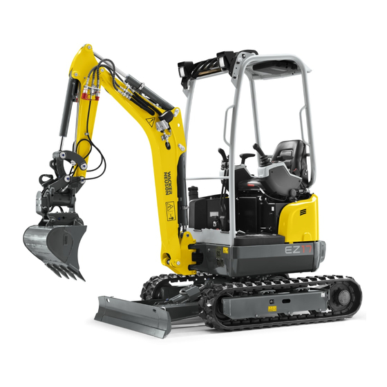
- Page 1 5200019151 0314 Track Excavator EZ17 OPERATOR’S MANUAL This Operator's Manual includes the AEM Safety Manual www.wackerneuson.com...
- Page 2 – without prior permission in writing from the manufacturer. No reproduction or translation of this publication, in whole or part, without the written consent of Wacker Neuson Linz GmbH.
- Page 3 5.14 Decommissioning and putting the machine back into operation............5-53 5.15 Final decommissioning of machine..................... 5-55 Transport 6.1 Towing the machine ..........................6-1 6.2 Loading the machine ..........................6-3 6.3 Transporting the machine ........................6-7 OM EZ17 us 1.0 * ez17us1_0IVZ.fm...
- Page 4 9.7 Work hydraulics ............................ 9-3 9.8 Electrical system........................... 9-4 9.9 Tightening torques ..........................9-6 9.10 Coolant ..............................9-7 9.11 Noise emissions............................ 9-7 9.12 Vibration..............................9-8 9.13 Weight..............................9-11 9.14 Payload/stability..........................9-12 Table of Contents Table of Contents............................S-1 OM EZ17 us 1.0 * ez17us1_0IVZ.fm...
- Page 5 DIN EN ISO 12100:2010, DIN EN 474-1:2006+A1:2009, DIN EN 474-5:2012, (except items 5.3.2.1 and 5.5) DIN EN ISO 3471:2010, DIN EN ISO 3744:2010, DIN EN ISO 3449:2008 Responsible for documentation Technical director Hörsching, Place, date EG-1 OM EZ17 us 1.0 * ez17konf.fm...
- Page 6 DIN EN ISO 12100:2010, DIN EN 474-1:2006+A1:2009, DIN EN 474-5:2012 (except item 5.3.2.1) DIN EN ISO 3471:2010, DIN EN ISO 3744:2010, DIN EN ISO 3449:2008 Hörsching, Responsible for documentation Technical director Place, date EG-2 OM EZ17 us 1.0 * ez17konf.fm...
- Page 7 Please contact your dealer if you require more information on the machine or the Operator’s Manual. The term “cab” used in this Operator’s Manual is used synonymously with the term “canopy” since this machine is only available with a canopy. OM EZ17 us 1.0 * ez17v100.fm...
- Page 8 Information Identifies an information that, when followed, provides for a more efficient and economical use of the machine. Environment Failure to observe the instructions identified by this symbol can cause damage to the environment. OM EZ17 us 1.0 * ez17v100.fm...
- Page 9 FGPS Front Guard Protective Structure Auxiliary hydraulic circuit Width Nominal width Stabilizer blade Stick HSWS Hydraulic Easy Lock quickhitch Service hours Pos. Position Fig. Figure e.g. for example approx. approximately max. maximum min. minimum OM EZ17 us 1.0 * ez17v100.fm...
- Page 10 (14.5 psi) 1 kg/cm² (14.22 lbs/in²) Force/output 1 kN (224.81 lbf) 1 kW (1.34 hp) 1 PS (0.986 hp) Torque 1 Nm (0.74 ft.lbs.) Speed 1 kph (0.62 mph) Acceleration 1 m/s² (3.28 ft/s²) OM EZ17 us 1.0 * ez17v100.fm...
- Page 11 • Wacker Neuson Linz GmbH shall not be liable for personal injury and/ or damage to property caused by failure to observe the safety instruc- tions and the Operator’s Manual, and by the negligence of the duty to...
- Page 12 Notes: OM EZ17 us 1.0 * ez17v100.fm...
- Page 13 Safety Information Safety Symbols Found in this Manual This is the safety alert symbol. It is used to alert you to potential personal hazards. • Obey all safety messages that follow this symbol. DANGER DANGER indicates a hazardous situation which, if not avoided, will result in death or serious injury.
- Page 14 5. Wacker Neuson shall not be liable for personal injury and/or damage to property caused by failure to observe the safety instructions on labels and in this Operator’s Manual, and by the negligence of the duty to exercise due care when: •...
- Page 15 Preparing to use the machine Conditions for use • The machine has been designed and built in accordance with state-of- the-art standards and recognized safety regulations. Nevertheless, its use can constitute a risk to the operator or to third parties, or cause damage to the machine and to other material property.
- Page 16 NEVER make any modifications, additions or conversions to the machine and its superstructures (for example, cab, etc.), or the machine’s attachments, without the approval of Wacker Neuson! Such modifications may affect safety and/or machine performance. This also applies to the installation and adjustment of safety devices and valves, as well as to welding work on load-bearing elements.
- Page 17 • The lifting gear must be checked regularly by a technician, at least once a year. • Replace damaged lifting gear immediately. • Fasten lifting gear and slings avoiding hazards (rotating parts, crushing or shearing) for the person securing the load. Furthermore, neither must the work equipment be affected by the lifting gear, nor must the functions of the lifting gear be affected by external influences (e.g.
- Page 18 Operator and Technician Qualifications and Basic Responsibili- ties Operator/machine owner responsibility • Only allow trained and experienced individuals to travel, maintain, or repair the machine. NEVER let unauthorized or underaged persons operate with the machine. • Clearly and unequivocally define the individual responsibilities of the operator and technician for operation, maintenance, and repair.
- Page 19 • Careful and prudent working is the best way to avoid accidents!Keep the machine clean. This reduces the risk of fire hazards (such as from combustible materials like rags), and reduces the risk of injury or operational accidents that can be caused by dirt build-up on the travel pedals or foot rests and steps.
- Page 20 Danger zone awareness • The danger zone is the area in which persons are jeopardized due to the movements of the machine, machine operation equipment, additional equipment, or material. • The danger zone also includes the area affected by falling material, equipment or construction debris.
- Page 21 • Check the machine before entering the cab to operate the machine for visible damage and defects. Report any changes, including changes in the machine’s function and response, to your supervisor immediately! • If the machine is functioning unpredictably, stop the machine immedi- ately, lock it, and report the malfunction to a qualified tecnician or supervisor.
- Page 22 • Machine travel with a raised load must be done very carefully on a level surface moving very slowly to avoid sudden motion that can cause swinging or oscillating motion of the load. • The person(s) attaching the load to the excavator shall approach only if the operator is in visual contact with them.
- Page 23 • Prior to fitting attachments to the stick (the mobile extension of the boom), secure the control lever of the hydraulic control unit against unintentional movement. Raise the left arm rest to avoid unintentional activation for the ISO/SAE operating mode. Avoid actuating the right hand control if the alternative control mode is selected.
- Page 24 • Observe the specific safety instructions in the Maintenance section of this Operator’s Manual. • Always keep a safe distance from all rotating and moving parts, for example, fan blades, V-belt drives, PTO shaft drives, fans, etc. • Before starting work on the machine, always ensure safe blocking/ support.
- Page 25 • Wear a safety harness when performing elevated maintenance on or with the machine. Keep all handles, steps, handrails, platforms, landings, and ladders free from dirt, snow and ice. • Always use specially designed or otherwise safety-oriented ladders and working platforms to perform overhead assembly work. NEVER use machine parts or attachments/superstructures as a climbing aid! •...
- Page 26 Tracks • Repair work on the tracks must be performed only by trained technical staff or by a Wacker Neuson service center. • Malfunctioning tracks reduce the machine's operational safety. Therefore, check the tracks regularly for cracks, cuts or other damage.
- Page 27 Hydraulics • Check all lines, hoses, and threaded couplers and fittings regularly for leaks and obvious damage. Repair any damage and leaks immedi- ately. Splashed oil can cause injury and fire! • In accordance with the Operator's Manual/instructions for the respective assembly, release the pressure in all system sections and pressure lines (hydraulic system) to be opened before perform any implementing/repair work!
- Page 28 2.11 Safety Guidelines while using Internal Combustion Engines WARNING Internal combustion engines present special hazards during operation and fueling. Failure to follow the warnings and safety guidelines could result in severe injury or death. ► Read and follow the warning instructions in the engine owner’s manual and the safety guidelines below.
- Page 29 Eye hook for tying down the machine Roof lights (option) Stabilizer blade Lifting eye Travel gear Rotating beacon (option) Handle Engine cover Extra weight (option) Fuel tank filler inlet Towing eye hook Exhaust pipe OM EZ17 us 1.0 * ez17e300.fm...
- Page 30 E13-01 EZ17 Brief description of the machine The machine model EZ17 is a self-propelled work machine. Get informed on and follow the legal regulations of your country. This machine is a versatile and powerful helper for moving earth, gravel and debris on construction sites and elsewhere. A wide range of attachments accounts for the numerous applications of the machine, among others hammer and grab applications.
- Page 31 Protection against heavy falling objects (FOPS) or heavy objects penetrating into the cab from the front (Front Guard), such as trees, pieces of rock, for machines that are used for clearance work, demolition work and forestry work, for example. OM EZ17 us 1.0 * ez17e300.fm...
- Page 32 3-5. - Every other use is regarded as not designated for the use of the machine. Wacker Neuson will not be liable for damage resulting from use other than mentioned above. The operator alone will bear the risk.
- Page 33 63 kg (139 lbs) 0.053 m (1.9 ft Ditch cleaning bucket 1000 mm (39 in) 66 kg (146 lbs) 0.082 m (2.9 ft EZ17 with hydraulic Easy Lock quickhitch Bucket type Width Capacity Weight Bucket 250 mm (10 in) 31 kg (68 lbs) 0.023 m...
- Page 34 EZ17 with hydraulic Easy Lock quickhitch Bucket type Width Capacity Weight Offset bucket 1000 mm (39 in) 93 kg (205 lbs) 0.063 m (2.2 ft EZ17 equipment Attachments Weight Hammer bracket HS 02 (NE 8/NE 12) 13.8 kg (66 lbs)
- Page 35 Maximum payload Front gross axle weight Zul. Achslast vorne/front GAWR/PNBE AV: rating Rear gross axle weight Zul. Achslast hinten/rear GAWR/PNBE AR: rating EWG Nr./CEE no.: EEC check number Baujahr/model year/année fabr.: Year of construction OM EZ17 us 1.0 * ez17e300.fm...
- Page 36 The type label is located on the valve cover (engine). Fig. 7 Hydraulic quickhitch The serial number is located on the type label. The type label is located on the hydraulic quickhitch fork. Fig. 8 OM EZ17 us 1.0 * ez17e300.fm...
- Page 37 The serial number of the hydraulic quickhitch is located on the type label. The type label is located on the hydraulic quickhitch fork. Fig. 9 FOPS type label The type label is located at the front on the lower side of the frame. Fig. 10 OM EZ17 us 1.0 * ez17e300.fm...
- Page 38 Warning labels Fig. 11 (symbolic representation) 3-10 OM EZ17 us 1.0 * ez17e300.fm...
- Page 39 Position A the rear of the seat. Fig. 16 Meaning Accumulator is under high pressure. Maintenance or repair work may only be performed by a Wacker Neuson service center. Position Below the floor mat on the left. Fig. 17 3-11...
- Page 40 Fig. 18 Meaning (option) If the specified weight or mass values are exceeded, there is crushing hazard causing serious injuries and even death. Possible damage to the machine. Position On the headliner. Fig. 19 3-12 OM EZ17 us 1.0 * ez17e300.fm...
- Page 41 Always switch on the safe load indicator during lifting gear applications. Machine tipping over hazard. A tipping machine can cause serious injuries or death. Read and understand the Operator’s Manual. Position A the rear of the seat. Fig. 21 3-13 OM EZ17 us 1.0 * ez17e300.fm...
- Page 42 On the engine cover. Meaning Burn hazard due to hot parts on the boom (lines, plug-and-socket connections, screw connections, hydraulic cylinders, couplings, etc.). Position On the boom on the left and right. Fig. 23 3-14 OM EZ17 us 1.0 * ez17e300.fm...
- Page 43 Labels Fig. 24 (symbolic representation) 3-15 OM EZ17 us 1.0 * ez17e300.fm...
- Page 44 • On the stabilizer blade on the left and right. Meaning Indication of sound power level produced by the machine. = sound power level. Position At the front on the chassis. Fig. 29 3-16 OM EZ17 us 1.0 * ez17e300.fm...
- Page 45 Meaning This label indicates the position in which the control levers are locked. Position On the left-hand control lever base. Fig. 32 Meaning Fuses and relays. Position Inside the battery cover. Fig. 33 3-17 OM EZ17 us 1.0 * ez17e300.fm...
- Page 46 This label describes the functions of the pedals, control levers and 3rd control circuit/Powertilt with proportional controls (Operating Pattern A: ISO controls). Check before starting the machine the operating pattern that has been chosen. Position On the headliner. Fig. 37 3-18 OM EZ17 us 1.0 * ez17e300.fm...
- Page 47 Indication of maintenance intervals. Position On the roof window on the left in traveling direction. Fig. 38 Meaning This label describes the functions of the hydraulic Easy Lock quickhitch. Position On the headliner. Fig. 39 3-19 OM EZ17 us 1.0 * ez17e300.fm...
- Page 48 Notes: 3-20 OM EZ17 us 1.0 * ez17e300.fm...
- Page 49 ► Keep the mandatory climbing aids A clean and use them for entering and exiting. ► Face the machine as you enter and leave it. ► Have damaged climbing aids replaced. Entry and exit (canopy) Stop the machine (see chapter “Operation/Stopping the machine”). Fig. 40 OM EZ17 us 1.0 * ez17i400.fm...
- Page 50 Fig. 41 3. Push the rear tarp into the frame or pull it out of the rail under it. Fig. 42 ➥ Hooks B must show inward (see figure 43). Fig. 43 (shown inside) OM EZ17 us 1.0 * ez17i400.fm...
- Page 51 2. Unhitch both straps A and unroll the rear tarp. Fig. 44 3. Fasten straps C at the 8 fastening points outside the canopy. Fig. 45 Do not unhitch both upper straps C when rolling up the tarp. Fig. 46 OM EZ17 us 1.0 * ez17i400.fm...
- Page 52 Use the lever to adjust the seat suspension. Fig. 47 A label on the seat shows the correct position for a specific weight. Weight adjustment: 50 – 120 kg (110 – 265 lb). OM EZ17 us 1.0 * ez17i400.fm...
- Page 53 Fig. 48 Backrest adjustment Sit down on the seat. Backrest inclination to the rear: • Turn button toward +. Backrest inclination to the front: Turn button toward −. • Fig. 49 OM EZ17 us 1.0 * ez17i400.fm...
- Page 54 Accident hazard when adjusting the seat belt during machine operation! Adjusting the seat belt during machine operation can cause serious injuries or death. ► Adjust the seat belt before machine operation. ► Ensure that the buckle is inserted (pull test). OM EZ17 us 1.0 * ez17i400.fm...
- Page 55 Fig. 50 Unfastening the retracting seat belt 1. Press the red pushbutton switch D on seat belt buckle B until the buckle latch comes out. ➥ Seat belt C is automatically retracted. Fig. 51 OM EZ17 us 1.0 * ez17i400.fm...
- Page 56 Operator’s Manual. • The operator must observe the local regulations. • Use safety-oriented ladders and work platforms for adjustment work on the machine. • Never use machine parts, attachments or superstructures as a climbing aid. OM EZ17 us 1.0 * ez17i400.fm...
- Page 57 “Travel position” on page 5-3. Information We recommend having the mirrors adjusted by a second person. Information Do not make any modifications that impair visibility. Otherwise the machine does not meet the requirements for conformity and licensing. OM EZ17 us 1.0 * ez17i400.fm...
- Page 58 ➥ The selected elements must not move. ➥ Work may be performed with the machine. 8. The selected elements move: ➥ Stop operation immediately. ➥ Contact a Wacker Neuson service center and have the malfunction rectified. 4-10 OM EZ17 us 1.0 * ez17i400.fm...
- Page 59 Fasten an appropriate bracket on the chassis behind the seat. Information Ensure the firm and safe mounting of the fire extinguisher. Check the fire extinguisher at regular intervals, also ensure that it is safely installed. Observe the manufacturer’s indications. Fig. 55 4-11 OM EZ17 us 1.0 * ez17i400.fm...
- Page 60 ► Replace the complete protective structure if it is damaged, deformed or cracked. ► Contact a Wacker Neuson service center in case of doubt. ► Retrofit, assembly and repair work may only be performed by a Wacker Neuson service center.
- Page 61 4. Mounting point for protective structure: A Fig. 56 5. Install lock nuts and screws on the left and right in positions B and tighten them to 110 Nm (81 ft.lbs.) Fig. 57 4-13 OM EZ17 us 1.0 * ez17i400.fm...
- Page 62 6. Install the lights in positions C (option). Fig. 58 7. Install the mirror on the left and right in positions D (option). Fig. 59 4-14 OM EZ17 us 1.0 * ez17i400.fm...
- Page 63 ► The machine owner must ensure that only work is performed that does not require any higher protection. ► Accidents cannot be fully avoided despite equipping a machine with protective structures. 4-15 OM EZ17 us 1.0 * ez17i400.fm...
- Page 64 Work range height A: 120 cm (47 in), B: 50 cm (20 in) 45° Fig. 60 (symbolic representation) Figures 60 and 61 refer to work with a Wacker Neuson hydraulic hammer. Information Working with another attachment can result in a different work range.
- Page 65 4. Tighten screws A on the left and right to 110 Nm (81 ft.lbs.). Fig. 64 5. Tighten rear screws B on the left and right to 110 Nm (81 ft.lbs.). Fig. 65 4-17 OM EZ17 us 1.0 * ez17i400.fm...
- Page 66 Socket The machine is equpped with a 12 V socket on the right. Fig. 66 4-18 OM EZ17 us 1.0 * ez17i400.fm...
- Page 67 This chapter describes the controls, and contains information on the function and handling of the indicator lights and controls on the machine. The pages stated in the table refer to the description of the controls. 4-19 OM EZ17 us 1.0 * ez17i400.fm...
- Page 68 Canopy Fig. 67 Standard controls Fig. 67 Proportional controls 4-20 OM EZ17 us 1.0 * ez17i400.fm...
- Page 69 20 Control lever base 5-23 21 Rotary switch for oil flow (AUX II and AUX III) (proportional controls) (option) 22 Operation of Powertilt (AUX III) or 3rd control circuit (AUX II) proportional controls 5-30, 5-29 (option) 4-21 OM EZ17 us 1.0 * ez17i400.fm...
- Page 70 Display element and switches Switch panel on left-hand control lever base Fig. 68 4-22 OM EZ17 us 1.0 * ez17i400.fm...
- Page 71 29 Engine oil pressure 4-24 30 Preheating 4-24 31 Safe load indicator light 4-25 32 Coolant temperature 33 For a Wacker Neuson service center 4-25 34 Hour meter/maintenance meter 4-25 35 Hour meter/maintenance meter changeover 36 Not assigned 37 Not assigned...
- Page 72 The indicator light (yellow) illuminates if the starting key is in position 2. The indicator light goes out after 4 seconds and the engine can be started. (Air is preheated.) Contact a Wacker Neuson service center if the indicator light does not go out. Safe load indicator light The safe load indicator gives the operator optical (red) and acoustic warnings when the values of the stability table are exceeded.
- Page 73 The maintenance meter starts at 500.0 hours. It counts down to 0.0 hours. A wrench symbol flashes as soon as the maintenance meter reaches this value. The meter keeps on counting down (−0.1 hours, −0.2 hours, etc.). 4-25 OM EZ17 us 1.0 * ez17i400.fm...
- Page 74 Immediately remove dirt, for example oil, grease, dirt, snow or ice. Always use the mandatory climbing aids when entering and exiting the machine. Never get on a moving machine and never jump off the machine. 4-26 OM EZ17 us 1.0 * ez17i400.fm...
- Page 75 Rags, tools and other loose objects removed? Seating position adjusted correctly? Are all mirrors functional and adjusted correctly? Seat belt fastened? Before putting the machine into operation, ensure that nobody is in the danger zone. 4-27 OM EZ17 us 1.0 * ez17i400.fm...
- Page 76 Machine adequately secured? Machine additionally secured with chocks under the tracks to prevent it from rolling away? When parking on slopes: Machine additionally secured with chocks under the tracks to prevent it from rolling away? 4-28 OM EZ17 us 1.0 * ez17i400.fm...
- Page 77 – see chapter “7.2 Maintenance overview” on page 7-2. Traveling on public roads Information The machine is not certified for travel on public roads. 4-29 OM EZ17 us 1.0 * ez17i400.fm...
- Page 78 Function Park position Not assigned Stop position Insert or remove the starting key Travel position All electric functions are enabled Preheats the engine Preheater active Starts the engine Starter is actuated Fig. 69 4-30 OM EZ17 us 1.0 * ez17i400.fm...
- Page 79 During the warm-up phase, check for unusual noise, exhaust color, leaks, malfunctions or damage. In case of malfunctions, damage or leaks: park and secure the machine, and find out the cause for the damage and have it repaired. 4-31 OM EZ17 us 1.0 * ez17i400.fm...
- Page 80 Damage to battery jumper cables when placing them near rotating parts. ► Do not place the battery jumper cables near rotating parts. Use only authorized battery jumper cables which conform to the safety requirements and which are in perfect condition. 4-32 OM EZ17 us 1.0 * ez17i400.fm...
- Page 81 Once the engine has started: 1. With the engine running, disconnect both jump leads in exactly the reverse order (first the – terminal, then the + terminal). ➥ This prevents sparking at the battery terminals. 4-33 OM EZ17 us 1.0 * ez17i400.fm...
- Page 82 ► In order to stabilize the temperature, let the engine run at idling speed with no load for at least 5 minutes, and then stop it. Turn the starting key to “0” and remove it. Fig. 73 4-34 OM EZ17 us 1.0 * ez17i400.fm...
- Page 83 High speed Check the selected speed on the display element. The high-speed symbol illuminates. Switch in position 1. Information Reduced tractive power in high speed can affect machine handling when turning (abrupt movements). Fig. 76 OM EZ17 us 1.0 * ez17b500.fm...
- Page 84 Reduce travel speed with the travel levers, and not with the engine speed control of the engine. Mechanical brake The stabilizer blade is used as a parking brake. Press the stabilizer blade against the ground. OM EZ17 us 1.0 * ez17b500.fm...
- Page 85 −15 °C (−5 °F) and cause premature wear or damage to the machine. Contact a Wacker Neuson service centera Wacker Neuson service center if the machine is operated outside the specified temperature range. OM EZ17 us 1.0 * ez17b500.fm...
- Page 86 Perform slow and smooth travel movements. • Avoid sudden travel movements. • Reduce the engine speed. The machine can slip even on gentle slopes if it travels across grass, leaves, humid metal surfaces, frozen ground or ice. OM EZ17 us 1.0 * ez17b500.fm...
- Page 87 Raise the boom about 20 – 30 cm (8 – 12 in) off the ground and position it straight ahead at the center of the machine. Do not exceed a maximum sloping angle of 15°. < 15° Fig. 81 OM EZ17 us 1.0 * ez17b500.fm...
- Page 88 < 10° Fig. 82 On lateral inclinations over 10°, pile up material to create a horizontal, firm and level surface that can be used as a platform for the machine. > 10° Fig. 83 OM EZ17 us 1.0 * ez17b500.fm...
- Page 89 Position the boom on the downhill side of the machine and firmly press the attachment into the ground. • Press the stabilizer blade against the ground. • Secure the tracks accordingly (chocks, blocks, for example) as shown Fig. Fig. 85 OM EZ17 us 1.0 * ez17b500.fm...
- Page 90 If this is yet not enough to illuminate the job site sufficiently, stop work and only take it up again if sufficient illumination can be ensured. Position Designation Working light (standard) Front and rear working lights (option) Fig. 87 OM EZ17 us 1.0 * ez17b500.fm...
- Page 91 Connection A is located on the right in the machine. ➥ The rotating beacon illuminates once the connection is established. Information Observe the legal regulations of your country for operating the rotating beacon. Fig. 91 OM EZ17 us 1.0 * ez17b500.fm...
- Page 92 ► Ensure that no one is in the danger zone. ► Do not rely on the travel alarm under any circumstances. ► If the travel alarm does not sound, stop machine operation immediately and get in touch with a Wacker Neuson service center (observe the relevant national regulations). 5-10...
- Page 93 Wiper/wash system Not available. Heating, ventilation and air conditioning system Not available. 5-11 OM EZ17 us 1.0 * ez17b500.fm...
- Page 94 Retract stick Swivel upper carriage to the left Swivel boom to the right Swivel boom to the left Lower boom Dump bucket Raise boom Curl bucket Lower stabilizer blade Raise stabilizer blade ISO controls 5-12 OM EZ17 us 1.0 * ez17b510.fm...
- Page 95 Retract stick Swivel upper carriage to the left Swivel boom to the right Swivel boom to the left Lower boom Dump bucket Raise boom Curl bucket Lower stabilizer blade Raise stabilizer blade SAE controls 5-13 OM EZ17 us 1.0 * ez17b510.fm...
- Page 96 Move backward Machine turns to the left Move forward Move forward Machine turns to the right Move backward Fig. 92 The travel pedals may also be used for traveling short distances forward. Fig. 93 5-14 OM EZ17 us 1.0 * ez17b510.fm...
- Page 97 Bear in mind the extended width of the machine. Rotating the upper carriage to the left Push the left-hand control lever to the left. Fig. 94 5-15 OM EZ17 us 1.0 * ez17b510.fm...
- Page 98 The upper carriage’s rotation is sufficiently braked by moving the left-hand control lever back to initial position. Moving the control lever in the opposite direction (counteraction) brakes the upper carriage with maximum hydraulic output. 5-16 OM EZ17 us 1.0 * ez17b510.fm...
- Page 99 ► Always secure the wing nut on the changeover lever of the directional valve. ► Do not operate the machine with a malfunctioning wing nut. Contact a Wacker Neuson service center and replace the malfunctioning wing nut. The changeover valve is located at the left under the seat.
- Page 100 1 cm (0.4 in). ► Raise the stabilizer blade before starting machine travel. Information The stabilizer blade is also used as a parking brake. ► Press the stabilizer blade against the ground. 5-18 OM EZ17 us 1.0 * ez17b510.fm...
- Page 101 1. Raise the stabilizer blade to about 1 – 2 cm (about 0.4 – 0.8 in). 2. Pull out pins A on either side. Fig. 99 3. Turn in the stabilizer blade extensions B on either side. 4. Insert pins A on either side. Fig. 100 5-19 OM EZ17 us 1.0 * ez17b510.fm...
- Page 102 1. Raise the stabilizer blade to about 1 – 2 cm (about 0.4 – 0.8 in). 2. Pull out pins A on either side. 3. Turn out the stabilizer blade extensions B on either side. 4. Insert pins A on either side. Fig. 101 5-20 OM EZ17 us 1.0 * ez17b510.fm...
- Page 103 ► Pay attention to the width of the stabilizer blade and of the telescopic travel gear when traveling through passages. ► Adjust the stabilizer blade and the telescopic travel gear to the same widths when operating the machine. 5-21 OM EZ17 us 1.0 * ez17b510.fm...
- Page 104 (narrow track). Information In order to ensure maximum stability during work: Fig. 104 ► Only perform work with an extended telescopic travel gear. ► Lower the stabilizer blade and turn out the extensions. 5-22 OM EZ17 us 1.0 * ez17b510.fm...
- Page 105 B to the left (MIN). If the full oil flow is required, turn the rotary switch to the right (MAX). The proportional controls are only available for control circuits AUX II and AUX III. Fig. 106 5-23 OM EZ17 us 1.0 * ez17b510.fm...
- Page 106 If several sizes of hydraulic hammers are available for the machine, the following applies when using the Powertilt unit: ► Always use the smallest possible hydraulic hammer. ► Contact your dealer for information on the correct equipment. 5-24 OM EZ17 us 1.0 * ez17b510.fm...
- Page 107 ► Stop work immediately if a hydraulic hose moves back and forth in an unusual manner. The pressure accumulator could be malfunctioning. Contact a Wacker Neuson service center and have the malfunction rectified immediately. ► Do not use the impact force of the attachment to perform demolition work.
- Page 108 Press pedal 3 to the left. Fig. 110 Swiveling the boom Swiveling the boom to the right: Press pedal 1 to the right. Swiveling the boom to the left: Press pedal 1 to the left. Fig. 111 5-26 OM EZ17 us 1.0 * ez17b510.fm...
- Page 109 ► Never exceed the weight and mass values specified in the stability table. Lifting gear applications are only allowed with both the following Wacker Neuson lifting gear: • Joint rod • Powertilt unit with load hook Fig. 112 (symbolic representation) 5-27 OM EZ17 us 1.0 * ez17b510.fm...
- Page 110 Reduce the load until the indicator light goes out and the warning no longer sounds. Suitable equipment for fastening and securing loads must be available. Fig. 113 – see chapter “ Safe load indicator (option)” on page 5-47 Fig. 114 5-28 OM EZ17 us 1.0 * ez17b510.fm...
- Page 111 Oil flow to left-hand line: Push slide switch 22 on the left-hand control lever to the left. Oil flow to right-hand line: Push slide switch 22 on the left-hand control lever to the right. Fig. 116 5-29 OM EZ17 us 1.0 * ez17b510.fm...
- Page 112 The Powertilt unit may only be installed and removed by a Wacker Neuson service center! Adjust the required oil flow with the rotary switch on the left-hand control lever base. Fig. 117 Actuating the Powertilt unit Fig. 118 5-30 OM EZ17 us 1.0 * ez17b510.fm...
- Page 113 Push slide switch 22 on the left-hand control lever to the left. Rotating the Powertilt unit to the right: Push slide switch 22 on the left-hand control lever to the right. Fig. 119 5-31 OM EZ17 us 1.0 * ez17b510.fm...
- Page 114 Picking up an attachment 1. Unlock and press switch 40. ➥ The buzzer sounds. ➥ The hydraulic quickhitch is enabled and can be operated. Fig. 120 5-32 OM EZ17 us 1.0 * ez17b510.fm...
- Page 115 8. Release foot-operated pushbutton switch 4. 9. Pull and hold stabilizer-blade lever 10 as far as it will go. ➥ The quickhitch closes. 10.Release stabilizer-blade lever 10. 11.Switch off switch 40. ➥ The buzzer is silent. Fig. 124 5-33 OM EZ17 us 1.0 * ez17b510.fm...
- Page 116 Fig. 126 3. Press and hold foot-operated pushbutton switch 4. 4. Pull and hold stabilizer-blade lever 10 as far as it will go. ➥ The quickhitch opens and unhitches the attachment. Fig. 127 5-34 OM EZ17 us 1.0 * ez17b510.fm...
- Page 117 1. Fit lever A onto the ball-type cock. 2. Set the ball-type cock to position B. ➥ The 90° notch indicates that grab operation is set. 3. Remove the lever after the changeover. Fig. 131 5-35 OM EZ17 us 1.0 * ez17b510.fm...
- Page 118 3rd control circuit or Powertilt – AUX II/AUX III (option) Auxiliary hydraulics – AUX I Information Follow the instructions in the Operator’s Manual of the attachment manufacturer for connecting the hydraulics to the attachment. Fig. 133 5-36 OM EZ17 us 1.0 * ez17b510.fm...
- Page 119 ► After hitching the attachment or before starting work, ensure that the lock or the pins are correctly connected with the mount. ► Ensure correct locking with a short and rapid succession of stick and bucket movements as close as possible to the ground. 5-37 OM EZ17 us 1.0 * ez17b510.fm...
- Page 120 The hydraulic system of the machine is still pressurized even when the engine is not running. Due to the residual pressure, the hydraulic quick couplers can be removed but not installed back on again. ► Release the pressure. 5-38 OM EZ17 us 1.0 * ez17b510.fm...
- Page 121 This can be seen by the brief movement the hoses make as the pressure is released. ➥ Uncouple the attachment immediately after the pressure has been released, otherwise pressure can be created again! 5-39 OM EZ17 us 1.0 * ez17b510.fm...
- Page 122 7. Insert pin F. 8. Actuate the stick hydraulic cylinder until bores H and I are flush. 9. Stop the engine. Raise the control lever base. Fig. 135 10.Insert pin J. 11.Install linch pins K. 5-40 OM EZ17 us 1.0 * ez17b510.fm...
- Page 123 Working with falling force by lowering the attachment • Do not use the falling force of the attachment as a hoe, hammer or pile- driver. ➥ Working this way can greatly reduce the machine’s service life. Fig. 139 5-41 OM EZ17 us 1.0 * ez17b510.fm...
- Page 124 When performing deep excavations with the stabilizer blade at the front, ensure that the boom hydraulic cylinder or attachment do not touch the stabilizer blade. • Position the stabilizer blade at the rear if possible. Fig. 143 5-42 OM EZ17 us 1.0 * ez17b510.fm...
- Page 125 Lubricate lubrication points again that were immersed in water for a longer time in order to expel the old grease. Do not immerse the live ring or the upper carriage in water. Fig. 146 5-43 OM EZ17 us 1.0 * ez17b510.fm...
- Page 126 Fig. 148 • The machine can be used in tight spaces for excavating laterally. - To do this: rotate the upper carriage and swivel the boom at the same time. Fig. 149 5-44 OM EZ17 us 1.0 * ez17b510.fm...
- Page 127 Set the depth of the layer you want to remove with the stabilizer-blade lever. ➥ The machine must not be raised by lowering the stabilizer blade. The clearance between the stabilizer blade and the ground should be about 1 cm (0.4 in). Fig. 151 5-45 OM EZ17 us 1.0 * ez17b510.fm...
- Page 128 2. Lower the control lever base. 3. Push the right-hand control lever forward until the boom is fully lowered. 4. Return the control lever to neutral. Information Lower the boom immediately after stopping the engine. 5-46 OM EZ17 us 1.0 * ez17b510.fm...
- Page 129 7. The acoustic signal does not sound, or the indicator light does not illuminate. ➥ The machine may not be used for lifting gear applications. ➥ Contact a Wacker Neuson service center and have the malfunction rectified. Perform a functional check of the control lever base.
- Page 130 31 illuminates and an acoustic signal sounds. Fig. 153 Switching off the safe load indicator 1. Press switch 39 on the instrument panel forward. Fig. 154 5-48 OM EZ17 us 1.0 * ez17b510.fm...
- Page 131 The hydraulic hose burst valve (boom and stick) is adjusted and sealed at the factory. Warranty is void if the seal is removed or if the hydraulic hose burst valve is tampered with. 5-49 OM EZ17 us 1.0 * ez17b510.fm...
- Page 132 4. Raise the control lever base. 5. Remove the starting key and carry it with you. 6. Secure the machine and the attachment. 7. Contact a Wacker Neuson service center and have the malfunction rectified. Environment Use a suitable container to collect engine/machine fluids as they flow out and dispose of them in an environmentally friendly manner.
- Page 133 1. Insert master key B in the starter. 2. Turn the starting key to position 1 for a minimum 20 seconds. 3. All coded keys are deleted after 20 seconds, and all existing keys can be re-coded. 5-51 OM EZ17 us 1.0 * ez17b510.fm...
- Page 134 Shovel bucket operation Wacker Neuson backhoe buckets can also be used for shovel bucket operation. NOTICE The stick is damaged if it is hit by the bucket base. ► Do not dump the bucket completely if it is used as a shovel bucket.
- Page 135 9. Change engine oil. 10.Remove the battery and store it in a safe place. Have the battery charged and battery maintenance performed by a Wacker Neuson service center at regular intervals. 11.Set the fuel cock to OFF.
- Page 136 Putting the machine back into operation Information If the machine was decommissioned over a longer period of time without performing the specified steps, contact a Wacker Neuson service center before putting the machine back into operation. 1. Remove anticorrosion agents from bare metal parts.
- Page 137 All fluids, lubricants, material, etc., used on the machine are subject to specific regulations. Dispose of different materials and consumables separately and in an environmentally friendly manner. Disposal may only be performed by a Wacker Neuson service center. Observe the corresponding national guidelines regarding disposal. Environment Avoid damage to the environment.
- Page 138 Notes: 5-56 OM EZ17 us 1.0 * ez17b510.fm...
- Page 139 ► Tow away the machine only if the engine is running and if the drive is functional. A a malfunctioning machine must be loaded with a crane (ask a recovery service or a Wacker Neuson service center to do this). – see chapter “ Towing” on page 2-11 2.
- Page 140 Information The manufacturer’s warranty shall not apply to accidents or damage caused by towing the machine. Using towing eye hook A to pull other machines or to tow equipment is prohibited. OM EZ17 us 1.0 * ez17t600.fm...
- Page 141 7. Raise the control lever base. 8. Remove the starting key and carry it with you. 9. Get off the machine, and close and lock all covers. Fig. 160 10.Secure and tie down the machine. OM EZ17 us 1.0 * ez17t600.fm...
- Page 142 Align the upper carriage and the travel gear correctly. • Raise pin 18 and put it in the required position. - The upper carriage and the travel gear are connected by means of pin 18. Fig. 162 OM EZ17 us 1.0 * ez17t600.fm...
- Page 143 Do not attempt to lift the excavator with any type of crane including wheel loaders unless the crane operator is qualified to lift loads in craning operations. The crane operator shall be knowledgable of OSHA 1910 craning regulations. OM EZ17 us 1.0 * ez17t600.fm...
- Page 144 Mandatory lengths L of the lifting gear: Length Dimension Minimum 1300 mm (51 in) Information The manufacturer’s warranty shall not apply to accidents or damage caused by loading or transporting the machine. OM EZ17 us 1.0 * ez17t600.fm...
- Page 145 8. Ensure that the operator of the transport vehicle knows the overall height, width and weight of his transport vehicle (including the hydraulic excavator) before starting machine travel, and the legal transport regulations of the countries where transport is taking place. Fig. 166 OM EZ17 us 1.0 * ez17t600.fm...
- Page 146 OM EZ17 us 1.0 * ez17t600.fm...
- Page 147 Have the maintenance on or with the machine, delivery inspection and the entries in the service booklet performed by a Wacker Neuson service center, otherwise warranty claims will not be acknowledged. It is therefore in the interest of the machine owner to perform the mandatory maintenance on or with the machine.
- Page 148 Check the tracks for damage Check the travel gear for damage (track rollers, insert rolling bearings, for example) Check the piston rods of the hydraulic cylinders for damage Check the seat belt for damage OM EZ17 us 1.0 * ez17w700.fm...
- Page 149 Rinse the system to remove dirt. Repeat the procedure in the opposite flow direction. Information Check the antifreeze at temperatures below 4 °C (39 °F). OM EZ17 us 1.0 * ez17w700.fm...
- Page 150 Only once after the first 50 service hours (Wacker Neuson service center) Engine oil replacement Engine oil filter replacement Hydraulic oil filter insert replacement Drive gearbox oil replacement Check screws for tightness Check labels and Operator’s Manual for completeness and condition...
- Page 151 Every 1000 service hours or once a year (Wacker Neuson service center) Hydraulic oil replacement Replacement of hydraulic oil reservoir breather filter Drive gearbox oil replacement Replacement of air filter elements Check the pilot control filter for dirt, clean it if necessary...
- Page 152 Lubrication plan Fig. 167 Shown with Powertilt and hydraulic Easy Lock quickhitch (option) OM EZ17 us 1.0 * ez17w700.fm...
- Page 153 Every week Hydraulic quickhitch (option) Daily Claw Every week Powertilt (option) Daily Green grease nipples mean: lubrication every 50 hours or once a week. Blue grease nipples mean: lubrication every 10 hours or daily. OM EZ17 us 1.0 * ez17w700.fm...
- Page 154 Maintenance label Some maintenance on or with the machine may only be performed by a Wacker Neuson service center (see maintenance plan). Yanmar 3TNV76-SNSE12 Fig. 168 OM EZ17 us 1.0 * ez17w700.fm...
- Page 155 Change the hydraulic oil Hydraulic system Replace the hydraulic oil filter insert Hydraulic system Replace the breather filter of the hydraulic oil reservoir Canopy Indicator lights are being checked Canopy Resetting the maintenance meter OM EZ17 us 1.0 * ez17w700.fm...
- Page 156 Sulphur content below 0.05 %, cetane number over 45 10. In countries where level IIIA (or higher) or Tier IV (or higher) exhaust emission regulations apply provisionally, use diesel fuels with a maximum sulphur content of 0.0015 % (= 15 mg/kg). 7-10 OM EZ17 us 1.0 * ez17w700.fm...
- Page 157 250 s/h 20 % Every 800 s/h 150 s/h 40 % Every 400 s/h Percentage of hammer work 60 % Every 300 s/h 50 s/h Over 80 % Every 200 s/h 7-11 OM EZ17 us 1.0 * ez17w700.fm...
- Page 158 Oil types for hydraulic system (depending on temperature) Hydraulics Ambient temperature (°C) oil grade ° ISO VG32 HVLP 46 ISO VG46 ISO VG68 °F According to DIN 51524 section 3, ISO-VG 46. 7-12 OM EZ17 us 1.0 * ez17w700.fm...
- Page 159 • Use only the biodegradable oils that have been tested and released by Wacker Neuson. Contact a Wacker Neuson dealer for the use of other products that have not been released. In addition, ask the oil supplier for a written declaration of guarantee. This guarantee is applicable to damage occurring on the hydraulic components that can be proved to be due to the hydraulic oil.
- Page 160 1. Stop and park the machine. Stop the engine. See “Preparing lubrication”. 2. Open the engine cover by pressing button A. Fig. 169 3. Make rod B engage in the lock. Fig. 170 7-14 OM EZ17 us 1.0 * ez17w700.fm...
- Page 161 1. Stop and park the machine. Stop the engine. See “Preparing lubrication”. 2. Unscrew screws A. 3. Unhitch shackles B and remove the side cover. Closing: Lock in the reverse order. Fig. 173 7-15 OM EZ17 us 1.0 * ez17w700.fm...
- Page 162 2. Unscrew screws A. Fig. 174 3. Open the engine cover. 4. Loosen screw B. 5. Unhitch shackle C and remove the side cover. Closing: Lock in the reverse order. Fig. 175 7-16 OM EZ17 us 1.0 * ez17w700.fm...
- Page 163 1. Stop and park the machine. Stop the engine. See “Preparing lubrication”. 2. Loosen screw A. 3. Unhitch cover B on the top side. Closing: 1. Install the cover and tighten screw A. Fig. 178 7-17 OM EZ17 us 1.0 * ez17w700.fm...
- Page 164 4. Remove the roof lights if they are installed on the machine. 5. Install shackle A and tighten the screw to 45 Nm (33.2 ft.lbs) (use a schnorr lock and washer). Fig. 180 7-18 OM EZ17 us 1.0 * ez17w700.fm...
- Page 165 Damage to surface due to centering D on lower side. ► Raise the canopy sufficiently as you remove it. 10.2 persons are required for removing. 11.Raise the canopy a little on either side, and raise it out of the anchoring. Fig. 184 7-19 OM EZ17 us 1.0 * ez17w700.fm...
- Page 166 7. Remove shackle A from the roof and install it in the engine compartment. 8. Install the roof lights if they are installed on the machine. 9. Close the engine cover. Fig. 187 7-20 OM EZ17 us 1.0 * ez17w700.fm...
- Page 167 Do not use unprotected lights or open flames. • Do not smoke. Environment In order to avoid damage to the environment, clean the machine only in wash bays and places provided to this effect. 7-21 OM EZ17 us 1.0 * ez17w700.fm...
- Page 168 ► Stop the engine and let it cool down. ► Wear protective equipment. WARNING Injury hazard due to rotating parts! Rotating parts can cause serious injuries or death. ► Open the engine cover only at engine standstill. 7-22 OM EZ17 us 1.0 * ez17w700.fm...
- Page 169 Screw connections Check the screw connections of the protective structures (canopy, FOPS, for example) once a day for tightness. Loose screw connections must be immediately retightened by a Wacker Neuson service center. 7-23 OM EZ17 us 1.0 * ez17w700.fm...
- Page 170 9. Close and lock the engine cover and the other covers. 10.Attach a warning label to the control elements (for example “Machine being serviced, do not start”). Fig. 188 11.Wait at least 10 minutes after stopping the engine! 7-24 OM EZ17 us 1.0 * ez17w700.fm...
- Page 171 7. Repeat steps 2 – 6 three times until the upper carriage is back in its initial position. 8. Rotate the upper carriage several times by 360°. Information Keep the lubrication points clean and remove ejected grease. Fig. 190 7-25 OM EZ17 us 1.0 * ez17w700.fm...
- Page 172 4. Spray fluid grease on both sides of the double spring B. 5. Raise and lower the control lever base several times. Information Keep the lubrication points clean and remove ejected grease. Fig. 191 7-26 OM EZ17 us 1.0 * ez17w700.fm...
- Page 173 ► Do not smoke, avoid fire and open flames. ► Keep the maintenance area clean. ► Do not refuel in closed rooms. ► Do not add gas to the diesel fuel. ► Let the engine cool down. 7-27 OM EZ17 us 1.0 * ez17w700.fm...
- Page 174 Immerse it down to a max. 15 cm (5.85 in) above the floor of the barrel. • Only fill the tank using refueling aids (funnels or filler pipes) with integral microfilter. • Keep all refueling containers clean at all times. 7-28 OM EZ17 us 1.0 * ez17w700.fm...
- Page 175 3. Remove the starting key and carry it with you. 4. Bleed the fuel system again as described above. 5. Check for leaks after starting the engine. 6. Have a Wacker Neuson service center perform a check if necessary. Checking the water separator Water separator Empty the water separator if the red indicator ring A rises to position B.
- Page 176 Use a suitable container to collect engine/machine fluids as they flow out and dispose of them in an environmentally friendly manner. Checking the fuel filter Fuel filter Empty the fuel filter if the fuel/water mixture reaches position A. Fig. 195 7-30 OM EZ17 us 1.0 * ez17w700.fm...
- Page 177 8. Remove the hose. 9. Close and lock the engine cover. Fig. 196 Information Use a suitable container to collect engine/machine fluids as they flow out and dispose of them in an environmentally friendly manner. 7-31 OM EZ17 us 1.0 * ez17w700.fm...
- Page 178 NOTICE Damage due to wrong engine oil. ► Use engine oil according to the engine/machine fluids and lubricants. ► Have the oil changed only by a Wacker Neuson service center. NOTICE Damage due to adding engine oil too quickly. ► Add the engine oil slowly so it can go down without entering the intake system.
- Page 179 11.Push oil dipstick A back in as far as possible. 12.Lock the seat. Environment Use a suitable container to collect engine/machine fluids as they flow out and dispose of them in an environmentally friendly manner. 7-33 OM EZ17 us 1.0 * ez17w700.fm...
- Page 180 2. Check the coolant level on the sight glass. 3. If the coolant level is below the middle of the sight glass (FULL): ➥ Add coolant. Information Check the coolant level once a day before starting the engine. Fig. 199 7-34 OM EZ17 us 1.0 * ez17w700.fm...
- Page 181 12.Check the coolant level again. 13.If necessary, add coolant and repeat the procedure until the coolant level remains constant. Fig. 201 14.Close and lock the engine cover. Environment Dispose of used coolant through approved methods for recycling. 7-35 OM EZ17 us 1.0 * ez17w700.fm...
- Page 182 1. Stop and park the machine. Stop the engine. See “Preparing lubrication”. 2. Remove the right-hand cover. 3. Remove dust and other foreign bodies from the fins with compressed air. 4. Install the right-hand cover. Fig. 202 7-36 OM EZ17 us 1.0 * ez17w700.fm...
- Page 183 Replace the air filter elements as soon as the red mark B is on the dirt indicator A is displayed. • After replacing the air filter elements, press button C to reset the red mark B. Fig. 203 7-37 OM EZ17 us 1.0 * ez17w710.fm...
- Page 184 12.Position the lower housing section B. 13.Close bow clips A. 14.Reset the dirt indicator. 15.Close and lock the engine cover. Information Ensure that dust valve E shows downward once it is installed. Fig. 206 7-38 OM EZ17 us 1.0 * ez17w710.fm...
- Page 185 ► Check once a day for cleanliness before putting the machine into operation. 1. Stop and park the machine. Stop the engine. See “Preparing lubrication”. 2. Perform a visual check from outside. Fig. 207 7-39 OM EZ17 us 1.0 * ez17w710.fm...
- Page 186 Engine damage due to malfunctioning V-belt. ► Check V-belt condition and tension once a week. ► Have the V-belt only replaced by a Wacker Neuson service center. 1. Place the machine on firm, level and horizontal ground. 2. Stop the engine. See “Preparing lubrication”.
- Page 187 Damage due to wrong hydraulic oil. ► Use hydraulic oil according to the engine/machine fluids and lubricants. ► Have the hydraulic oil only changed by a Wacker Neuson service center. NOTICE Damage to hydraulic system due to incorrect hydraulic oil level.
- Page 188 ► If the hydraulic oil in the sight glass is cloudy, this indicates that water or air has penetrated the hydraulic system. Contact a Wacker Neuson service center. ► Contact a Wacker Neuson service center if the filter of the hydraulic system is dirty. Checking the hydraulic oil level 1.
- Page 189 8. Add if necessary and check again. 9. Screw in filler plug E tightly. Environment Use a suitable container to collect engine/machine fluids as they flow out and dispose of them in an environmentally friendly manner. Fig. 213 7-43 OM EZ17 us 1.0 * ez17w710.fm...
- Page 190 Information Leaks and damaged pressure lines must be immediately repaired or replaced by a Wacker Neuson service center. This not only increases the operating safety of the machine but also helps to protect the environment. ► Have hydraulic hoses replaced every 6 years from the date of manufacture, even if they do not seem to be damaged.
- Page 191 7.13 Electrical system Information regarding the electrical system Maintenance and repair work on the electrical system may be performed only by trained technical personnel or Wacker Neuson service centers! • Malfunctioning components of the electrical system must be replaced by a Wacker Neuson service center.
- Page 192 – see chapter “ Relays” on page 9-4 – see chapter “ Fuses” on page 9-4 Battery charge condition May only be checked by a Wacker Neuson service center. Charging the battery May only be checked by a Wacker Neuson service center.
- Page 193 Not available. 7.15 Washer system Not available. 7.16 Axles/traveling drive Have maintenance only performed by a Wacker Neuson service center. 7.17 Brake system Have maintenance only performed by a Wacker Neuson service center. 7-47 OM EZ17 us 1.0 * ez17w710.fm...
- Page 194 3. Place the tracks so that mark A is in the middle between drive pinion B and track tension roller C. 4. Stop the engine. 5. Operate the control lever repeatedly to release the pressure in the hydraulic system. 6. Raise the control lever base. Fig. 216 7-48 OM EZ17 us 1.0 * ez17w710.fm...
- Page 195 ► Wear protective gloves and safety glasses. ► Release grease only as described below. ► Contact a Wacker Neuson service center if this does not reduce track tension. NOTICE Damage to tracks due to overtightening. This causes severe damage to the hydraulic cylinder and the track.
- Page 196 9. Repeat steps 2 – 8. Contact a Wacker Neuson service center if track tension still is too low after pumping in more grease. Reducing tension 1. Place a suitable container underneath to collect the grease. 2. Slowly turn lubricating valve A a maximum one revolution counterclockwise to release the grease.
- Page 197 Have load hooks (Powertilt, Powertilt for Easylock) with inadmissible wear (beyond the tolerance, for example), damage, deformations, surface cracks and corrosion immediately replaced by a Wacker Neuson service center. The nominal size must not be worn more than 10 % (max. tolerance).
- Page 198 Notes: 7-52 OM EZ17 us 1.0 * ez17w710.fm...
- Page 199 Troubleshooting Troubleshooting Information Contact a Wacker Neuson service center in case of malfunctions or signs that are not listed in the following tables or that cannot be rectified with specified measures. Diesel engine malfunctions Malfunction/sign Possible cause Remedy Page Empty fuel tank...
- Page 200 Wacker Neuson service center Lower the control lever Control lever base raised 4-10 base Controls have no function Malfunctioning fuse Check the fuse Upper carriage cannot be swivelled Upper carriage locked Remove the pin OM EZ17 us 1.0 * ez17b800.fm...
- Page 201 Wacker Neu- switched on (position 1). son service center Troubleshooting the air conditioning No malfunctions specified. Malfunctions of attachments No malfunctions specified. OM EZ17 us 1.0 * ez17b800.fm...
- Page 202 Notes: OM EZ17 us 1.0 * ez17b800.fm...
- Page 203 Fuel injection system Indirect injection Starting aid Glow plugs (preheating time 4 seconds) Fuel tank 22 l (5.8 gal) Exhaust values EPA – Tier IV final (at fixed point of measure- according to ment cycle) OM EZ17 us 1.0 * ez17t900.fm...
- Page 204 EPA – Tier IV final (for NTE/NTRC cycle) according to Information The machine has about 17 % less output at altitudes over 800 m (2625 ft) above see level. However, this does not affect excavator operation (Yanmar 3TNV80F-SSNS1). OM EZ17 us 1.0 * ez17t900.fm...
- Page 205 150 bar (2,176 psi) Hydraulic tank capacity 14.8 l (3.9 gal) Hydraulic oil quantity (system fill) 21 l (5.5 gal) Speed Travel speeds EZ17 1st speed 2.6 kph (1.6 mph) 2nd speed 4.8 kph (3 mph) OM EZ17 us 1.0 * ez17t900.fm...
- Page 206 The fuses are located behind the cover, under the seat Relays EZ17 K58 K17 Starting relay Cutoff solenoid time lag relay Cutoff solenoid (pull relay) Hydraulic quickhitch High speed (2nd travel speed) Fig. 223 OM EZ17 us 1.0 * ez17t900.fm...
- Page 207 Drive torque – at 210 bar 930 Nm (685 ft.lbs.) (3045 psi) Holding torque – at 225 2470 Nm (1820 ft.lbs.) bar (3263 psi) The actual angle can vary slightly from the indication made here. OM EZ17 us 1.0 * ez17t900.fm...
- Page 208 710 (524) M24X2.0 740 (546) 1070 (789) 1250 (922) 630 (465) 900 (664) M27X2.0 1100 (811) 1550 (1,143) 1800 (1,328) 920 (679) 1300 (959) M30X2.0 1500 (1,106) 2150 (1,586) 2500 (1,844) 1300 (959) 1850 (1,364) OM EZ17 us 1.0 * ez17t900.fm...
- Page 209 According to ISO 6395 (EC Directives 2000/14/EC and 2005/88/EC) According to EN ISO 4871 (EC Directives 2000/14/EC and 2005/88/EC) According to ISO 6394 (EC Directives 84/532/EEC, 89/514/EEC, 95/27/EEC) Information Measurements performed on asphalted surface. OM EZ17 us 1.0 * ez17t900.fm...
- Page 210 Directive 2002/44/EC of European Parliament and Coucil on minimum health and safety requirements regarding exposure of workers to risks arising from physical agents (vibration). It explains the values for vertical vibration under heavy operating conditions. OM EZ17 us 1.0 * ez17t900.fm...
- Page 211 - Provide breaks to avoid sitting for long periods. - Do not jump off the cab. - Picking up and raising loads repeatedly must be limited to a minimum. OM EZ17 us 1.0 * ez17t900.fm...
- Page 212 European Parliament and Coucil on minimum health and safety requirements regarding exposure of workers to risks arising from physical agents (vibration). Your Wacker Neuson dealer provides information on other machine functions reducing vibration and on safe operation. 9-10 OM EZ17 us 1.0 * ez17t900.fm...
- Page 213 (long stick) Max. breakout force 18.7 kN (4,204 lbf) at bucket tooth Ground clearance/ground pressure EZ17 Ground clearance 156 mm (6 in) Ground pressure 0.28 kg/cm² (4 lbs/in²) Upper carriage rotation 9.4 rpm speed 9-11 OM EZ17 us 1.0 * ez17t900.fm...
- Page 214 The indications are only approximate values. Attachments, uneven ground and soft or bad ground conditions affect stability, and the weight and mass values. The operator must take these influences into account. Fig. 224 (symbolic representation) 9-12 OM EZ17 us 1.0 * ez17t900.fm...
- Page 215 Admissible weight or mass value with boom in horizontal position With or without the stabilizer blade in traveling direction With or without the stabilizer blade, 90° to traveling direc- tion Lowered stabilizer blade Raised stabilizer blade Telescopic travel gear extended 9-13 OM EZ17 us 1.0 * ez17t900.fm...
- Page 216 The weight and mass values apply to machines under the following conditions: • Lubricants and engine/machine fluids at the mandatory levels • Full fuel tank • Canopy • Machine at operating temperature • Driver weight 75 kg (165 lbs) 9-14 OM EZ17 us 1.0 * ez17t900.fm...
- Page 217 Lift capacity table EZ17 Lift capacity table EZ17 (short stick) 3.0 m (9'-10") 2.5 m (98 in) 2.0 m (79 in) 1.5 m (59 in) 2.5 m (98 in) (1,045) (666) (603) (1,034) (674) (611) 2.0 m (79 in) (1,032)
- Page 218 Lift capacity table EZ17 with extra weight (short stick) 3.0 m (9'-10") 2.5 m (98 in) 2.0 m (79 in) 1.5 m (59 in) 2.5 m (98 in) (1,045) (719) (659) (1,034) (728) (668) 2.0 m (79 in) (1,032) (553)
- Page 219 ► Never exceed the weight and mass values specified in the stability table. Information The indications are only approximate values. Attachments, uneven ground and soft or bad ground conditions affect stability, and the weight and mass values. The operator must take these influences into account. 9-17 OM EZ17 us 1.0 * ez17t900.fm...
- Page 220 The weight and mass values apply to machines under the following conditions: • Lubricants and engine/machine fluids at the mandatory levels • Full fuel tank • Canopy • Machine at operating temperature • Driver weight 75 kg (165 lbs) 9-18 OM EZ17 us 1.0 * ez17t900.fm...
- Page 221 Stability table EZ17 Canopy, without extra weight Fig. 225 Canopy, with extra weight Fig. 226 9-19 OM EZ17 us 1.0 * ez17t900.fm...
- Page 222 Dimensions Overview EZ17 Fig. 227 9-20 OM EZ17 us 1.0 * ez17t900.fm...
- Page 223 Max. tilting angle of boom to the left 65° Track width 230 mm (9 in) Stabilizer blade width 990 mm (39 in) Stabilizer blade width with extension 1300 mm (51 in) Stabilizer blade height 230 mm (9 in) 9-21 OM EZ17 us 1.0 * ez17t900.fm...
- Page 224 Notes: 9-22 OM EZ17 us 1.0 * ez17t900.fm...
- Page 225 Decommissioning the machine temporarily ..5-53 Designated use ............3-4 Diesel engine malfunctions ........8-1 Diesel fuel specification ........7-27 Differential lock ............5-8 Dimensions ............9-20 Dirt indicator ............7-37 Display element ........... 4-22, 4-24 Disposal ..............5-55 OM EZ17 us 1.0 * ez17us1_0SIX.fm...
- Page 226 Notices on this Operator’s Manual ......1-1 Hydraulic quickhitch ..........5-32 Notices regarding operation with biodegradable oil ..Hitching an attachment ........5-32 7-13 Setting down an attachment ......5-34 Hydraulic swivel unit brake ........5-16 Hydraulic system ..........7-41 OM EZ17 us 1.0 * ez17us1_0SIX.fm...
- Page 227 Traveling onto the transport vehicle ....... 6-3 Troubleshooting ............8-1 Tying down ............. 6-7 Type label (hydraulic quickhitch) ......3-8 Type labels ............. 3-7 Use of solvents ............. 7-22 V-belt ..............7-40 Vibration ..............9-8 OM EZ17 us 1.0 * ez17us1_0SIX.fm...
- Page 228 Work range shatter protection ......4-16 Working alongside trenches ......5-44, 5-45 Working lights ............5-8 Working on slopes ..........5-42 Working with a hammer ........5-25 Working with a stabilizer blade ......5-45 OM EZ17 us 1.0 * ez17us1_0SIX.fm...
- Page 229 Contents Acknowledgment ....... . 2 Foreword ........3 Safety Alerts .
- Page 230 Foreword This safety manual is intended to point out some of the basic safety situations that may be encountered during Read And the normal operation and maintenance of the machine Understand and to suggest possible ways of dealing with these Manuals Before Operating conditions.
- Page 231 One-Call First Always inspect the jobsite for evidence of unmarked utilities and contact others if necessary. Plan The Work Call Before You Dig Be aware of the lead time for marking the work area. Dial 811 (USA only) This time may vary from state to state and county to county.
- Page 232 Follow A Safety Program Be Alert! For Safe Operation Know where to get assistance. Know where to find and You must be a qualified and authorized operator for safe how to use a first aid kit and fire extinguisher/fire operation of this machine. You must clearly understand suppression system.
- Page 233 Follow A Safety Program Know The Rules Most employers have rules governing operation and maintenance of equipment. Before you start work at a new location, check with your supervisor or the safety coordinator. Ask about the rules you will be expected to obey.
- Page 234 Follow A Safety Program — Always look in the direction of machine or boom movement. Drive facing the travel direction whenever Understand possible. Worksite Signals — Make sure you understand the rules covering traffic at the worksite. Know what all signs, flags and markings mean.
- Page 235 Prepare For Safe Operation Check And Use All Available Protective And — Warning lights — Windshield wipers and devices and washers Safety Devices — Alternate exits — Window defroster Keep all protective devices in place and tightly fastened. — Mirrors —...
- Page 236 Prepare For Safe Operation — Check the fuel and hydraulic systems. Have leaks repaired and fill to proper level. Wear — Check all exposed hydraulic components for leaks, Eye Protection routing problems or damage. Report worn or damaged components. WARNING! Diesel fuel and hydraulic fluid under pressure can penetrate the skin or eyes and cause serious injury, blindness or death.
- Page 237 Prepare For Safe Operation Quick-coupling Device Safety Before using a quick-coupling device you must know and Read And understand proper installation, maintenance and operation. Understand Manuals Before WARNING! Failure to read and follow manufacturer’s Operating instructions for the correct operation and mainte- nance of the quick-coupler can allow the attachment to come off and cause death or serious injury.
- Page 238 Prepare For Safe Operation Check The Work Area Know the location and work plan for other machines on the worksite. Know—beforehand—as much about the worksite as Correct unsafe conditions. Avoid operating in problem possible. Locate all ground workers near the worksite areas that cannot be corrected.
- Page 239 Prepare For Safe Operation Mount And Dismount Properly When you enter or leave the machine: Maintain — Maintain a three-point contact with the machine. Three-Point Contact – Face Machine Three-point contact is defined as maintaining contact with at least one hand and two feet, or two hands and one foot, at all times.
- Page 240 Start Safely Know the exact starting procedures for this machine. WARNING! Never operate any type of engine without See the manufacturer’s manual(s) for starting proper ventilation—exhaust fumes can kill. procedures. — Clear the area of all persons. — Sit in the operator’s seat and adjust the seat so you can operate all the controls properly.
- Page 241 Start Safely Test All Controls Operate the control(s) to ensure correct operation in forward, neutral and reverse. Follow the manufacturer’s recommended warm-up Test steering—right and left—while moving slowly. procedures and bring all machine systems to operating temperature. WARNING! Prevent possible injury from loss of control. Know and understand the selected control pattern Machines come equipped with various control and operating mode before operating.
- Page 242 Operate Safely Traveling On The Worksite Know and understand the worksite traffic flow patterns Operate and obey signalmen, road signs and flagmen. Controls Smoothly And Slowly Check blade location before traveling. When blade is positioned to the rear, operate the steering levers in the opposite direction as when the blade is in the front.
- Page 243 Operate Safely Safety Precautions Never reach into the compact excavator and attempt to Check Clearance, operate the controls from outside the cab. Look Out For Others Before starting to excavate, set up safety barriers to the sides and rear area of the swing pattern to prevent anyone from walking into the working area.
- Page 244 Operate Safely Utilities – Overhead And Underground DANGER! Electrocution or serious injury will result Maintain from CONTACTING or APPROACHING power lines Minimum Approach Distance or apparatus. Maintain Minimum Approach Distance. (See chart.) DANGER! Death or serious injury will result from touching or being near a machine that is in contact with or near an energized electrical source.
- Page 245 Operate Safely Trenching Safety Precautions WARNING! Do not dig under the machine or blade. A resulting cave-in could cause death or serious injury. Follow the worksite plan for proper construction of the WARNING! Avoid possible death or serious injury from trench.
- Page 246 Operate Safely — Travel straight up and down the slope with the attachment low and close to the machine. Do not move the boom while travelling. Swing Load Uphill When On — Avoid swinging to the downhill side of a slope. A Slope Always keep the boom and attachment as low and close to the machine as possible.
- Page 247 Operate Safely WARNING! Do not dig under the machine. A cave-in could result and the machine could fall into the Use Caution Near excavation, resulting in death or serious injury. Excavation Edge – Do Not Undercut Machine Avoid Silica Dust Cutting or drilling concrete or rock containing quartz may result in exposure to silica dust.
- Page 248 Shut Down Safely Machine Shutdown — Check for and clean out trash build-up, especially in the engine compartment, battery box, around Properly shutting down a compact excavator can help exhaust components, in confined spaces, under the prevent accidents when the machine is left unattended. machine and around rotating components.
- Page 249 Perform Maintenance Safely Maintain Equipment IMPORTANT! Do not modify equipment or add components not approved by the manufacturer. Use parts, lubricants and service techniques recommended by the manufacturer. Maintain Equipment Protect Yourself Wear personal protective clothing and Personal Protective Equipment (PPE) issued to you or called for Be sure to maintain equipment according to by job conditions.
- Page 250 Perform Maintenance Safely Prepare The Work Area — Remove only guards or covers that provide access to the area being serviced. Replace all guards and — Position the compact excavator in a level area out of covers when work is complete. the way of other working equipment.
- Page 251 Perform Maintenance Safely Common Maintenance Safety Practices Store all flammable fluids and materials away from work areas in suitable containers, per local regulations. Fuel Hazards Cooling System Hazards IMPORTANT! Always use approved fuel containers and dispensing equipment. Liquid cooling systems build up pressure as the liquid gets hot, so use extreme caution before removing the Fuels are flammable, so observe these practices to radiator or tank cap.
- Page 252 Perform Maintenance Safely Electrical System Hazards If electrolyte is ingested, seek MEDICAL ATTENTION IMMEDIATELY. NEVER give fluids that would induce Before working on the electrical system, disconnect the vomiting. battery cable(s). — Remove the battery negative (-) cable(s) first. — When reconnecting the battery, connect the battery negative (-) cable(s) last.
- Page 253 Perform Maintenance Safely Track Maintenance And Adjustment Check the tracks daily because the stability of the Follow compact excavator can be dramatically affected by Maintenance Instructions damage to tracks. Check for: — Damage or wear — Correct tension according to manufacturer’s instructions Check For —...
- Page 254 Final Word To The User You have just finished reading the AEM Compact safety will help to build good judgment in all situations. Excavator Safety Manual. It is impossible for this Our objective is to help you develop, establish and manual to cover every safety situation you may maintain good safety habits to make operating a encounter on a daily basis.
- Page 255 Wacker Neuson Linz GmbH keep abreast of the latest technical developments and constantly improve their products. For this reason, we may from time to time need to make changes to diagrams and descriptions in this documentation which do not reflect products that have already been delivered and which will not be implemented on these machines.
- Page 256 Wacker Neuson Production Americas LLC, N92W15000 Anthony Ave., Menomonee Falls, WI. 53051 Tel.: (262) 255-0500 Fax: (262) 255-0550 Tel.: (800) 770-0957 Wacker Neuson Limited - Room 1701–03 & 1717–20, 17/F. Tower 1, Grand Century Place, 193 Prince Edward Road West, Mongkok, Kowloon, Hongkong. Tel: (852) 3605 5360, Fax: (852) 2758 0032...
Need help?
Do you have a question about the EZ17 and is the answer not in the manual?
Questions and answers