Sign In
Upload
Manuals
Brands
Wacker Neuson Manuals
Excavators
6003
Wacker Neuson 6003 Manuals
Manuals and User Guides for Wacker Neuson 6003. We have
2
Wacker Neuson 6003 manuals available for free PDF download: Operator's Manual
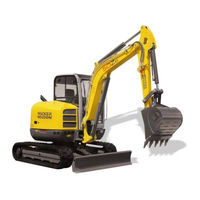
Wacker Neuson 6003 Operator's Manual (292 pages)
Track excavators
Brand:
Wacker Neuson
| Category:
Excavators
| Size: 27 MB
Table of Contents
Table of Contents
3
Introduction
13
Notices on this Operator's Manual
13
Abbreviations/Symbols
14
Machine Overview
15
Overview of Model Designations and Trade Names
16
Brief Description
16
Travelling Drive
16
Work Hydraulics
16
Shock Cartridges (Option)
16
Cooling System
16
Cab
17
Fields of Application, Attachments
18
Use: Attachment
18
Regulations
20
EC Declaration of Conformity for All Machines Delivered before 29 December 2009
21
EC Declaration of Conformity for All Machines Delivered after 29 December 2009
22
Declaration of Conformity for Machines Without CE Mark on the Type Label
23
EC Declaration of Conformity for All Machines Delivered after 29 December 2009
25
Declaration of Conformity for Machines Without CE Mark on the Type Label
26
Type Labels and Component Numbers
27
Signs and Symbols
30
Overview of Adhesive Labels
30
Overview of Safety Labels
35
Fire Extinguisher
40
Safety Instructions
41
Identification of Warnings and Dangers
41
Warranty
41
Disposal
41
Designated Use and Exemption from Liability
42
General Conduct and Safety Instructions
43
Organizational Measures
43
Selection and Qualification of Personnel, Basic Responsibilities
44
Safety Instructions Regarding Operation
45
Normal Operation
45
Information on Visibility
46
Checks When Reversing the Machine
47
Trailer Operation
47
Applications with Lifting Gear
48
Instructions on Fastening Loads
48
Prerequisite for Safe Use
49
Attachments
49
Safety Instructions for Maintenance
50
Warning of Special Hazards
52
Electrical Energy
52
Working in the Area of Underground Electric Lines
52
Working Near Overhead Electric Lines
52
Gas, Dust, Steam, Smoke
53
Hydraulic System
53
Noise
53
Oil, Grease and Other Chemical Substances
53
Using the Quickhitches in Water
53
Battery
54
Tracks
54
Hammer Operation
54
Safety Instructions
54
Working with a Hammer
55
Transport and Towing
55
Towing
55
Transport
55
Operation
57
Cab 50Z3/6003 (up to Serial No. AH02781)
58
Cab 50Z3 2 / 6003 2 (from Serial No. AJ02777)
60
Control Elements 6003 (Serial Nos. AH00579 to AH02750)
63
Control Elements 50Z3 2 / 6003 2 (from Serial No.aj02777)
65
Indicator Lights and Warning Lights (Overview)
67
Putting into Operation
70
Safety Instructions
70
Putting the Machine into Operation for the First Time
70
Running-In Period
70
Check Lists
71
Start-Up Checklist
71
Operation Checklist
72
Parking Checklist
72
Driving the Machine
73
Preheating Start Switch
73
Throttle
73
Automatic Engine Speed Setting
74
Before Starting the Engine
75
Starting the Engine: General
76
Jump-Starting the Engine (Supply Battery)
78
Starting at Low Temperatures
79
When the Engine Has Started
79
Special Instructions for Driving on Public Roads
80
Drive Position
80
Drive Levers
80
High Speed
81
Moving off
81
Hydraulic Brake
81
Mechanical Brake
81
Working on Slopes
82
Stabilizer Blade Operation
84
Parking the Machine
85
Parking the Machine on Slopes
85
Light System
86
Working Lights
86
Roof Lights (Option)
87
Interior Light
87
Rotating Beacon (Option)
88
Cab Heating and Ventilation
89
Summer/Winter Operation (up to Serial No. AD04650)
90
Heating Controls (from Serial No. AD04651)
90
Air Conditioning (Option)
91
Recirculated Air Mode
91
Wiper/Wash System
92
Tank for Washer System
92
Seat (50Z3)
93
Weight Adjustment
94
Height Adjustment
94
Horizontal Adjustment
94
Backrest Adjustment
94
Seat (6003)
95
Weight Adjustment
96
Horizontal Adjustment
96
Seat Depth Adjustment
96
Backrest Adjustment
96
Head Rests
97
Height Adjustment
97
Seat (Air Suspension Option)
98
Weight Adjustment
99
Height Adjustment
99
Horizontal Adjustment
99
Seat Depth Adjustment
99
Backrest Adjustment
100
Adjusting the Head Rest
100
Horizontal Suspension
100
Seat Belt
101
Retracting Lap Belt (Option)
102
Mirrors (Option)
103
Safety Instructions
103
Adjusting the Mirrors
104
Emergency Exit
105
Emergency Exit on Machines Equipped with Protective Front Guard Structures (Option)
105
Front Window (up to Serial No. AD06526)
106
Front Window (from Serial No. AD06527)
107
Opening the Front Window
107
Closing the Front Window
108
Opening the Lower Front Window
109
Closing the Lower Front Window
109
Opening the Whole Front Window
110
Closing the Whole Front Window
111
Opening the Front Window to a Gap
112
Opening and Closing the Side Window
112
Mounting/Removing the Canopy Shatter Protection (Option)
113
Door
114
Door 50Z3
114
Door 6003
114
Exit through the Door (up to Serial No. AH02764)
116
Exit through the Door (from Serial No. AJ02777)
117
Armrest Adjustment (up to Serial No. AH02764)
118
Armrest Adjustment (from Serial No. AJ02777)
119
Engine Cover
119
Battery Master Switch
120
Raising/Lowering the Cab
121
Towing the Machine
124
Crane Handling the Machine
125
Loading and Transporting the Machine
127
Safety Instructions
127
Tying down the Machine
128
Travelling Signal (Option)
128
Protective Structures
129
Definition of the Term "Protective Structure
129
Mechanical Integrity
129
Definition of Fops/Front Guard Categories
129
Responsibility for Machine Equipped with Protective Structures
129
Protective FOPS Structure/Small Screen - Category I (Option)
130
Protective FOPS Structure/Large Screen - Category II (Option)
131
Protective Front Guard Structure Category II (Option)
132
Shatter Protection (50Z3 Option)
134
Emergency Exit
136
Emergency Exit for Cab Equipped with Protective Front Guard Structure
136
Working with the Machine
138
General Safety Instructions
138
Control Levers/Iso Controls: Overview
139
Left-Hand Control Lever
139
Hammer Pedal Lock (up to Serial No. AH02781)
139
Boom/Triple Articulation Boom Operation (up to Serial No. AH02781)
140
Hammer Pedal Lock (from Serial No. AJ02777)
140
Boom/Triple Articulation Boom Operation (from Serial No. AJ02777)
141
Right-Hand Control Lever
141
Lowering the Boom with the Engine Stopped
141
Rotating the Upper Carriage
142
Swivel Unit Brake
142
Changeover Valve for SAE/ISO Controls (Option)
143
Left-Hand Control Lever
143
Right-Hand Control Lever
143
Directional Valve Position
143
Directional Valve
144
Control Lever with Proportional Controls (Option): Overview
145
Function
145
Left-Hand Control Lever
146
Changeover between Auxiliary Hydraulics and Boom Swivel
146
Switching the Status Indicator On/Off for Auxiliary Hydraulics/Boom Swivel
146
Operating the Boom/Auxiliary Hydraulics
147
Hammer Operation
147
Adjusting Control Response
148
Characteristic Curve Status Indicator
148
Lowering the Boom with the Engine Stopped
149
Releasing Pressure
149
Control Lever if Equipped with 3Rd Control Circuit (Option): Overview
150
Left-Hand Control Lever
150
Boom Swivel Controls (up to Serial No. AH02781)
150
Boom Swivel Controls (from Serial Number AJ02777)
151
Right-Hand Control Lever
151
Right-Hand Control Lever if Equipped with Proportionally Controlled 3Rd Control Circuit (Option)
152
Lowering the Boom with the Engine Stopped
152
Releasing Pressure
152
Tilting the Upper Carriage - Vertical Digging System (Option)
153
Operation (up to Serial No. AH02781)
154
Operation (from Serial No. AJ02777)
154
Vario (6003 Option)
155
Vario Operation
155
Driving Across Slopes with the Vario Feature
155
Risk Zone of the Vario Feature
156
Working with the Vario Feature
157
Improved Reach with the Vario Feature
157
Releasing the Pressure on the Operating Hydraulics
158
Releasing Pressure
158
Pressure Release with Proportional Controls (Option)
158
Re-Equipping Attachments
159
Specific Safety Instructions
159
Removing a Bucket
159
Installing a Bucket
160
Quickhitch (Option)
160
Hydraulic Easy Lock Quickhitch (Option)
162
Powertilt (Option)
166
Re-Equipping
166
Operation
167
Right-Hand Control Lever (Powertilt)
167
Connections for Auxiliary Hydraulics
168
Quickhitch Couplings
168
Safe Load Indicator (Option)
169
Safety Feature "Hose Burst Valve" (Option)
170
Applications with Lifting Gear
170
Lifting Gear Applications
171
Fastening Loads
171
Work Area Assessment and Preparation
171
Examining the Site
171
Preparing the Ground
171
Working with the Machine
172
Working with the Standard Bucket
172
Inadmissible Work
172
Work Position of Machine
173
Bucket Position When Digging
174
Excavating Trenches
174
Loading
175
Grading
175
Excavating Trenches Sideways
175
Working Alongside Trenches
176
Stabilizer Blade at Rear
176
Further Practical Hints for Digging
177
Loading Vehicles
177
Freeing the Machine
177
Grading
177
Troubleshooting
179
Engine Trouble
179
Indicator Lights
181
Seals, Hoses
181
Travel Gear
182
Engine Error Codes
183
Malfunctions of the Powertilt Unit
187
Troubleshooting the Central Lubrication System (Option)
188
Proportional Controls (Option) Diagnosis Display
189
Maintenance Introduction
191
Safety-Relevant Parts
191
Fuel System
192
Refuelling
193
Fuel-Filling Pump (Option) (up to Serial No. AD04862)
193
Fuel-Filling Pump (Option) (from Serial No. AD04863)
194
Stationary Fuel Pumps
194
Bleeding the Fuel System
195
Fuel Prefilter with Water Separator
196
Engine Lubrication System
197
Checking the Engine Oil Level
197
Adding Engine Oil
198
Engine and Hydraulics Cooling System
199
Specific Safety Instructions
199
Checking the Coolant Level/Adding Coolant
200
Air Filter
202
Replacing the Air Filter
203
Air Intake
204
Changing the Cab Air Filter
204
Replacing the Filter Element of the Air Conditioning System (Option)
205
Diesel Particulate Filter (Option)
206
Main Components of Diesel Particulate Filter System
206
How the Diesel Particulate Filter Works
207
Machine Operation with Diesel Particulate Filter
207
Display
209
Temperature Scale
209
Exhaust Gas Back Pressure Scale
209
Alarm Messages
210
Maintenance
211
Oils and Fuels
214
Troubleshooting
214
Warranty
214
V-Belt
215
Checking V-Belt Tension
215
Retightening the V-Belt
216
Checking the V-Belt of the Air Conditioning System (Option)
217
Tightening the V-Belt of the Air Conditioning System
217
Hydraulic System
218
Specific Safety Instructions
218
Checking the Hydraulic Oil Level
219
Adding Hydraulic Oil
220
Important Notices on the Use of Biodegradable Oil
221
Checking Hydraulic Pressure Lines
222
Tracks
223
Checking the Track Tension of the Rubber Tracks
223
Adjusting Track Tension
224
Travelling Drive
226
Checking the Oil Level and Adding Oil
226
Draining Oil
226
Maintenance of Attachments
227
Electrical System
227
Service and Maintenance Work at Regular Intervals
227
Instructions Concerning Specific Components
227
Alternator
227
Battery
228
General Maintenance Work
230
Cleaning
230
General Instructions for All Areas of the Machine
230
Inside the Cab
230
Cleaning the Seat Belt
231
Exterior of the Machine
231
Engine Compartment
231
Threaded Fittings and Attachments
231
Pivots and Hinges
231
Overview of Lubrication Points
232
Parking the Machine
233
Lubrication Points on the Boom, Bucket and Stick Rams
233
Lubrication Points on the Boom and Stick
234
Joint Rod Lubrication Point
235
Lubrication Points on the Stabilizer Blade and Stabilizer Blade Ram
235
Lubrication Points on the Slewing Ram and Swivelling Console
236
Lubrication Points of Ball Bearing Race of Live Ring
237
Lubrication Points of Live Ring Teeth
238
Powertilt Lubrication Points (Option)
239
Lubrication Points of Hydraulic Quickhitch (Option)
239
Lubrication Points of Control Lever Base (from Serial No. AJ02777)
240
VDS Lubrication Points (Option)
240
Central Lubrication System (Option)
241
Function
241
Status Leds
241
Adjusting Cycle Time and Lubrication Time
242
Repair in Case of Clogging
242
Preparatory Work before Taking out of Service
243
Maintenance if the Machine Is out of Service for a Longer Period of Time
243
Putting into Operation Again
243
Fluids and Lubricants
244
Oil Grades for the Diesel Engine, Depending on Temperature
245
Additional Oil Change and Filter Replacement (Hydraulic System)
245
Oil Grades for the Hydraulic System, Depending on Temperature
246
Maintenance Label
252
Explanation of Symbols on the Maintenance Label
252
Specifications
255
Chassis
255
Engine
255
Hydraulic System
256
Operating Hydraulics
256
Travel Gear and Swivel Unit
256
Stabilizer Blade
256
Electrical System, Model 50Z3
257
Fuse Box in Instrument Panel
257
Main Fuse Box with Relays Underneath the Cab
257
Relays
258
Electrical System, Model 6003 (from Serial No. AH0611)
258
Fuse Box on Instrument Panel (up to Serial No. AH02750)
258
Main Fuse Box with Relays
259
Fuse Box on Instrument Panel (from Serial No. AJ02777)
259
ECU Control Unit (6003 from Serial No. AH00611)
260
Noise Levels
260
Vibration
260
Coolant Compound Table
263
Powertilt
263
Weight Indications
264
Dimensions Model 50Z3
265
Dimensions Model 50Z3 VDS
267
Dimensions Model 6003 Standard Boom, Vario (Option)
269
Dimensions Model 6003 Triple Articulation Boom (Option)
271
Lift Capacity Table 50Z3
273
Lift Capacity Table 50Z3 Counterweight (Option)
274
Lift Capacity Table 50Z3 Long Stick (Option)
275
Lift Capacity Table 50Z3 Long Stick, Counterweight (Option)
276
Lift Capacity Table 50Z3 VDS Short Stick (Option)
277
Lift Capacity Table 50Z3 VDS Short Stick, Counterweight (Option)
278
Lift Capacity Table 50Z3 VDS Long Stick (Option)
279
Lift Capacity Table 50Z3 VDS Long Stick, Counterweight (Option)
280
Lift Capacity Table 6003
281
Lift Capacity Table 6003 Counterweight (Option)
282
Lift Capacity Table 6003 Long Stick (Option)
283
Lift Capacity Table 6003 Long Stick, Counterweight (Option)
284
Lift Capacity Table 6003 Long Stick, Triple Articulation Boom (Option)
285
Lift Capacity Table 6003 Triple Articulation Boom (Option)
287
Lift Capacity Table 6003 Triple Articulation Boom, Counterweight (Option)
288
Lift Capacity Table 6003 Vario (Option)
289
Applications with Lifting Gear
290
Advertisement
Wacker Neuson 6003 Operator's Manual (20 pages)
Track Excavator
Brand:
Wacker Neuson
| Category:
Excavators
| Size: 2 MB
Table of Contents
Introduction
2
Important Operator Information
2
Special Instructions
2
Abbreviations / Symbols
2
Machine Overview
3
Brief Description
4
Fields of Application, Attachments
5
Possible Attachments
5
Operator Qualifications
6
EC Declaration of Conformity Version 50Z3 up to Serial Number AH00578
7
EC Declaration of Conformity Version 50Z3 from Serial Number AH00579
8
EC Declaration of Conformity Version 6003 up to Serial Number AH00578
9
EC Declaration of Conformity Version 6003 from Serial Number AH00579
10
Type Labels and Component Numbers
11
Serial Number
11
Cab Certification Number
11
Engine Identification Number
12
Label Overview
13
Symbols
14
Options
15
Safety Labels
16
Fire Extinguisher
19
Advertisement
Related Products
Wacker Neuson 60032
Wacker Neuson Dumper 6001
Wacker Neuson 620048
Wacker Neuson 620026
Wacker Neuson 620054
Wacker Neuson 1000164553
Wacker Neuson 1404
Wacker Neuson 2503
Wacker Neuson 28Z3
Wacker Neuson 28Z3 VDS
Wacker Neuson Categories
Power Tool
Portable Generator
Construction Equipment
Water Pump
Excavators
More Wacker Neuson Manuals
Login
Sign In
OR
Sign in with Facebook
Sign in with Google
Upload manual
Upload from disk
Upload from URL