Table of Contents
Advertisement
Quick Links
Advertisement
Table of Contents

Related Manuals for Roadragon G-V803


Summary of Contents for Roadragon G-V803
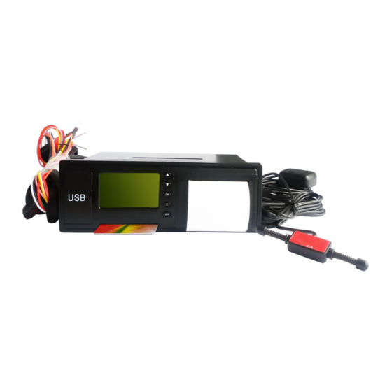
- Page 1 Speed Governor GPS Vehicle tracker Tachograph G-V803 User manual...
-
Page 2: Table Of Contents
I. Preface-----------------------------------------------------------------3 II. Features & Functions---------------------------------------------------4 1. Features------------------------------------------------------------4 2. Functions-----------------------------------------------------------5 3. Operation Specification--------------------------------------------6 1) Parameter Setting-----------------------------------------------6 2) The Basic Parameter Setting-------------------------------------6 3) Data Collection---------------------------------------------------7 4) Data Print--------------------------------------------------------7 III. View & Wiring Diagram------------------------------------------------7 1. View--------------------------------------------------------------7 2. I/O Ports----------------------------------------------------------8 3. Serial Ports-------------------------------------------------------8 4. -
Page 3: Preface
Based on years of experience in vehicle electronic industry and a long term of hard work, our company has researched and developed GPS vehicle Tracker with tachograph and speed Governor function G-V803, which is a high performance digital and electric recording device with a set of embedded MCU. -
Page 4: Features & Functions
II. Features & Functions 1. Features Real-time GPS tracking Real-time vehicle status monitoring Vehicle Immobilization Control GPS mileage report and mileage pulse report (Traffic black box) Accident doubtful points and record analyzing function Geo-Fence with 108 rectangle area ... -
Page 5: Functions
Use IC card to record the driver’s code and driver’s license code to ID record identify and record the ID. Check whether the current driving achieve to the fatigue driving Fatigue driving threshold value, and will have fatigue alarm Print the vehicle information(include vehicle No., driver’s code, driver Printer function license No., print time etc) average speed in the last 15 minutes and fatigue driving record. -
Page 6: Operation Specification
Remote parameter setting and check: VIN, vehicle No., vehicle Parameter setting classification, driver’s code, driver’s license No., characteristic and checking parameter. The terminal record the vehicle’s driving status in 360 hours use<=1 Status record minute as the interval. Electronic mileage: the terminal calculates the driving mileage by the Mileage statistics vehicle speed sensor. -
Page 7: Data Collection
Set the device’s parameter: the vehicle’s maximum speed limit, vehicle’s No., VIN, vehicle’s classification, fatigue driving time (default as 4 hours), the shortest relax time. 3) Data collection You can use USB stick and RS232 port to collect the data. Data collection would not change or delete the saved data in running recorder. -
Page 8: I/O Ports
2. I/O ports 3. Serial ports... -
Page 9: Wiring Diagram
4. Wiring diagram... - Page 10 Function Specification Note Power + DC 9V~36V Power - Negative signal Left steering lamp Detect 8V-36V effective Right steering lamp Detect 8V-36V effective High beam line Detect 8V-36V effective Brake signal line Detect 8V-36V effective Magnetometer signal line Check door open or not Vibration sensor check Check taking...
-
Page 11: Installation Debug Specification
signal line Custom output low signal O Output ground signal that means taking iron AD voltage checking 2 Checking 0-24V voltage Ground AD voltage checking Detect 0-24V voltage 5. Installation debug specification You should insert an effective SIM card that supplied by driver to the relevant position of the host device after you finished installing the line connection checking. - Page 12 SMS already read Preserved No. Client group Code group Configuration achieved Preserve SMS Load has completed Read SMS Received SMS Already dispatch cars Dial No. Call history Car arrived behind time Received calls Already arrived safety Unreceived calls Already return safely Clear all records Ask change road drive Display setting...
-
Page 13: How To Set On The Lcd Screen Menu
7. How to Set on the LCD Screen Menu 1) Preserve No. The preserved number is the number preset in the terminal. Menu Group team Group numbers options (you can dial the numbers by the preserved number of the terminal) 2) SMS This device can save the SMS, and send SMS. -
Page 14: Parameter Settings
Modify the User’s password 5. Download data Menu Advanced options Download data When you connect with USP cable, then you can download these materials from the terminal: accidents doubt points file, USB file, USB upgrade program(you should input 666666 when you download the terminal program), 9. - Page 15 Ex. you input 13812345678 Note:only can input the 11-digit number. 2. Set the UDP parameter (Input factory password) Menu Factory settings Set up UDP parameter Set up the UDP IP and port and the terminal online, Format: 0,IP,port, Ex. 0,192.168.001.001,8888 (If the IP is less than 3 bits, you can add 0 before that) 3.
- Page 16 8. Set the sensor coefficient (input factory password) Menu Factory settings Sat the sensor’s factors, The sensor coefficient’ configuration (the vehicle’s characteristics coefficient), such as 680, every vehicle’s coefficient are different, you must set it according to different conditions. 9. Set the factory code input factory password) Menu Factory settings...
-
Page 17: Technical Parameters
IV. Technical Parameters Items Parameter Dimension 190mm*155mm*58mm Weight 600g Input Voltage DC 12V~36V Operation current 200mAh/12V (3,000mAh when printing) Operating -20℃~75℃ temperature Humidity 5%~95% Work Time 2 hours in normal mode LCD screen 2.3”(2.8*5.5cm) Integrated thermal Printer Trip mileage 0~999,999.9km measurement range Monitoring speed... -
Page 18: How To Set Speed Governor
interval Monitoring speed 0~255Km/h range Position accuracy: <10 m; Position time: <15 seconds Re-capture: <45 seconds Hot start: about 20 seconds Cold start: <=150 seconds GPRS Class 10: Multi-time buttress function Support GSM900/DCS1800 GPRS GSM07.07, GSM07.05 and strength AT command; Launch power: Class 10;... -
Page 20: Wire Connection Of Relay
Please find the corresponding car cable connection. P.S. : pin1 pin2 connected to the car battery. pin11 is connected to the vehicle speed sensor. ( if choose gps speed mode,do not connect the speed sensor wire ) pin12 is connected to the car ACC line . pin19 pin20 is connected to the relay 's positive and negative levels. -
Page 21: Set Speed Mode & Sensing Factor
4. Set Speed Mode & Sensing Factor notice: Whether you choose GPS speed mode , or electronic speed mode , you need to set the correct speed sensing factor.make sure speed value displayed on the LCD screen is the same as speedometer. After the speed sensor coefficient set up, please keep 20kmh(or>20 kmh) and driving more than 5 minutes, the system will automatically set up a proper sensing factor. -
Page 22: Online Tracking Setup
VI. Online Tracking Setup 1. Set online To edit 1st SMS and send to terminal as below <SPBSJ*P:BSJGPS*T:219.133.034.198,6690*U:219.133.034.198,6688*A:CMNET*N:1341 8181818> SPBSJ is fixed header P: Password T: TCP IP&Port P: UDP IP&Port Note: IP should 3 digits. If not, please add 0 instead, e.g. 034 instead of 34. A: APN N: GPS tracker No. -
Page 23: Check On Platform
3. Check on platform Our company’s GPS tracking server add:174.142.53.69:8089/ Input account number and password Click “Home” and select your car. -
Page 24: Note
Check the car’s status VII. Note ◆ Do not put the device into the water. ◆ Keep the vehicle’s storage battery full, working normal. ◆ Don’t try to press the “SOS alarm button”, you should be responsible for the false alarm. ◆... -
Page 25: Viii.after-Sale Service
Our technicians will keep in touch with seller after receiving the defective products. And buyer shall provider all the necessary information needed. X. Packing list Standar Package Optional accessories G-V803 Vehicle tachograph * 1pc Fuel sensor GPS antenna * 1pc Temperature sensor GSM antenna * 1pc...
Need help?
Do you have a question about the G-V803 and is the answer not in the manual?
Questions and answers