
Related Manuals for Ludlum Measurements 3014


Summary of Contents for Ludlum Measurements 3014
- Page 1 Model 3014 Dual-Detector Digital Survey Meter/SCA Ludlum Measurements March 2021 Serial Number: 25020730 and Succeeding Firmware: F.2.1.1229 and Higher...
- Page 3 Model 3014 Dual-Detector Digital Survey Meter/SCA Ludlum Measurements March 2021 Serial Number: 25020730 and Succeeding Firmware: F.2.1.1229 and Higher...
- Page 5 STATEMENT OF WARRANTY Ludlum Measurements, Inc. warrants the products covered in this manual to be free of de- fects due to workmanship, material, and design for a period of twelve months from the date of delivery. The calibration of a product is warranted to be within its specified accuracy lim- its at the time of shipment.
-
Page 7: Table Of Contents
Setup Mode Operation ....... . . 39 Model 3014 List of Parameters (in order) ..... . . 41 Page 1 - Device . - Page 8 AuxComm Setting - Write Protect ..... . 95 A.4.5 AuxComm Setting - Encryption ......96 Ludlum Measurements, Inc.
- Page 9 CONTENTS A.4.6 AuxComm Setting - Auto Mode Interval ....96 March 2021...
-
Page 11: List Of Figures
IST OF IGURES Startup Display (All Segments Shown) ......14 Hardware Revision Levels ........14 Firmware Version Display . -
Page 13: List Of Tables
IST OF ABLES COUNT Mode Units and Result ......26 Features That Affect Units in All Modes ......80 A.1 AuxComm Mode . -
Page 15: Introduction
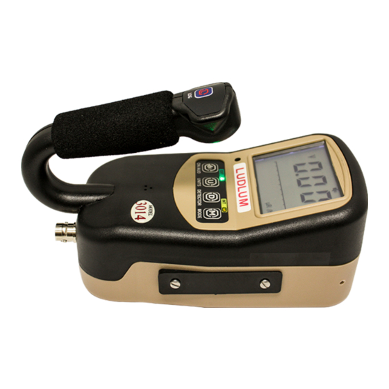
The Model 3014 is an ergonomic, lightweight instrument which can be used for radiation survey purposes. The Model 3014 includes an internal detector for tracking user exposure rate or dose. The Model 3014 features the ability to measure radiation in count rate, exposure rate/dose, activity rate, integrated exposure/dose, time-averaged rates, and scaler counts. - Page 16 It is located to the left of the detector connector. If a headphone jack is not in use, the Model 3014 may optionally be provided with an RS-232 serial output for connection to PC or other electronic device.
-
Page 17: Getting Started
Check individual item serial numbers and ensure calibration certificates match between instruments and de- tectors (if applicable). The Model 3014 serial number is located on a label on the front side of the unit. -
Page 18: Turning The Instrument On
The instrument then displays the current revision level of each board installed in the system: main board, internal detector high-voltage board, and auxiliary communications board. Figure 2.2: Hardware Revision Levels A revision level of 0 indicates that the board is not installed or detected. Next, the instrument displays the firmware version. Ludlum Measurements, Inc. -
Page 19: Firmware Version Display
2.3. TURNING THE INSTRUMENT ON Figure 2.3: Firmware Version Display The first character defines the firmware type, the second character defines the major version level, and the third character defines the revision level. The build version is not displayed. The instrument then displays the battery voltage. The low-battery indicator is only displayed to indicate that the value displayed is related to the battery voltage and not that the battery voltage is low. -
Page 20: Instrument Operational Test
If desired, multiple readings may be taken at different distances and/or with different sources so that other scales are checked. Example of a Check Source reading: Check Source # Rate Units Once this procedure has been completed, the instrument is ready for use. Ludlum Measurements, Inc. -
Page 21: Sigma Audio
2.6 Detector Failure Diagnostic Note that the Model 3014 has its own diagnostic tests to ensure that the detector is function- ing correctly. The Model 3014 can detect when the radiation detector is malfunctioning and will flash the display to indicate a fault. -
Page 22: Detector Over Max
Figure 2.8: Detector Over Range (Display Will Flash) 2.6.4 Detector Overload As another diagnostic test, the Model 3014 monitors the HV supply’s detector current. A current overload threshold can be set via Setup Mode. (A setting of 0 disables this alarm.) In general, this alarm setting can be used to detect when there is some detector failure, a cable failure, or a possible high level of radiation. -
Page 23: Instrument Use And Controls
By default, the majority of functions are assigned to short presses of the buttons. 2.7.1 ON/AUD Button: Used to power the Model 3014 ON and OFF and adjust the audio level (mute, low, medium, or high). • Power On: Press for approximately one second and release (all LCD segments will ac- tivate and firmware version will be shown). -
Page 24: Units Button
Short Press (press and release after one beep): • Used to switch between Primary and Secondary units (or Tertiary units in the case of alpha/beta configuration) in all available modes. Long Press (press and release after two beeps): Ludlum Measurements, Inc. -
Page 25: Detector Button
2.7. INSTRUMENT USE AND CONTROLS • Currently has no effect. Extra-Long Press (press and release after three beeps): • Enables/disables the Auxiliary Communications as indicated by a wifi symbol on the top of the LCD screen. Figure 2.10: WiFi Symbol 2.7.3 DETECTOR Button: The Detector button’s primary function is to switch between available enabled detectors. -
Page 26: Log Button
• If datalogging in Mode 2 and a log event has been initiated, the button is used to accept the current location ID. Long Press (press and release after two beeps): • Currently has no effect. Extra-Long Press (press and release after three beeps): • In COUNT mode, it will: Ludlum Measurements, Inc. -
Page 27: Rate Mode Operation
2.8. RATE MODE OPERATION – If COUNT mode is ready: It will change the count time to next available count time. – If COUNT mode is in progress: It will switch between displaying the count and displaying the count timer. –... -
Page 28: Max Mode Operation
Prede- fined count times of 6 seconds, 30 seconds, 1 minute, 2 minutes, 5 minutes, and 10 minutes are available as well as a user-defined count time and continuous counting operation (count Ludlum Measurements, Inc. - Page 29 2.10. COUNT MODE OPERATION time displayed as 0). The maximum user-defined count time is 999e6 (999000000) seconds or approximately 31.68 years. Predetermined count times will be displayed in clock mode. User-defined count times will be displayed in clock mode if less than 10 hours; otherwise, they will be displayed in second counts until 10 hours remain.
- Page 30 • An extra-long press of the LOG button will change the count time to the next available time. When the Count Timer is Active: • The display will show either Count Time (default), both Count Time and Counts, or just counts, depending on Device Count Display Mode. Ludlum Measurements, Inc.
- Page 31 2.10. COUNT MODE OPERATION • a long press of the ON/AUD button will reset the Count Timer (and not log results if previously requested). • Click audio, if enabled, can be adjusted by a short press of the ON/AUD button. •...
-
Page 32: Dose Mode Operation
Alarms are latching in DOSE Mode. Under an alarm condition, the ALARM display indicator will remain on until the display is reset. If other operational modes are available, a short press of the MODE button will move to the next available operational mode. Ludlum Measurements, Inc. -
Page 33: Dose Mode Operation Display
2.11. DOSE MODE OPERATION A short press of the LOG button, if datalogging is enabled, will log the currently displayed DOSE value. Figure 2.15: DOSE Mode Operation Display March 2021... -
Page 35: Specifications
PECIFICATIONS External Detector: may be Geiger-Mueller (GM), scintillator, or proportional Internal Detector: one energy-compensated GM tube Energy Response: within 25% of true value from 60 keV to 3 MeV Linearity: readings within 10% of true value LCD Display: three-digit LCD with bar graph, 11 units, five multipliers, two mode icons, three alarm levels, and four fault messages, as well as USB, wireless, audio, and low-battery icons Alarms: three adjustable count rate, exposure/dose, count, and accumulated dose alarm... - Page 36 Environmental Rating: NEMA (National Electrical Manufacturers Association) rating of 3x or IP (Ingress Protection) rating of 53 Size: 16.5 x 11.4 x 21.6 cm (6.5 x 4.5 x 8.5 in.) (H x W x L) Weight: 0.9 kg (2.0 lb) (excluding detectors and clips) Ludlum Measurements, Inc.
-
Page 37: Setup Mode
4.1 Setup Overview Your instrument has been shipped from Ludlum Measurements only after passing electronic checkout, a 24-hour burn-in process, and a careful calibration process. Calibration papers are supplied with each instrument shipped from Ludlum Measurements. -
Page 38: Setup Parameters
Calibration Constant Exponent Dead Time 36 e-6 10 e-6 5 e-6 5 e-6 80 e-6 Correction 1 Dead Time Correction 2 Mantissa Dead Time Correction 2 Exponent Detector Current Overload Threshold Detector Adjustable 0 (continuous) Scaler Count Ludlum Measurements, Inc. - Page 39 4.2. SETUP PARAMETERS Model Model Alpha Model Internal Setting Setup Parameter 133-6 44-2 or Beta 42-31H Detector Detector Active Area Channel 1 – 0.035 0.035 0.0035 0.004 0.035 Threshold (V) Channel 1 - Window 0 (max value) 0.03 0 (max value) Channel 1 - Efficiency Channel 1 - Loss of...
- Page 40 0 (No unit) Alarm 1 kcpm Unit 3 - RATE / MAX 5.00 0 (No unit) 0 (No unit) Alarm 2 kcpm Unit 3 - RATE / MAX 8.00 0 (No unit) 0 (No unit) Alarm 3 kcpm Ludlum Measurements, Inc.
-
Page 41: Entering Setup Mode
4.3. ENTERING SETUP MODE Model Model Alpha Model Internal Setting Setup Parameter 133-6 44-2 or Beta 42-31H Detector Unit 3 - COUNT Units and Minimum 0 (No unit) 000 c 0 (No unit) Display Unit 3 - COUNT 0 (No unit) 2.00 kc 0 (No unit) Alarm 1... -
Page 42: Backlight/Setup Protect Dipswitch
SETUP PROTECT: The Model 3014 parameters can be protected from unauthorized changes via the internal switch located on the Model 3014 circuit board. To change the switch, open the battery compartment and remove the batteries from the Model 3014. Next, loosen the six pan-head screws that fasten the bottom cover. -
Page 43: Setup Mode Operation
Lumic 2.0 Calibration Software. 4.4 Setup Mode Operation Once the Model 3014 is in Setup mode, setup page selection will be displayed on the LCD. Short press the MODE or ON/AUD button to choose the Setup Page you are interested in. -
Page 44: Setup Page Selection Display (Showing Page 4-Cal)
UNIT button for 2 seconds to close setting. Press the UNIT button for 2 seconds to return to the page selection menu. Press the UNIT button for 2 seconds to exit Setup. The list below shows the nine setup pages and the parameters in order, on each page. Ludlum Measurements, Inc. -
Page 45: Model 3014 List Of Parameters (In Order)
4.5. MODEL 3014 LIST OF PARAMETERS (IN ORDER) 4.5 Model 3014 List of Parameters (in order) Page 1 - dev • Multi-level Audio • Backlight Threshold • Auto Shutdown Time • Auxiliary COM • Real Time Clock Month • Real Time Clock Day •... - Page 46 • Channel 2 - Efficiency • Channel 2 - Loss of Count Alarm Time • Channel 2 - Icon Page 7 - U-1 • Unit 1 - RATE/MAX Units and Minimum Display • Unit 1 - RATE/MAX Maximum Display Ludlum Measurements, Inc.
- Page 47 4.5. MODEL 3014 LIST OF PARAMETERS (IN ORDER) • Unit 1 - RATE/MAX Alarm 1 • Unit 1 - RATE/MAX Alarm 2 • Unit 1 - RATE/MAX Alarm 3 • Unit 1 - COUNT Units and Minimum Display • Unit 1 - COUNT Alarm 1 •...
-
Page 48: Device
Finally, extra-long pressing the UNIT button will complete the modification. Default settings are in bold. Multi-level Audio - Upon entry into Multi-level Audio, the parameter will be selected (flash- ing) indicating the state of the parameter. • on (audio selection: off/low/med/high) • off (audio selection: off/on) Ludlum Measurements, Inc. - Page 49 4.6. PAGE 1 - DEVICE Use the MODE and ON/AUD buttons to scroll through the available parameter options. Backlight Threshold - Upon entry into the Backlight Threshold, the parameter will be se- lected (flashing) indicating the state of the parameter. •...
- Page 50 • 00 - 59 (seconds of the minute) Use the MODE and ON/AUD buttons to scroll through the parameter options. Please note that when exiting the parameter, even if no changes were made, the seconds parameter will automatically be reassigned the frozen value. Ludlum Measurements, Inc.
-
Page 51: Datalogging
4.7. PAGE 2 - DATALOGGING 4.7 Page 2 - Datalogging To begin adjusting a device parameter, short press the MODE and ON/AUD to scroll through the available device parameters. To begin, short press UNIT to begin modifying the param- eter chosen. Finally, extra-long pressing the UNIT button will complete the modification. Default settings are in bold. -
Page 52: Configuration
If no modes were enabled rate mode will automatically be enabled for external detectors, and dose mode will be enabled for internal detectors. Ludlum Measurements, Inc. - Page 53 4.8. PAGE 3 - CONFIGURATION Bar Graph Mode - Upon entry into Bar Graph Mode, the parameter will be selected (flashing) indicating the state of the parameter. • off (no bar graphing) • Std (standard bar graphing mode - decade) •...
-
Page 54: Calibration
High Voltage - Upon entry into High Voltage, one of the following parameters will be selected (flashing). • Ones Place (0-9) • Tens Place (0-9) • Hundreds Place (0-9) • /k Multiplier with all digits flashing (on/off) Ludlum Measurements, Inc. - Page 55 4.9. PAGE 4 - CALIBRATION Use the UNIT button to select the appropriate parameter, and use the MODE and ON/AUD buttons to scroll through the parameter options. The k multiplier also activates left-most decimal point. If k multiplier is used, Hundreds Place becomes the Thousands Place, Tens Place becomes the Hun- dreds Place, and Ones Place becomes the Tens Place.
- Page 56 Detector Adjustable Scaler Count Time - Upon entry into Detector Adjustable Scaler Count Time, one of the following parameters will be selected (flashing). • Rightmost Digit (0-9) • Middle Digit (0-9) • Leftmost digit (0-9) • <>/k/M Multiplier with all digits flashing (adjustable from xxx to xxx M) Ludlum Measurements, Inc.
-
Page 57: Channel 1
4.10. PAGE 5 - CHANNEL 1 Use the UNIT button to select the appropriate parameter, and use the MODE and ON/AUD buttons to scroll through the parameter options. Detector Active Area - Upon entry into Detector Active Area, one of the following parameters will be selected (flashing). - Page 58 Channel 1 - Icon - Upon entry into Channel 1 Icon, one of the following parameters will be selected (flashing). • – Alpha icon • – Beta icon • – Gamma icon • n - Neutron icon • • Ludlum Measurements, Inc.
-
Page 59: Channel 2
4.11. PAGE 6 - CHANNEL 2 • • , , & • • • , , & n • • , , & n • , , & n • , , , & n • 0FF – No icon Use the MODE and ON/AUD buttons to scroll through the available parameter options. - Page 60 Channel 2 - Icon - Upon entry into Channel 2 Icon, one of the following parameters will be selected (flashing). • – Alpha icon • – Beta icon • – Gamma icon • n - Neutron icon • Ludlum Measurements, Inc.
-
Page 61: Unit 1
4.12. PAGE 7 - UNIT 1 • • • , , & • • • , , & n • • , , & n • , , & n • , , , & n • 0FF – No icon Use the MODE and ON/AUD buttons to scroll through the available parameter options. - Page 62 Unit 1 - RATE/MAX Alarm 3 - Upon entry into Unit 1 RATE/MAX Alarm 3, one of the following parameters will be selected (flashing). • Rightmost Digit (0-9) • Middle Digit (0-9) Ludlum Measurements, Inc.
- Page 63 4.12. PAGE 7 - UNIT 1 • Leftmost Digit (0-9) • Multiplier with all digits flashing (adjustable from x.xx to xxx M depending on unit selected) Use the UNIT button to select the appropriate parameter, and use the MODE and ON/AUD buttons to scroll through the parameter options.
- Page 64 Use the UNIT button to select the appropriate parameter, and use the MODE and ON/AUD buttons to scroll through the parameter options. Unit 1 - DOSE Alarm 2 - Upon entry into Unit 1 Dose Alarm 2, one of the following parame- ters will be selected (flashing). Ludlum Measurements, Inc.
- Page 65 4.13. PAGE 8 - UNIT 2 • Rightmost Digit (0-9) • Middle Digit (0-9) • Leftmost Digit (0-9) • Multiplier with all digits flashing (adjustable from x.xx to xxx M depending on unit selected) Use the UNIT button to select the appropriate parameter, and use the MODE and ON/AUD buttons to scroll through the parameter options.
-
Page 66: Unit 2
Use the UNIT button to select the appropriate parameter, and use the MODE and ON/AUD buttons to scroll through the parameter options. Unit 2 - RATE/MAX Alarm 2 - Upon entry into Unit 2 RATE/MAX Alarm 2, one of the following parameters will be selected (flashing). Ludlum Measurements, Inc. - Page 67 4.13. PAGE 8 - UNIT 2 • Rightmost Digit (0-9) • Middle Digit (0-9) • Leftmost Digit (0-9) • Multiplier with all digits flashing (adjustable from x.xx to xxx M depending on unit selected) Use the UNIT button to select the appropriate parameter, and use the MODE and ON/AUD buttons to scroll through the parameter options.
- Page 68 Display, one of the following parameters will be selected (flashing). Note: Select Unit first before selecting multiplier. • Multiplier with all digits flashing (adjustable from x.xx to xxx M depending on unit selected) • Unit (off, d, c, Rem, R, Sv) Ludlum Measurements, Inc.
- Page 69 4.13. PAGE 8 - UNIT 2 Use the UNIT button to select the appropriate parameter, and use the MODE and ON/AUD buttons to scroll through the parameter options. Unit 2 - DOSE Alarm 1 - Upon entry into Unit 2 Dose Alarm 1, one of the following parame- ters will be selected (flashing).
-
Page 70: Unit 3 (If Supported)
Use the UNIT button to select the appropriate parameter, and use the MODE and ON/AUD buttons to scroll through the parameter options. Unit 3 - RATE/MAX Maximum Display - Upon entry into Unit 3 RATE/MAX Units Maximum Display, one of the following parameters will be selected (flashing). • Rightmost Digit (0-9) Ludlum Measurements, Inc. - Page 71 4.14. PAGE 9 - UNIT 3 (IF SUPPORTED) • Middle Digit (0-9) • Leftmost digit (0-9) • Multiplier with all digits flashing (adjustable from x.xx to x.xx k) Use the UNIT button to select the appropriate parameter, and use the MODE and ON/AUD buttons to scroll through the parameter options.
- Page 72 Unit 3 - COUNT Alarm 2 - Upon entry into Unit 3 Count Alarm 2, one of the following pa- rameters will be selected (flashing). • Rightmost Digit (0-9) • Middle Digit (0-9) • Leftmost digit (0-9) • Multiplier with all digits flashing (adjustable from x.xx to xxx M depending on unit selected) Ludlum Measurements, Inc.
- Page 73 4.14. PAGE 9 - UNIT 3 (IF SUPPORTED) Use the UNIT button to select the appropriate parameter, and use the MODE and ON/AUD buttons to scroll through the parameter options. Unit 3 - COUNT Alarm 3 - Upon entry into Unit 3 Count Alarm 3, one of the following pa- rameters will be selected (flashing).
- Page 74 • — (Internal Detector Only) • 1 2 (Channel 1 + Channel 2) • 1-2 (Channel 1 - Channel 2) • 2-1 (Channel 2 - Channel 1) Use the MODE and ON/AUD buttons to scroll through the parameter options. Ludlum Measurements, Inc.
-
Page 75: Reset (Warning!!!)
4.15. PAGE 10 - RESET (WARNING!!!) 4.15 Page 10 - Reset (WARNING!!!) In the event of an instrument issue that requires major modification to the stored instru- ment values, an instrument reset has been incorporated, which will wipe out all stored in- formation in the device with the exception of hardware calibration information from the fac- tory. -
Page 77: Datalogging
The datalogging feature of the Model 3014 allows the user to log radiation readings with the use of a handle-mounted LOG button. Data can be logged in any of the Model 3014’s oper- ational modes (RATE, MAX, and COUNT). Up to 1000 data points can be taken and stored internally. -
Page 78: Datalogging Operation - Mode 2
– For a continuous Scaler count (Scaler time is 0), the LOG button is enabled at all times. • The LCD display will show a possible Location ID Table index for the user. The index will be auto-incremented from the previously used index. Ludlum Measurements, Inc. -
Page 79: Datalogging Operation - Mode 3
5.3. DATALOGGING OPERATION – MODE 3 Figure 5.2: Displaying Datalog Location ID Table Index of 36 • The number will be blinking, indicating a changeable value. The user may then enter the preferred Location ID Table index by a short press of the MODE (to increment the value) or ON/AUD (to decrement the value) buttons as in Setup mode. -
Page 80: Format
• Mode (1 Byte) • Detector Number (1 Byte) • Status (1 Byte) • Reserved (2 Bytes) • Elapsed Count Time in seconds (4 Bytes) • Scaler Count Time in seconds (4 Bytes) • Location ID (32 Bytes) Ludlum Measurements, Inc. -
Page 81: Software
OFTWARE 6.1 Connecting to Software The Model 3014 software is sent with a standard two-meter cable. (A five-meter cable can be provided if requested. However, any cable longer than two meters may have issues with some USB hubs and computers, typically laptops.) To connect an instrument to the computer, please connect one end of the USB cable to the instrument first, and then the other end to the computer. -
Page 83: Advanced Features
DVANCED EATURES 7.1 Dead Time Correction All pulse counting detectors have a “dead time” in which the detector is unable to register another event. In relatively low fields this is not an issue. However, as the field strength approaches the high end of the detector’s range, dead time causes the pulse rate to become non-linear with respect to the real radiation field. -
Page 84: R To Sv Conversion
However, if calibration is required (due to board rework, etc.) the calibration settings are available in Lumic Calibra- tion software. 7.6 Other Device Data The following parameters on the instrument allow recording import device information within the device: Ludlum Measurements, Inc. -
Page 85: Battery Life
7.7. BATTERY LIFE Firmware Version: This is a read-only presentation of the firmware version. With a firmware version of F.x.y.zzzz, the F.x.y will show up on the device screen during the power-on sequence and signifies the released version. Device – Model Name: This should match the model name on the front face of the instrument. -
Page 87: Safety Considerations
Not certified for use in an explosive atmosphere 8.2 Warning Markings and Symbols The Model 3014 Survey meter is marked with the following symbols: CAUTION (per ISO 3864, No. B.3.1): designates hazardous live voltage and risk of electric shock. During normal use, internal components are hazardous live. -
Page 88: Cleaning And Maintenance Precautions
Ludlum Mea- surements, Inc. 8.3 Cleaning and Maintenance Precautions The Model 3014 may be cleaned externally with a damp cloth, using only water as the wetting agent. Observe the following precautions when cleaning or performing maintenance on the instru- ment: •... -
Page 89: Revision History
EVISION ISTORY This section of the manual will be updated with each revision of theModel 3014 in order to document changes over time. Ludlum Measurements’ policy is to provide free software upgrades to instruments for the life of the instrument. -
Page 91: Recycling
To this end, Ludlum Measurements, Inc. strives to supply the consumer of its goods with information regarding reuse and recycling of the many different types of materials used in its products. -
Page 93: Options
It allows administrators to adjust device datalogging parameters. Headphone Option (part # 4498-555): This provides the Model 3000 series of instruments with a jack and circuitry required for a standard headphone plug. Ludlum Measurements also offers mono/stereo headphones with volume control. -
Page 95: A Auxiliary Communications
UXILIARY OMMUNICATIONS A.1 AuxComm Overview AuxComm, short for Auxiliary Communications, is a feature included on certain Ludlum in- struments. An AuxComm port allows the instrument to expand its capabilities with a variety of external devices through a standard serial interface. A.2 Requirements In order to take advantage of the AuxComm functionality, you will need the following: •... -
Page 96: Auxcomm Usage - Pairing
4. Use 2-second Enable hot key to turn on WiFi. 5. Select “Scan” in App/Software. 6. When instrument is found by mobile device, select device in list and then “Pair.” 7. Enter PIN in App/Software from Step 2. Ludlum Measurements, Inc. - Page 97 A.3. USAGE Figure A.1: Example – Device Selection Figure A.2: Example – Pairing In Lumic Linker App (iOS) Figure A.3: Example – Model 3000 series Figure A.4: Example – Entering PIN In Found in Lumic Linker App (iOS) Lumic Linker App (iOS) March 2021...
-
Page 98: Settings
Raw Count: Mode that automatically transmits raw, uncorrected counts. The count interval is based on the AuxComm Auto Mode Interval variable. The output value is the cumulative counts that occurred in the previous interval on all enabled channels. Ludlum Measurements, Inc. -
Page 99: Auxcomm Setting - Off Time
A.4. SETTINGS CPM: Mode that automatically transmits the CPM (counts per minute) for the external de- tector no matter what detector or mode is currently being displayed. The count interval is based on the AuxComm Auto Mode Interval variable. Display: Mode that automatically transmits the numeric value as well as units prefix, units, and units suffix for the currently displayed screen. -
Page 100: Auxcomm Setting - Encryption
The table below shows valid settings. This setting only applies to Raw Counts mode as of this writing. Table A.6: AuxComm Auto Mode Interval Setting Description As fast as possible (1/4 second on Model 3000 series) 1-255 n-Seconds Ludlum Measurements, Inc.
Need help?
Do you have a question about the 3014 and is the answer not in the manual?
Questions and answers