
Related Manuals for Ludlum Measurements 3007i


Summary of Contents for Ludlum Measurements 3007i
- Page 1 Model 3007i and 3007Bi Neutron Dose Survey Meter Ludlum Measurements October 2022 Serial Number: 25022487 and Succeeding Firmware: F.4.0.1120 and Higher...
- Page 3 Model 3007i and 3007Bi Neutron Dose Survey Meter Ludlum Measurements October 2022 Serial Number: 25022487 and Succeeding Firmware: F.4.0.1120 and Higher...
- Page 5 STATEMENT OF WARRANTY Ludlum Measurements, Inc. warrants the products covered in this manual to be free of de- fects due to workmanship, material, and design for a period of twelve months from the date of delivery. The calibration of a product is warranted to be within its specified accuracy lim- its at the time of shipment.
-
Page 11: Table Of Contents
Setup Mode Operation ....... . . 40 Model 3007i List of Parameters (in order) ..... . 41 Page 1 - Device . - Page 12 AuxComm Setting - Mode ......88 A.4.2 AuxComm Setting - Off Time ......89 Ludlum Measurements, Inc.
- Page 13 CONTENTS A.4.3 AuxComm Setting - Pwr Mode ......89 A.4.4 AuxComm Setting - Write Protect ..... . 89 A.4.5 AuxComm Setting - Encryption .
-
Page 15: List Of Figures
IST OF IGURES Startup Display (All Segments Shown) ......14 Hardware Revision Levels ........14 Firmware Version Display . -
Page 17: List Of Tables
IST OF ABLES COUNT Mode Units and Result ......28 Features That Affect Units in All Modes ......72 12.1 Standard Parts List . -
Page 19: Introduction
There are different versions of the Model 3007i - the Model 3007i and the Model 3007Bi. The difference is the detector’s boron moderation. The Model 3007Bi has more boron modera- tion, which helps with the over-response of the 5 keV region. - Page 20 It is located to the left of the detector connector. If a headphone jack is not in use, the Model 3007i may optionally be provided with an RS232 serial output for connection to PC or other electronic device.
-
Page 21: Getting Started
Check individual item serial numbers and ensure calibration certificates match between instruments and de- tectors (if applicable). The Model 3007i serial number is located on a label on the front side of the unit. -
Page 22: Turning The Instrument On
• 1 tick - 5519-001 • 2 ticks - 5519-305 • 3 ticks - 5519-812 Use the following table to determine which high-voltage board is installed in the instrument (if any): Ludlum Measurements, Inc. -
Page 23: Firmware Version Display
2.3. TURNING THE INSTRUMENT ON • 1 tick - 5519-187 • 2 ticks - 5519-817 A revision level of 0 indicates that the board is not installed or detected. Next, the instrument displays the firmware version. Figure 2.3: Firmware Version Display The first character defines the firmware type, the second character defines the major version level, and the third character defines the revision level. -
Page 24: Instrument Diagnostics
To acknowledge this condition, the a short press of the ON/AUD button will silence the alarm, clear the screen, and resume normal instrument operation. A ’FAULT’ message will remain on the screen as a reminder until the instrument power is cycled. Ludlum Measurements, Inc. -
Page 25: Definitions
2.4. INSTRUMENT DIAGNOSTICS Time and date are necessary when the instrument is configured for datalogging as each log record is time/date stamped. Additionally, time and date are crucial when the instrument is configured to report that a new calibration is due. 2.4.2 Definitions If the instrument displays the definitions reset message, this indicates that the memory which maintains the detector definitions has been reset. -
Page 26: Instrument Operational Test
If desired, multiple readings may be taken at different distances and/or with different sources so that other scales are checked. Example of a Check Source reading: Check Source # Rate Units Once this procedure has been completed, the instrument is ready for use. Ludlum Measurements, Inc. -
Page 27: Detector Failure Diagnostic
2.6. DETECTOR FAILURE DIAGNOSTIC 2.6 Detector Failure Diagnostic Note that the Model 3007i has its own diagnostic tests to ensure that the detector is function- ing correctly. The Model 3007i can detect when the radiation detector is malfunctioning and will flash the display to indicate a fault. -
Page 28: Detector Over Range
Figure 2.12: Detector Overload Alarm (Display Will Flash) 2.7 Instrument Use And Controls With four front-panel buttons and one handle button (as seen in front-panel drawing in front of manual), the Ludlum Model 3007i offers many features in a small package. Each button Ludlum Measurements, Inc. -
Page 29: On/Aud Button
By default, the majority of functions are assigned to short presses of the buttons. 2.7.1 ON/AUD Button: Used to power the Model 3007i ON and OFF and adjust the audio level (mute, low, medium, or high). • Power On: Press for approximately one second and release (all LCD segments will ac- tivate and firmware version will be shown). -
Page 30: Units Button
Long Press (press and release after two beeps): • Currently has no effect. Extra-Long Press (press and release after three beeps): • Enables/disables the Auxiliary Communications as indicated by a wifi symbol on the top of the LCD screen. Figure 2.13: WiFi Symbol Ludlum Measurements, Inc. -
Page 31: Detector Button
2.7. INSTRUMENT USE AND CONTROLS 2.7.3 DETECTOR Button: The Detector button’s primary function is to switch between available enabled detectors. Short Press (press and release after one beep): • Used to select the actively displayed detector, as evidenced by the corresponding EXT or INT LED. -
Page 32: Log Button
Sigma Audio is enabled. A short press of the UNITS button will switch the displayed value between the Primary and Secondary Units. If the detector is configured for alpha/beta, the UNITS button will switch Ludlum Measurements, Inc. -
Page 33: Max Mode Operation
2.9. MAX MODE OPERATION between alpha and beta. A combination of alpha and beta (ex. alpha + beta) can be viewed if Unit 3 is enabled for the detector. A short press of the ON/AUD button will cycle through the “click” audio volume levels. When Sigma Audio is enabled, a short press of the ON/AUD button will toggle the Sigma Audio volume levels. -
Page 34: Count Mode Operation
(equaling detected radiation events). There are three different options for COUNT mode, which can be set through software. Go to “Cnt Display Mode” in the Dev tab. Select the desired option: Ludlum Measurements, Inc. - Page 35 2.10. COUNT MODE OPERATION • Timer: Will only show the countdown timer while the timer is active (default selection). • Readings: Will only show the current gathered reading. • Timer Readings: Will cycle between showing the countdown timer and the current reading.
- Page 36 • An extra-long press of the LOG button will switch between the Count Timer and the counts. • If an alarm condition occurs, the ALARM display indicator will turn on, and the Alarm audio will sound as soon as the count is over the alarm threshold. (If the count unit is Ludlum Measurements, Inc.
-
Page 37: Count Mode Displaying Count Timer Of 5 Minutes, 30 Seconds
2.10. COUNT MODE OPERATION an averaged rate, it is possible for the ALARM icon to come on during the count, but if the averaged rate falls below the alarm threshold by the end of the count, no ALARM will be active.) •... -
Page 38: Dose Mode Operation
If other operational modes are available, a short press of the MODE button will move to the next available operational mode. A short press of the LOG button, if datalogging is enabled, will log the currently displayed DOSE value. The maximum displayable value, regardless of units, is 999 M. Ludlum Measurements, Inc. -
Page 39: Dose Mode Operation Display
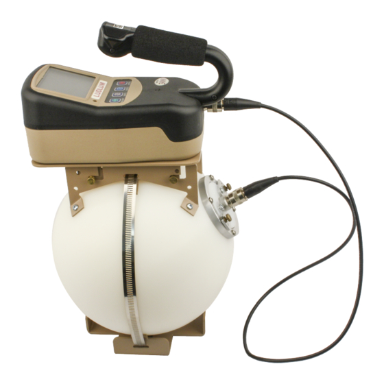
2.11. DOSE MODE OPERATION Figure 2.18: DOSE Mode Operation Display October 2022... - Page 41 3He proportional detector, 1.6 cm diameter x 2.5 cm thick (0.6 x 1.0 in.), surrounded by 19.6 cm (7.7 in.) diameter high density polyethylene sphere Sensitivity: Model 3007i: typically 10 cpm per Sv/h (100 cpm per mrem/hr)( AmBe fast neutrons) Model 3007Bi: typically 4.5 cpm per Sv/h (45 cpm per mrem/hr)(...
-
Page 42: Specifications
Size: 41.1 x 23.1 x 25.1 cm (16.3 x 9.1 x 9.9 in.) (H x W x L) Weight: 8.3kg (18.3 lb) with batteries NOTE: Tested in a 100mR/hr field. Testing in a 100 R/hr field yielded higher than expected response for energies greater than 1 MeV, but still within 40% of true value. Ludlum Measurements, Inc. -
Page 43: Setup Mode
4.1 Setup Overview Your instrument has been shipped from Ludlum Measurements only after passing electronic checkout, a 24-hour burn-in process, and a careful calibration process. Calibration papers are supplied with each instrument shipped from Ludlum Measurements. -
Page 44: Setup Parameters
Dead Time Correction 2 Mantissa Dead Time Correction 2 e-12 Exponent Detector Current Overload Threshold Detector Adjustable 0 (continuous) Scaler Count Detector Active Area Channel 1 – Threshold 0.002 0.025 Channel 1 - Window (V) 0 (max value) Ludlum Measurements, Inc. - Page 45 4.2. SETUP PARAMETERS Model Model Internal Setting Setup Parameter 42-49 42-49B Detector Channel 1 - Efficiency Channel 1 - Loss of Count Alarm Time Channel 1 - Radiation n (Neutron) Icon (Gamma) Unit 1 - RATE / MAX 2.00 mRem/h 2.00 mR/h Alarm 1 Unit 1 - RATE / MAX...
-
Page 46: Entering Setup Mode
SETUP PROTECT: The Model 3007i parameters can be protected from unauthorized changes via the internal switch located on the Model 3007i circuit board. To change the switch, open the battery compartment and remove the batteries from the Model 3007i. Next, loosen the six pan-head screws that fasten the bottom cover. -
Page 47: Backlight/Setup Protect Dipswitch
4.3. ENTERING SETUP MODE The dipswitch has a plastic cover, which protects the switch during manufactur- ing. This plastic cover is left on the dipswitch after assembly and is not removed until the dipswitch is needed. If the plastic cover still remains on the dipswitch, please remove the cover before changing the switch settings. -
Page 48: Setup Mode Operation
Lumic 2.0 Calibration Software. 4.4 Setup Mode Operation Once the Model 3007i is in Setup mode, setup page selection will be displayed on the LCD. Short press the MODE or ON/AUD button to choose the Setup Page you are interested in. -
Page 49: Model 3007I List Of Parameters (In Order)
Value to 150 mR/h. Enter the Setup Menu. Use the MODE or ON/AUD buttons to advance to U-1. Press the UNIT button to enter the menu. In the Model 3007i , if the appropriate DETECTOR LED is not lit, short press the DETECTOR button to cycle through the detectors until the appropriate LED is lit.Press the MODE button to get to the third of the 14 menu... - Page 50 • Detector Active Area Page 5 - CH_1 • Channel 1 - Threshold • Channel 1 - Window • Channel 1 - Efficiency • Channel 1 - Loss of Count Alarm Time • Channel 1 - Icon Ludlum Measurements, Inc.
- Page 51 4.5. MODEL 3007I LIST OF PARAMETERS (IN ORDER) Page 6 - U-1 • Unit 1 - RATE/MAX Units and Minimum Display • Unit 1 - RATE/MAX Maximum Display • Unit 1 - RATE/MAX Alarm 1 • Unit 1 - RATE/MAX Alarm 2 •...
-
Page 52: Device
Use the MODE and ON/AUD buttons to scroll through the available parameter options. Auto Shutdown Time - Upon entry into Auto Shutdown Time, the parameter will be selected (flashing). • 00 - 12 (hours until auto shutdown where 0 is off) Ludlum Measurements, Inc. - Page 53 4.6. PAGE 1 - DEVICE Use the MODE and ON/AUD buttons to scroll through the parameter options. Auxiliary Comm - Upon entry into Auxiliary Comm, the parameter will be selected (flash- ing). • 00 - SLURM • 01 - LMI Direct •...
-
Page 54: Datalogging
Use the MODE and ON/AUD buttons to scroll through the available parameter options. Mode - Upon entry into Mode, the parameter will be selected (flashing) indicating the state of the parameter. • 01 (log data, uses the first Location ID) • 02 (log data, user selectable Location ID) Ludlum Measurements, Inc. -
Page 55: Configuration
To begin adjusting a device parameter, short press the MODE or ON/AUD to scroll through the available device parameters. In the Model 3007i , when the appropriate parameter is selected, short press DETECTOR to select the detector that needs the parameter adjusted.To begin, short press UNIT to begin modifying the parameter chosen. -
Page 56: Detector Operation Modes
• log (bar graphing as a log scale) Use the MODE and ON/AUD buttons to scroll through the available parameter options. Response Rate - Upon entry into Response Rate, the parameter will be selected (flashing) indicating the state of the parameter. Ludlum Measurements, Inc. - Page 57 4.8. PAGE 3 - CONFIGURATION • USr (user-defined time) • A-S (auto slow) • F-S (fixed slow at 22 seconds) • A-F (auto fast) • F-F (fixed fast at 4 seconds) Use the MODE and ON/AUD buttons to scroll through the available parameter options. Response Time - Upon entry into the user-defined Response Time, the parameter will be selected (flashing) indicating the state of the parameter.
-
Page 58: Calibration
To begin adjusting a calibration parameter, short press the MODE or ON/AUD to scroll through the available calibration parameters.If in the Model 3007i , when the appropriate parameter is selected, short press DETECTOR to select the detector that needs the parameter adjusted. - Page 59 4.9. PAGE 4 - CALIBRATION • Ones Place (0-9) • Tens Place (0-9) Use the UNIT button to select the appropriate parameter, and use the MODE and ON/AUD buttons to scroll through the parameter options. Dead Time Correction 1 - Upon entry into Dead Time Correction, one of the following pa- rameters will be selected (flashing).
- Page 60 To begin adjusting a channel parameter, short press the MODE or ON/AUD to scroll through the available channel parameters. In the Model 3007i , when the appropriate parameter is selected, short press DETECTOR to select the detector that needs the parameter adjusted.
-
Page 61: Channel 1
4.10. PAGE 5 - CHANNEL 1 Channel 1 - Threshold - Upon entry into Channel 1 Threshold, one of the following param- eters will be selected (flashing). • Rightmost Digit (0-9) • Middle Digit (0-9) • Leftmost Digit (0-9) • Multiplier (m) with all digits flashing (adjustable from x.xx m to xxx m) Use the UNIT button to select the appropriate parameter, and use the MODE and ON/AUD buttons to scroll through the parameter options. - Page 62 , , & n • • , , & n • , , & n • , , , & n • 0FF – No icon Use the MODE and ON/AUD buttons to scroll through the available parameter options. Ludlum Measurements, Inc.
-
Page 63: Unit 1
To begin adjusting a unit parameter, short press the MODE or ON/AUD to scroll through the available unit parameters. In the Model 3007i , when the appropriate parameter is selected, short press DETECTOR to select the detector that needs the parameter adjusted. To begin, short press UNIT to begin modifying the parameter chosen. - Page 64 Display, one of the following parameters will be selected (flashing). Note: Select Unit first before selecting multiplier. • Multiplier with all digits flashing (adjustable from x.xx to xxx M depending on unit selected) • Unit (off, d, dpm, Bq, Bq/cm², c, cps, cpm, Rem, Rem/h, R, R/h, Sv, Sv/h) Ludlum Measurements, Inc.
- Page 65 4.11. PAGE 6 - UNIT 1 Use the UNIT button to select the appropriate parameter, and use the MODE and ON/AUD buttons to scroll through the parameter options. Unit 1 - COUNT Alarm 1 - Upon entry into Unit 1 Count Alarm 1, one of the following pa- rameters will be selected (flashing).
- Page 66 Use the UNIT button to select the appropriate parameter, and use the MODE and ON/AUD buttons to scroll through the parameter options. Unit 1 - DOSE Alarm 3 - Upon entry into Unit 1 Dose Alarm 3, one of the following parame- ters will be selected (flashing). Ludlum Measurements, Inc.
-
Page 67: Unit 2
To begin adjusting a unit parameter, short press the MODE or ON/AUD to scroll through the available unit parameters. If in the Model 3007i , when the appropriate parameter is selected, short press DETECTOR to select the detector that needs the parameter adjusted. - Page 68 Use the UNIT button to select the appropriate parameter, and use the MODE and ON/AUD buttons to scroll through the parameter options. Unit 2 - RATE/MAX Alarm 3 - Upon entry into Unit 2 RATE/MAX Alarm 3, one of the following parameters will be selected (flashing). Ludlum Measurements, Inc.
- Page 69 4.12. PAGE 7 - UNIT 2 • Rightmost Digit (0-9) • Middle Digit (0-9) • Leftmost Digit (0-9) • Multiplier with all digits flashing (adjustable from x.xx to xxx M depending on unit selected) Use the UNIT button to select the appropriate parameter, and use the MODE and ON/AUD buttons to scroll through the parameter options.
- Page 70 Unit 2 - DOSE Alarm 1 - Upon entry into Unit 2 Dose Alarm 1, one of the following parame- ters will be selected (flashing). • Rightmost Digit (0-9) • Middle Digit (0-9) • Leftmost Digit (0-9) • Multiplier with all digits flashing (adjustable from x.xx to xxx M depending on unit selected) Ludlum Measurements, Inc.
- Page 71 4.12. PAGE 7 - UNIT 2 Use the UNIT button to select the appropriate parameter, and use the MODE and ON/AUD buttons to scroll through the parameter options. Unit 2 - DOSE Alarm 2 - Upon entry into Unit 2 Dose Alarm 2, one of the following parame- ters will be selected (flashing).
-
Page 72: Reset (Warning!!!)
This reset is password protected, and the password will only be provided by the factory should it be required. Ludlum Measurements, Inc. -
Page 73: Datalogging
ATALOGGING The datalogging feature of the Model 3007i accessible through the use of the optional Lumic Datalogger software kit, allows the user to log radiation readings with the use of a handle- mounted LOG button. Data can be logged in any of the Model 3007i’s operational modes (RATE, MAX, and COUNT). -
Page 74: Datalogging Operation - Mode 2
– For a continuous Scaler count (Scaler time is 0), the LOG button is enabled at all times. • The LCD display will show a possible Location ID Table index for the user. The index will be auto-incremented from the previously used index. Ludlum Measurements, Inc. -
Page 75: Datalogging Operation - Mode 3
5.3. DATALOGGING OPERATION – MODE 3 Figure 5.2: Displaying Datalog Location ID Table Index of 36 • The number will be blinking, indicating a changeable value. The user may then enter the preferred Location ID Table index by a short press of the MODE (to increment the value) or ON/AUD (to decrement the value) buttons as in Setup mode. -
Page 76: Format
• Mode (1 Byte) • Detector Number (1 Byte) • Status (1 Byte) • Reserved (2 Bytes) • Elapsed Count Time in seconds (4 Bytes) • Scaler Count Time in seconds (4 Bytes) • Location ID (32 Bytes) Ludlum Measurements, Inc. -
Page 77: Software
OFTWARE 6.1 Connecting to Lumic 2.0 Calibration/Configuration Software The optional Ludlum Lumic 2 Calibration/Configuration software is sent with a standard two-meter cable. (A five-meter cable can be provided if requested. However, any cable longer than two meters may have issues with some USB hubs and computers, typically lap- tops.) To connect an instrument to the computer, please connect one end of the USB cable to the instrument first, and then the other end to the computer. -
Page 79: Advanced Features
DVANCED EATURES 7.1 Dead Time Correction All pulse counting detectors have a “dead time” in which the detector is unable to register another event. In relatively low fields this is not an issue. However, as the field strength approaches the high end of the detector’s range, dead time causes the pulse rate to become non-linear with respect to the real radiation field. -
Page 80: R To Sv Conversion
However, if calibration is required (due to board rework, etc.) the calibration settings are available in Lumic Calibra- tion software. 7.6 Other Device Data The following parameters on the instrument allow recording import device information within the device: Ludlum Measurements, Inc. -
Page 81: Battery Life
7.7. BATTERY LIFE Firmware Version: This is a read-only presentation of the firmware version. With a firmware version of F.x.y.zzzz, the F.x.y will show up on the device screen during the power-on sequence and signifies the released version. Device – Model Name: This should match the model name on the front face of the instrument. -
Page 83: Safety Considerations
Not certified for use in an explosive atmosphere 8.2 Warning Markings and Symbols The Model 3007i Survey meter is marked with the following symbols: CAUTION (per ISO 3864, No. B.3.1): designates hazardous live voltage and risk of electric shock. During normal use, internal components are hazardous live. -
Page 84: Cleaning And Maintenance Precautions
Ludlum Mea- surements, Inc. 8.3 Cleaning and Maintenance Precautions The Model 3007i may be cleaned externally with a damp cloth, using only water as the wet- ting agent. Observe the following precautions when cleaning or performing maintenance on the instru- ment: •... -
Page 85: Revision History
EVISION ISTORY This section of the manual will be updated with each revision of the Model 3007i in order to document changes over time. Ludlum Measurements’ policy is to provide free software upgrades to instruments for the life of the instrument. -
Page 87: Recycling
To this end, Ludlum Measurements, Inc. strives to supply the consumer of its goods with information regarding reuse and recycling of the many different types of materials used in its products. -
Page 89: Options
It allows administrators to adjust device datalogging parameters. Headphone Option (part # 4498-555): This provides the Model 3000 series of instruments with a jack and circuitry required for a standard headphone plug. Ludlum Measurements also offers mono/stereo headphones with volume control. -
Page 91: Standard Parts List
TANDARD ARTS Part Description Part Number Model 3007i Neutron Dose Survey Meter 48-4443 Model 3007Bi Neutron Dose Survey Meter 48-4443B Model 42-49 Detector and Moderator 47-4059 Model 42-49B Detector and Moderator 47-4308 Model 3007/3003 Sphere Assembly 4519-197 Model 3003 Main Board 5519-812 LCD 82 mm x 61.64 mm... -
Page 93: A Auxiliary Communications
UXILIARY OMMUNICATIONS A.1 AuxComm Overview AuxComm, short for Auxiliary Communications, is a feature included on certain Ludlum in- struments. An AuxComm port allows the instrument to expand its capabilities with a variety of external devices through a standard serial interface. A.2 Requirements In order to take advantage of the AuxComm functionality, you will need the following: •... -
Page 94: Auxcomm Usage - Pairing
4. Use 2-second Enable hot key to turn on WiFi. 5. Select “Scan” in App/Software. 6. When instrument is found by mobile device, select device in list and then “Pair.” 7. Enter PIN in App/Software from Step 2. Ludlum Measurements, Inc. - Page 95 A.3. USAGE Figure A.1: Example – Device Selection Figure A.2: Example – Pairing In Lumic Linker App (iOS) Figure A.3: Example – Model 3000 series Figure A.4: Example – Entering PIN In Found in Lumic Linker App (iOS) Lumic Linker App (iOS) October 2022...
-
Page 96: Settings
Raw Count: Mode that automatically transmits raw, uncorrected counts. The count interval is based on the AuxComm Auto Mode Interval variable (see A.4.6). The output value is the cumulative counts that occurred in the previous interval on all enabled channels. Ludlum Measurements, Inc. -
Page 97: Auxcomm Setting - Off Time
A.4. SETTINGS CPM: Mode that automatically transmits the CPM (counts per minute) for the external de- tector no matter what detector or mode is currently being displayed. The count interval is based on the AuxComm Auto Mode Interval variable (see A.4.6). Display: Mode that automatically transmits the numeric value as well as units prefix, units, and units suffix for the currently displayed screen. - Page 98 This setting controls the number of seconds for each transmitted value in automatic stream modes. The table below shows valid settings. Table A.6: AuxComm Auto Mode Interval Setting Description As fast as possible (1/4 second on Model 3000 series) 1-255 n-Seconds Ludlum Measurements, Inc.
Need help?
Do you have a question about the 3007i and is the answer not in the manual?
Questions and answers