
Related Manuals for Ludlum Measurements 3005


Summary of Contents for Ludlum Measurements 3005
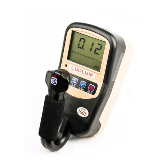
- Page 1 Model 3005 Digital Survey Meter with Internal Detector Ludlum Measurements December 2021 Serial Number: 25009185 and Succeeding Firmware: n42.4810 and Higher...
- Page 3 Model 3005 Digital Survey Meter with Internal Detector Ludlum Measurements December 2021 Serial Number: 25009185 and Succeeding Firmware: n42.4810 and Higher...
- Page 5 STATEMENT OF WARRANTY Ludlum Measurements, Inc. warrants the products covered in this manual to be free of de- fects due to workmanship, material, and design for a period of twelve months from the date of delivery. The calibration of a product is warranted to be within its specified accuracy lim- its at the time of shipment.
-
Page 10: Table Of Contents
Setup Mode Operation ....... . . 31 Model 3005 List of Parameters (in order) ..... . . 32 Setup Page 1 . - Page 11 A Energy Response A.1 Model 3005 Energy Response ......67 Ludlum Measurements, Inc.
-
Page 12: List Of Figures
A.1 Model 3005 Exposure ........ -
Page 14: List Of Tables
IST OF ABLES COUNT Mode Units and Result ......23 Setup Parameters ........29 Primary Units and Multipliers . -
Page 16: Introduction
The Model 3005 is an ergonomic, lightweight instrument which can be used for measure- ments of gamma radiation levels up to 50.0 mSv/h (5.00 R/hr). The Model 3005 features the ability to measure radiation in count rate, exposure rate/dose, activity rate, time-averaged rates, and scaler counts. - Page 17 It is located near the left handle base. If a headphone jack is not in use, the Model 3005 may optionally be provided with an RS- 232 serial output for connection to PC or other electronic device. For more advanced use:...
-
Page 18: Getting Started
Check individual item serial numbers and ensure calibration certificates match between instruments and de- tectors (if applicable). The Model 3005 serial number is located on a label on the front side of the unit. -
Page 19: Instrument Operational Test
Instead, use the following table to determine which main processor board is installed in the instrument: • 1 tick - 5498-612 • 2 ticks - 5519-091 • 3 ticks - 5519-779 Ludlum Measurements, Inc. -
Page 20: Battery Voltage Display
2.3. INSTRUMENT OPERATIONAL TEST The instrument then displays the battery voltage. Please see Figure below. Figure 2.3: Battery Voltage Display The instrument then displays the number of stored records if datalogging is enabled. Please refer to the figure below. Figure 2.4: Startup Display Showing 189 Stored Data Records The instrument will then move to normal operation, displaying the current rate for the Pri- mary units (factory default: mR/h). -
Page 21: Sigma Audio
fixed tone audio and a steady ALARM icon when a predetermined fixed alarm level is exceeded. 2.5 Detector Failure Diagnostics Note that the Model 3005 has its own diagnostic tests to ensure that the detector is function- ing correctly. 2.5.1 Detector Loss of Count If the detector stops detecting radiation for a settable number of seconds, the Model 3005 will flash the minimum display value to indicate which units have been affected by the loss... -
Page 22: Detector Over Range
Figure 2.6: Detector Over Range (Display Will Flash) 2.5.3 Detector Overload As another diagnostic test, the Model 3005 monitors the HV supply’s detector current. A cur- rent overload threshold can be set via Setup Mode or Lumic Software. (A setting of 0 disables this alarm.) In general, this alarm setting can be used to detect when there is some detec-... -
Page 23: Instrument Use And Controls
With four front-panel buttons and one handle button (as seen in front-panel drawing in front of manual), the Ludlum Model 3005 offers many features in a small package. Each button may be pressed and held for a predetermined length of time, signified by instrument beeps, to access unique instrument features. -
Page 24: Units Button
2.6. INSTRUMENT USE AND CONTROLS • During normal operation, it will acknowledge/silence alarms in any mode of opera- tion. • Change Log Location selected position (If data logging mode 2 is enabled). • Will move selection position in the device menu. Long Press (press and release after one beep): •... -
Page 25: Audio Button
• Device Menu: When viewing the detector current overload set point, this will switch the display between the live current reading and the set point value. 2.6.4 MODE Button: The Mode button’s primary function is to switch between available enabled modes. Short Press (press and release before one beep): Ludlum Measurements, Inc. -
Page 26: Log Button
2.6. INSTRUMENT USE AND CONTROLS • During instrument initialization and within 4 seconds after the power-up screen, three short presses of the MODE button will place the instrument into setup mode. Once the instrument is displaying normal operation, and 4 seconds have passed, the button can be used to advance to the next available mode. -
Page 27: Rate Mode Operation
If other operational modes are available, a short press of the MODE button will move to the next available operational mode. By default, a short press of the LOG button, if datalogging is enabled, will log the currently displayed rate. Figure 2.8: RATE Mode Displaying Background Radiation Rate Ludlum Measurements, Inc. -
Page 28: Max Mode Operation
2.8. MAX MODE OPERATION 2.8 MAX Mode Operation While in MAX mode, the highest detected count rate (since MAX mode was selected) is dis- played. The word MAX will be displayed when in MAX mode. A short press of the UNITS button will switch the displayed value between the Primary and Secondary Units. - Page 29 Other choices are to have count mode units of R/h or Sv/h, in which case the COUNT mode result is an averaged exposure or dose rate. But if count mode units of R or Sv are chosen, the Ludlum Measurements, Inc.
-
Page 30: Count Mode Units And Result
2.9. COUNT MODE OPERATION result is shown in accumulated exposure or accumulated dose over the chosen count time. The following tables lists the possibilities: UNITS RESULT counts per count time disintegrations per count time cpm, cps count rate averaged over the count time dpm, Bq disintegration rate, averaged over the count time R/h, Sv/h... - Page 31 • If other operational modes are available, a short press of the MODE button will move to the next available operational mode. • By default, a short press of the LOG button will log the current display. Figure 2.10: COUNT Mode Displaying COUNT Timer of 5 Minutes, 30 Seconds Ludlum Measurements, Inc.
-
Page 32: Specifications
Energy Response: 60 keV to 3 MeV (±25%) Detector Range: • 3005 (48-4231) 0.001 to 50 mSv/h (0.1 to 5000 mR/hr) • 3005/3 (48-4281) 0.001 to 250 mSv/h (0.1 to 25,000 mR/hr) • 3005/4 (48-4259) 0.001 to 500 mSv/h (0.1 to 50,000 mR/hr) - Page 33 Environmental Rating: NEMA (National Electrical Manufacturers Association) rating of 5 or IP (Ingress Protection) rating of 53 Size: 16.5 x 11.4 x 21.6 cm (6.5 x 4.5 x 8.5 in.) (H x W x L) Weight: 1.06 kg (2.3 lb) Ludlum Measurements, Inc.
-
Page 34: Setup Mode
4.1 Setup Overview Your instrument has been shipped from Ludlum Measurements only after passing electronic checkout, a 24-hour burn-in process, and a careful calibration process. Calibration papers are supplied with each instrument shipped from Ludlum Measurements. -
Page 35: Setup Parameters
2.00 kcpm Mode Alarm 1 Unit 2 - RATE/ MAX P3-4 5.00 kcpm Mode Alarm 2 Unit 2 - Count Units and P3-5 000 c Minimum Display Unit 2 - Count Units P3-6 000 c Alarm 1 Ludlum Measurements, Inc. -
Page 36: Entering Setup Mode
Table 4.1: Setup Parameters 4.3 Entering Setup Mode To enter Setup Mode, power down the Model 3005 then turn the unit back ON. When the instrument has begun normal operation, three short presses of the MODE button will place the instrument into Setup mode. - Page 37 CHAPTER 4. SETUP MODE SETUP PROTECT: By default, the Model 3005 is shipped with DIP Switch 2 in the OFF (back) position and all available Model 3005 parameters may be modified in Setup mode. To pro- tected the Model 3005 from changes in Setup mode, open the instrument, by removing the six screws on the bottom of the can, and slide DIP Switch 2 (the rightmost switch) to the ON (forward) position to activate Setup Protect Mode.
-
Page 38: Setup Mode Operation
4.4. SETUP MODE OPERATION 4.4 Setup Mode Operation Once the Model 3005 is in Setup mode, setup page selection will be displayed on the LCD and the Page number will be blinking indicating it as the selected item. The number of available parameters per Setup Page will be displayed using the graph where the number of segments indicates the number of parameters. -
Page 39: Model 3005 List Of Parameters (In Order)
• Press and hold the UNIT button until the instrument returns to normal operation. The list below shows the setup pages and the parameters in order, on each page. 4.5 Model 3005 List of Parameters (in order) Page 1 • Calibration Constant Mantissa •... - Page 40 4.5. MODEL 3005 LIST OF PARAMETERS (IN ORDER) • Primary COUNT Units and Minimum Display • Primary COUNT Mode Alarm 1 • Primary COUNT Mode Alarm 2 Page 3 • Secondary Units and Minimum Display • Secondary Units Maximum Display •...
-
Page 41: Setup
• Hundreds Place (0-9) Dead Time Correction 2 Mantissa - A short press of ON/OFF to select the value to adjust, and MODE to adjust the value. Available values are: • Ones Place (0-9) • Tens Place (0-9) Ludlum Measurements, Inc. - Page 42 Model 3005 display. But if the user desires to have the Model 3005 show results in terms of dpm/100 cm2, the user could manipulate the efficiency to produce this result by multiplying the efficiency times the ratio of the detector area to 100 cm2.
- Page 43 (flashing). Short press the ON/OFF to select the value to adjust, and MODE to adjust the value. Available values are: • Ones Place (0-9) • Tens Place (0-9) • Hundreds Place (0-9) Ludlum Measurements, Inc.
-
Page 44: Setup
4.7. SETUP PAGE 2 4.7 Setup Page 2 Primary RATE/MAX Units and Minimum Display - A short press of the ON/OFF to select the value to adjust, and MODE to adjust the value. Available values are: • Number of Decimal Places (0, 1, or 2) •... -
Page 45: Primary Unit Multipliers
MODE to adjust the value. Units will be the same as selected earlier with Primary Count Units. The ALARM LCD Segment will flash to indicate Alarm 1. Set this Alarm to 000 to disable. Available values are: • Ones Place (0-9) • Tens Place (0-9) • Hundreds Place (0-9) Ludlum Measurements, Inc. -
Page 46: Setup
4.8. SETUP PAGE 3 • Number of Decimal Places (0, 1, or 2) • Range (k on/off for cpm, cps, dpm, Bq; , m or none for R/h and Sv/h) If the Primary Count Units has changed to a value other than that used to pre- viously set this Alarm Point, the Alarm Point will be reset to 000. - Page 47 • Range (k on/off for cpm, cps, dpm, Bq; , m or none for R/h and Sv/h) If the Secondary Units has changed to a value other than that used to previously set this Alarm Point, the Alarm Point will be reset to 000. Ludlum Measurements, Inc.
-
Page 48: Secondary Unit Multipliers
4.8. SETUP PAGE 3 Secondary Count Units and Minimum Display - A short press of ON/OFF to select the value to adjust, and MODE to adjust the value. Available vallues are: • Number of Decimal Places (0, 1, or 2) •... -
Page 49: Setup
Setting the Response Time to a fixed value is useful primarily when per- forming surveys to a fixed MDA (Minimum Detectable Activity) level. Setting the Response Time to 0 will enable the Auto-Response mode for the Model 3005 (see the next parameter). Available values for the Response Time (in seconds) are: •... - Page 50 4.9. SETUP PAGE 4 • 1 - RATE and MAX Modes only • 2 - RATE AND COUNT Modes only • 3 - RATE Mode only Count Time - A short press of ON/OFF to select the value to be adjusted, and MODE to adjust the value.
-
Page 51: Setup
Hour - Displays the hour of the Real Time Clock. Valid values are 0 - 23. Minute - Displays the minutes of the Real Time Clock. Valid values are 00 - 59. Seconds - Displays the seconds of the Real Time Clock. Valid values are 00 - 59. Ludlum Measurements, Inc. -
Page 52: Datalogging
The datalogging feature of the Model 3005 allows the user to log radiation readings with the use of a handle-mounted LOG button. Data can be logged in any of the Model 3005’s oper- ational modes (RATE, MAX, and COUNT). Up to 1000 data points can be taken and stored internally. -
Page 53: Datalogging Operation - Mode 2
Mode 1. • The LCD display will show a possible Location ID Table index for the user. The index will be auto-incremented from the previously used index. Figure 5.2: Displaying Datalog Location ID Table Index of 36 Ludlum Measurements, Inc. -
Page 54: Datalogging Operation - Mode 3
5.3. DATALOGGING OPERATION – MODE 3 • The number will be blinking, indicating a changeable value. The user may then enter the preferred Location ID Table index by a short press of the MODE (to increment the value) as in Setup mode. •... -
Page 55: Data Log Operation
• Mode (1 Byte) • Detector Number (1 Byte) • Status (1 Byte) • Reserved (2 Bytes) • Elapsed Count Time in seconds (4 Bytes) • Scaler Count Time in seconds (4 Bytes) • Location ID (32 Bytes) Ludlum Measurements, Inc. -
Page 56: Software
OFTWARE 6.1 Connecting to Software The Model 3005 software is sent with a standard two-meter cable. (A five-meter cable can be provided if requested. However, any cable longer than two meters may have issues with some USB hubs and computers, typically laptops.) To connect an instrument to the computer, please connect one end of the USB cable to the instrument first, and then the other end to the computer. -
Page 58: Advanced Features
DVANCED EATURES 7.1 Dead Time Correction All pulse counting detectors have a “dead time” in which the detector is unable to register another event. In relatively low fields this is not an issue. However, as the field strength approaches the high end of the detector’s range, dead time causes the pulse rate to become non-linear with respect to the real radiation field. -
Page 59: R To Sv Conversion
Firmware Version: This is a read-only presentation of the firmware version. With a firmware version of F.x.y.zzzz, the F.x.y will show up on the device screen during the power-on sequence and signifies the released version. Ludlum Measurements, Inc. -
Page 60: Battery Life
7.7. BATTERY LIFE Device – Model Name: This should match the model name on the front face of the instrument. Device – Serial Number: This should match the serial number of the instrument. Detector – Model: This can store the model of the detectors the instrument was cali- brated for. -
Page 61: Cps Offset
fixed value, which must be configured while the instrument is connected to the Lumic Calibration 2.0 software and which is stored in the instrument and reused each time the instrument is powered on. By default, CPS Offset is 0 and no count subtraction is performed. Ludlum Measurements, Inc. -
Page 62: Safety Considerations
Not certified for use in an explosive atmosphere 8.2 Warning Markings and Symbols The Model 3005 Survey meter is marked with the following symbols: CAUTION (per ISO 3864, No. B.3.1): designates hazardous live voltage and risk of electric shock. During normal use, internal components are hazardous live. -
Page 63: Cleaning And Maintenance Precautions
Ludlum Mea- surements, Inc. 8.3 Cleaning and Maintenance Precautions The Model 3005 may be cleaned externally with a damp cloth, using only water as the wetting agent. Observe the following precautions when cleaning or performing maintenance on the instru- ment: •... -
Page 64: Revision History
EVISION ISTORY This section of the manual will be updated with each revision of the Model 3005 in order to document changes over time. Ludlum Measurements’ policy is to provide for free, the latest firmware release for an instrument for the life of that instrument. - Page 65 COUNT Mode Operation to explain predefined count times and proper operation. In Chap- ter 3: Specifications changed Detector from "version dependent, internal energy-compensated GM for Models 3005, 3005/3, and 3005/4" to "internal energy-compensated GM," changed Energy Range to Energy Response and in Detector Range added information for the three different 3005 versions, added "two adjustable"...
- Page 66 Specifications with Section 5.4 Data Log Operation and Section 5.5 Format, also Datalogging is no longer considered optional for the 3005. In Chapter 6: Software, deleted the Extended Features section. In Chapter 7: Advanced Features on page 53, added 7.7 Battery Life, 7.9 Button Mapping, and 7.10 CPS Offset.
-
Page 68: Recycling
To this end, Ludlum Measurements, Inc. strives to supply the consumer of its goods with information regarding reuse and recycling of the many different types of materials used in its products. -
Page 70: Options
It allows administrators to adjust device datalogging parameters. Headphone Option (part # 4498-555): This provides the Model 3000 series of instruments with a jack and circuitry required for a standard headphone plug. Ludlum Measurements also offers mono/stereo headphones with volume control. -
Page 72: Standard Parts List
TANDARD ARTS Part Description Part Number Model 3005 Digital Survey Meter 48-4231 Model 3019 Main Board 5519-091 Model 3000 Bezel Assembly 4498-412 Model 3000 Main Keypad Membrane Switch 7498-414 Model 3019 Handle Assembly 4498-607 Model 3000 Battery Holder Modified 7498-458... -
Page 74: A Energy Response
NERGY ESPONSE A.1 Model 3005 Energy Response Figure A.1: Model 3005 Exposure Figure A.2: Model 3005 Ambient Dose...
Need help?
Do you have a question about the 3005 and is the answer not in the manual?
Questions and answers