
Related Manuals for Ludlum Measurements 3-IS


Summary of Contents for Ludlum Measurements 3-IS
- Page 1 LUDLUM MODEL 3-IS AND 3-IS-1 INTRINSICALLY SAFE SURVEY METER October 2010 Serial Number 239605 and Succeeding Serial Number...
- Page 2 Warning – A special cable(Part Number 8303-764 (-xx), where xx represents a length in feet) is supplied with the Model 3-IS. If replacement is needed, ensure that the same type is used. This cable is identified by type “C” connectors with locking screws and a light-blue molded-rubber strain relief.
- Page 4 RETURN OF GOODS TO MANUFACTURER If equipment needs to be returned to Ludlum Measurements, Inc. for repair or calibration, please send to the address below. All shipments should include documentation containing return shipping address, customer name, telephone number, description of service requested, and all other necessary information.
- Page 5 Model 3-IS & 3-IS-1 Technical Manual Ludlum Measurements, Inc. October, 2010...
- Page 6 Model 3-IS & 3-IS-1 Technical Manual Ludlum Measurements, Inc. October, 2010...
- Page 7 Model 3-IS & 3-IS-1 Technical Manual Ludlum Measurements, Inc. October, 2010...
-
Page 8: Table Of Contents
Model 3-IS & 3-IS-1 Technical Manual Table of Content Introduction Getting Started Unpacking and Repacking Battery Installation Connecting a Detector to the Instrument Battery Test Instrument Test Reading the Meter Face Dial Operational Check Specifications Identification of Controls and Functions... - Page 9 Model 3-IS & 3-IS-1 Technical Manual Troubleshooting Troubleshooting Electronics which utilize a G-M Detector or Scintillator Troubleshooting G-M Detectors Troubleshooting Scintillators Technical Theory of Operation Low Voltage Supply High Voltage Supply Detector Input Amplifier Discriminator Audio Scale Ranging Meter Drive...
-
Page 10: Introduction
AUD ON There are three Geiger-Mueller (GM) detectors which are qualified for use with the Model 3-IS. Additionally, two types of scintillation detector may be used. The qualified GM detectors operate at 900 volts. Operating voltage for the scintillation detectors is determined by using the plateau method outlined on page 6-4, or by using a detector-specific procedure. -
Page 11: Getting Started
Model 3-IS & 3-IS-1 Technical Manual Section 2 Section Getting Started Important: This instrument is designed to be INTRINSICALLY SAFE in Class I Division I Group A, B, C, and D Hazardous locations. Warning: Use only Duracell Procell PC1300 1.5V type “D” batteries. To reduce the risk of ignition of a flammable or explosive atmosphere, batteries must be changed only in a location known to be a non-hazardous area. -
Page 12: Unpacking And Repacking
(batteries, cable, etc.) and ensure that all of the items listed on the packing list are in the carton. Check individual item serial numbers and ensure calibration certificates match. The Model 3-IS serial number is located on the front panel below the battery compartment. Most Ludlum Measurements, Inc. detectors have a label on the base or body of the detector for model and serial number identification. -
Page 13: Connecting A Detector To The Instrument
Warning – A special cable(Part Number 8303-764 (-xx), where xx represents a length in feet) is supplied with the Model 3-IS. If replacement is needed, ensure that the same type is used. This cable is identified by type “C”... -
Page 14: Instrument Test
˝ position should respond approximately 5 times slower than the ˝ ˝ position. The detector cable (on the Model 3-IS only) can be a source of problems. Test the detector cable by bending or flexing either end of the cable and checking for an increase in the rate of counts detected. - Page 15 Model 3-IS & 3-IS-1 Technical Manual Section 2 The count rate scale reads 0-5K (kcpm or 1000’s of counts COUNTS MINUTE per minute) and has on the dial. BAT TEST If the needle is pointing as indicated below and the instrument range selection switch is on the ×0.1 scale multiple, then the reading is 3.5 kcpm (multiplied...
- Page 16 Model 3-IS & 3-IS-1 Technical Manual Section 2 If the needle is pointing as indicated below and the range selection switch is on the ×0.1 scale, then the reading is 0.1mR/hr. The same needle indications on successive ranges would be: ×1 = 1.0 mR/hr (or 1,000 µR/hr)
-
Page 17: Operational Check
Model 3-IS & 3-IS-1 Technical Manual Section 2 The same needle indication on successive ranges would be: ×1 = 4.2kcpm (or 4,200 cpm) ×10 = 42kcpm (or 42,000 cpm) ×100 = 420kcpm (or 420,000 cpm) If you use the mR/hr scales, then the readings would be: ×0.1 = 0.13 mR/hr... -
Page 18: Specifications
Model 3-IS & 3-IS-1 Technical Manual Section 3 Section Specifications : two cell batteries (Duracell Procell PC1300 1.5V alkaline) Power ˝ ˝ housed in a sealed externally accessible compartment. : typically greater than 2000 hours with the switch Battery Life... - Page 19 ˝C˝ connector and light blue molded rubber strain relief is provided with each instrument. Warning (Model 3-IS only): A special cable is supplied (Part Number 8303-764(-xx), where “ xx” represents a length in feet)with the Model 3- IS. If replacement is needed, ensure that the same type is used.
-
Page 20: Identification Of Controls And Functions
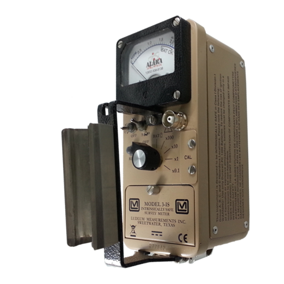
Typical meter dials are 0-2 mR/hr, 0-20 µSv/h, 0-5k cpm or combination of exposure rates (0-2 mR/hr or 0-20 µSv/h) and cpm and BAT TEST : (Model 3-IS only) Series “C”, used to connect the detector to the Connector instrument. - Page 21 Model 3-IS & 3-IS-1 Technical Manual Section 4 the higher the audio frequency. The audio should be turned when not required to reduce battery drain. Note: A low battery condition results in a steady audio tone regardless of the position of the switch.
-
Page 22: Safety Considerations
60 seconds before connecting or disconnecting the cable or detector. Warning! A special 39 inch cable is supplied with the Model 3-IS. If replacement is needed, ensure the same type is used. This cable is identified by type “C” connectors with locking screws and light- blue molded-rubber strain relief. -
Page 23: Warning Markings And Symbols
The operator or responsible body is cautioned that the protection provided by the equipment may be impaired if the equipment is used in a manner not specified by Ludlum Measurements, Inc. The Model 3-IS Survey Meter is marked with the following symbols: CAUTION, RISK OF ELECTRIC SHOCK (per ISO 3864, No. -
Page 24: Cleaning And Maintenance Precautions
Section 5 Cleaning and Maintenance Precautions The Model 3-IS may be cleaned externally with a damp cloth, using only water as the wetting agent. Do not immerse the instrument in any liquid. Observe the following precautions when cleaning or performing maintenance on the instrument: 1. -
Page 25: Calibration And Maintenance
Model 3-IS & 3-IS-1 Technical Manual Section 6 Section Calibration and Maintenance Calibration Calibration controls are located on the front of the instrument under the calibration cover. The controls may be adjusted with a 1/8-inch blade screwdriver. Note: Local procedures may supersede the following The instrument may be calibrated using exposure rate calibration or cpm calibration, (both methods are described below.) Unless otherwise specified,... -
Page 26: Exposure Rate Calibration
400 µR/hr point. Then switch the Pulser “multiplier” switch to the next lower setting, and adjust the appropriate calibration control on the Model 3-IS for the meter to read 40 µR/hr. CPM Calibration Connect the input of the instrument to a negative pulse generator, such as a Ludlum Model 500 Pulser. -
Page 27: Establishing An Operating Point
Check the 20% scale indication of the Model 3-IS by reducing the Pulser count rate by a factor of 4. The Model 3-IS should read within 10% of the actual pulse rate. Decrease the pulse rate of the Model 500 by one decade and turn the Model 3-IS range selector to the next lower range. - Page 28 Model 3-IS & 3-IS-1 Technical Manual Section 6 the discrimination level and are therefore not counted. The system gain is controlled by adjusting the HV (high voltage). Note: Measure the HV with a Ludlum Model 500 Pulser. If the Pulser...
-
Page 29: Maintenance
Maintenance Instrument maintenance consists of keeping the instrument clean and periodically checking the batteries and the calibration. The Model 3-IS instrument may be cleaned with a damp cloth (using only water as the wetting agent). Do not immerse instrument in any liquid. Observe the following precautions when cleaning: 1. - Page 30 Model 3-IS & 3-IS-1 Technical Manual Section 6 Note: Never store the instrument over 30 days without removing the batteries. Although this instrument will operate at very high ambient temperatures, battery seal failure may occur at temperatures as low as 100°F.
-
Page 31: Troubleshooting
Model 3-IS & 3-IS-1 Technical Manual Section 7 Section Troubleshooting ccasionally, you may encounter problems with your LMI instrument or detector that may be repaired or resolved in the field, saving turnaround time and expense in returning the instrument to us for repair. Toward that end, LMI electronics technicians offer the following tips for troubleshooting the most common problems. - Page 32 Model 3-IS & 3-IS-1 Technical Manual Section 7 SYMPTOM POSSIBLE SOLUTION No power (or meter Check battery contacts. Clean them does not reach with rough sandpaper or use an engraver to clean the tips. TEST BAT OK mark) (continued) Remove the can and check for loose or broken wires.
-
Page 33: Troubleshooting Gm Detectors
Model 3-IS & 3-IS-1 Technical Manual Section 7 SYMPTOM POSSIBLE SOLUTION Meter goes full-scale Remove the can and check for loose or “pegs out” or broken wires. (continued) Ensure that the instrument’s “can” is properly attached. When attached properly, the speaker will be located on the left side of the instrument. -
Page 34: Troubleshooting Scintillators
Model 3-IS & 3-IS-1 Technical Manual Section 7 3. If the input sensitivity is too low, the user could see some double-pulsing. 4. Wires to the tube may be broken or the crimped connector could have a loose wire. Troubleshooting Scintillators 1. -
Page 35: Technical Theory Of Operation
Model 3-IS & 3-IS-1 Technical Manual Section 8 Section Technical Theory of Operation Low Voltage Supply Battery voltage is coupled to U11 and associated components (a switching regulator) to provide 5 volts at pin 8 to power all logic circuits. A voltage divider (R27 and R32) located at pin 1 of U11 sets the end-of-battery–life... -
Page 36: Discriminator
Model 3-IS & 3-IS-1 Technical Manual Section 8 Discriminator Comparator U8 provides discrimination. The discriminator is set by a voltage divider (R21 and R23), coupled to pin 3 of U8. As the amplified pulses at pin 4 of U8 increase above the discriminator voltage, 5 volt negative pulses are produced at pin 1 of U8. -
Page 37: Recycling
To this end, Ludlum Measurements, Inc. strives to supply the consumer of its goods with information regarding reuse and recycling of the many different types of materials used in its products. -
Page 38: Parts List
Model 3-IS & 3-IS-1 Technical Manual Section 10 Section Parts List Reference Description Part Number Model 3-IS UNIT Completely Assembled Survey Meter Model 3-IS Survey Meter 48-3581 Main Board, BOARD Completely Assembled Drawing 464 × 355 Main Circuit Board 5464-355... - Page 39 Model 3-IS & 3-IS-1 Technical Manual Section 10 Reference Description Part Number MMBT3904LT1 05-5841 TRANSISTORS MMBT4403LT1 05-5842 U1-U3 MAX4542ESA 06-6453 INTEGRATED CIRCUITS U4-U5 CMXT3904 05-5888 CMXT3906 05-5890 MAX4541ESA 06-6452 MAX985EUK-T 06-6459 CD74HC4538M 06-6297 LMC7111BIM5X 06-6410 LT1304CS8-5 06-6434 MIC1557BM5 06-6457 LT1304CS8...
-
Page 40: Safety Board, Drawing 464 × 361
Model 3-IS & 3-IS-1 Technical Manual Section 10 Reference Description Part Number 2K, 1/8W, 1% 12-7926 R20-R21 100K, 1/8W, 1% 12-7834 1M, 1/8W, 1% 12-7844 2.49K, 1/8W, 1% 12-7999 14.7K, 1/8W, 1% 12-7068 200K, 1/4W, 1% 12-7992 100K, 1/4W, 1% 12-7834 68.1K, 1/8W, 1% 12-7881... -
Page 41: Wiring Diagram, Drawing 464 × 358
Model 3-IS & 3-IS-1 Technical Manual Section 10 Reference Description Part Number Wiring Diagram, Model 3-IS-1 Drawing 464 × 358 Detector Board 5408-267 1 MEG, 1/4W, 5% 10-7028 BOARD GM Tube- LND72611 01-5011 MISCELLANEOUS Meter 4363-188 25 ohm, 2.5W, 5% 12-7245 Ludlum Measurements, Inc. - Page 42 Model 3-IS & 3-IS-1 Technical Manual Section 11 Section Drawings MAIN CIRCUIT BOARD, Drawing 464 × 355 (3 sheets) MAIN CIRCUIT BOARD LAYOUT, Drawing 464 × 356 (2 sheets) SAFETY BOARD, Drawing 464 × 361 SAFETY BOARD LAYOUT, Drawing 464 × 362 CHASSIS WIRING DIAGRAM, Drawing 464 ×...
Need help?
Do you have a question about the 3-IS and is the answer not in the manual?
Questions and answers