
Related Manuals for Ludlum Measurements 3003


Summary of Contents for Ludlum Measurements 3003
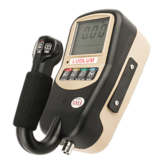
- Page 1 LUDLUM MODEL 3003 AND 3003i MULTI-DETECTOR SURVEY METER / SCA USER’S MANUAL September 2020 Firmware: F.2.0.1263 and Higher...
- Page 2 LUDLUM MODEL 3003 AND 3003i MULTI-DETECTOR SURVEY METER / SCA USER’S MANUAL September 2020 Firmware: F.2.0.1263 and Higher...
- Page 3 User’s Manual Model 3003 and 3003i Multi-Detector Survey Meter / SCA...
- Page 4 RETURN OF GOODS TO MANUFACTURER If equipment needs to be returned to Ludlum Measurements, Inc. for repair or calibration, please send to the address below. All shipments should include documentation containing return shipping address, customer name, telephone number, description of service requested, and all other necessary information.
-
Page 5: Table Of Contents
User’s Manual Model 3003 and 3003i Multi-Detector Survey Meter / SCA Table of Contents Introduction Getting Started Unpacking and Repacking Battery Installation Instrument Operational Test Sigma Audio Detector Failure Diagnostic Instrument Use and Controls RATE Mode Operation 2-12 MAX Mode Operation... - Page 6 User’s Manual Model 3003 and 3003i Multi-Detector Survey Meter / SCA Datalogging Operation – Mode 2 Datalogging Operation – Mode 3 Format Software Connecting to Software Advanced Features Dead Time Correction Units Software Calibration Tools Other Device Data Battery Life...
-
Page 8: Introduction
The Model 3003 and 3003i are ergonomic, lightweight instruments which can be used for radiation survey purposes. The Model 3003i version has all the features of the Model 3003 plus the addition of an internal detector for tracking user exposure rate or dose, but both instruments will hereafter be referred to as “3003.”... - Page 9 Lumic software. Using the Lumic software, the Model 3003 can be configured to allow changes to the alarms and/or count time even when in protect mode.
- Page 10 Model 3003 and 3003i Multi-Detector Survey Meter / SCA Section 1 If a headphone jack is not in use, the Model 3003 may optionally be provided with an RS-232 serial output for connection to PC or other electronic devices. For more advanced use: See Appendix A for information on our...
-
Page 11: Getting Started
Check individual item serial numbers and ensure calibration certificates match between instruments and detectors (if applicable). The Model 3003 serial number is located on a label on the front side of the unit. To return an instrument for repair or calibration, provide sufficient packing material to prevent damage during shipment. -
Page 12: Instrument Operational Test
Please refer to Figure 1 below. Figure 1: Startup Display for Model 3003 (All Segments Shown) The instrument then displays the current revision level of each board installed in the system: main board, internal detector high voltage board, and auxiliary communications board. - Page 13 Model 3003 and 3003i Multi-Detector Survey Meter / SCA Section 2 Next, the instrument displays the firmware version. Figure 3: Firmware Version Display The first character defines the firmware type, the second character defines the major version level, and the third character defines the revision level.
- Page 14 Model 3003 and 3003i Multi-Detector Survey Meter / SCA Section 2 The instrument then displays the number of stored records if datalogging is enabled. Figure 5: Startup Display Showing 189 Stored Data Records If the Sigma Audio option is selected, the unit will display a countdown from :08 to :01 (in seconds) as the unit measures background radiation levels.
-
Page 15: Sigma Audio
ALARM icon when a predetermined fixed alarm level is exceeded. Detector Failure Diagnostic Note that the Model 3003 has its own diagnostic tests to ensure that the detector is functioning correctly. The Model 3003 can detect when the radiation detector is malfunctioning and will flash the display to indicate a fault. - Page 16 Model 3003 and 3003i Multi-Detector Survey Meter / SCA Section 2 Figure 6: Detector Loss of Count Display (Display Will Also Flash) Detector Over Max If the detector exceeds the programmed maximum value for the given unit, the instrument flashes the maximum value for the currently selected units and the MAX icon as a warning.
-
Page 17: Instrument Use And Controls
OVERLOAD and ALARM icons, three dashes will be displayed in place of the numerical values and an alarm tone will sound. Once the detector current goes below the threshold, the Model 3003 will return to normal operation. Figure 9: Detector Overload Alarm (Display Will Also Flash) - Page 18 By default, the majority of functions are assigned to short presses of the buttons. ON/AUD button Used to power the Model 3003 ON and OFF and adjust the audio level (mute, low, medium, or high). Power On: Press for approximately one second and release (all ...
- Page 19 Model 3003 and 3003i Multi-Detector Survey Meter / SCA Section 2 Currently has no effect. DETECTOR button The Detector button’s primary function is to switch between available enabled detectors. Short Press (press and release the button after one beep) Used to select the active detector, as evidenced by the ...
- Page 20 Model 3003 and 3003i Multi-Detector Survey Meter / SCA Section 2 ACK/RST button Short Press (press and release the button after one beep) In all modes, the button is used to acknowledge (silence) alarms. In COUNT mode, if the count is initialized, the button will initiate the count without logging the results upon completion.
- Page 21 Model 3003 and 3003i Multi-Detector Survey Meter / SCA Section 2 Currently has no effect. Extra-Long Press (press and release the button after three beeps) In RATE, MAX, or DOSE mode, the button has no effect. In COUNT mode, it will: ...
-
Page 22: Rate Mode Operation
Model 3003 and 3003i Multi-Detector Survey Meter / SCA Section 2 RATE Mode Operation In RATE mode, the current count rate will be displayed. An extra-long press of the ACK/RST button will reset the averaged rate before releasing the button. The Reset feature must be enabled through Lumic Calibration software and will be disabled when Sigma Audio is enabled. -
Page 23: Max Mode Operation
Model 3003 and 3003i Multi-Detector Survey Meter / SCA Section 2 MAX Mode Operation While in MAX mode, the highest detected count rate (since MAX mode was selected) is displayed. The word MAX will be displayed when in MAX mode. -
Page 24: Count Mode Operation
Model 3003 and 3003i Multi-Detector Survey Meter / SCA Section 2 COUNT Mode Operation When entering COUNT Mode from another operational mode, the currently selected COUNT Unit will be displayed for approximately one second. The purpose of COUNT mode is to count for a predetermined amount of time, and to display the results on the display. - Page 25 Model 3003 and 3003i Multi-Detector Survey Meter / SCA Section 2 Dev Cnt Audio Mode will enable\disable click audio during a COUNT Off - always off On - always on W_Count - audio is only enabled during an active count Note: Sigma audio is disabled in Count Mode.
- Page 26 Model 3003 and 3003i Multi-Detector Survey Meter / SCA Section 2 In COUNT mode, operation depends on the current state of the Count Timer. When the Count Timer is Ready: The display will show the Count Time. A short press of the UNITS button will switch between the Primary and Secondary Count Units (and Tertiary if alpha/beta is enabled).
- Page 27 Model 3003 and 3003i Multi-Detector Survey Meter / SCA Section 2 If datalogging is enabled and logging the count results was previously requested, the results will be logged to the log buffer. A short press of the UNITS button will switch between the Primary and Secondary Count Units.
-
Page 28: Dose Mode Operation
Model 3003 and 3003i Multi-Detector Survey Meter / SCA Section 2 DOSE Mode Operation While in DOSE mode, the current accumulated dose will be shown. The icon INTG will be displayed when in DOSE mode. A short press of the UNITS button will switch the displayed value between the Primary and Secondary Units (Tertiary Units if the detector is configured for alpha/beta). -
Page 29: Specifications
Model 3003 and 3003i Multi-Detector Survey Meter / SCA Section 3 Section Specifications External Detector: may be Geiger-Mueller (GM), scintillator, proportional, or neutron; supports optional internal GM or scintillation detector Internal Detector (If installed): one energy-compensated GM tube Energy Response: within 25% of true value from 60 keV to 3 MeV... - Page 30 Model 3003 and 3003i Multi-Detector Survey Meter / SCA Section 3 UNITS – changes the units between count rate, dose/exposure, or disintegration DETECTOR – short press to change active detector to the next enabled detector MODE – short press alternates between available modes: RATE (count rate), MAX ( captures peak rate), COUNT ( user-selectable preset count time from 0 to 115.625 days) , and DOSE...
-
Page 31: Setup Mode
Ludlum Measurements. Recalibration should be accomplished after a predetermined calibration frequency (Ludlum Measurements, Inc. recommends no more than a one year interval), or when the operation of the instrument is suspect, or maintenance has been performed on the instrument. Recalibration is not normally required following instrument cleaning or battery replacement. -
Page 32: Setup Parameters
Model 3003 and 3003i Multi-Detector Survey Meter / SCA Section 4 Setup Parameters Model Model Alpha or Model Internal Setting Setup Parameter 133-6 44-2 Beta 42-31H Detector Multi-level Audio Backlight Threshold Auto Shutdown Time Auxiliary COM1 0 (disabled) Auxiliary COM2... - Page 33 Model 3003 and 3003i Multi-Detector Survey Meter / SCA Section 4 Model Model Alpha or Model Internal Setting Setup Parameter 133-6 44-2 Beta 42-31H Detector Dead Time Correction 1 36 e-6 10 e-6 5 e-6 5 e-6 80 e-6 Dead Time Correction 2...
- Page 34 Model 3003 and 3003i Multi-Detector Survey Meter / SCA Section 4 Model Model Alpha or Model Internal Setting Setup Parameter 133-6 44-2 Beta 42-31H Detector Unit 1 - COUNT 0.00 µR 000 c 0.00 µSv 0.00 µR Units and Minimum...
- Page 35 Model 3003 and 3003i Multi-Detector Survey Meter / SCA Section 4 Model Model Alpha or Model Internal Setting Setup Parameter 133-6 44-2 Beta 42-31H Detector Unit 2 - DOSE 0 (disabled) Units and Minimum Display Unit 2 - DOSE 0 (disabled)
-
Page 36: Entering Setup Mode
If the menu is not exited properly, any changes made will not be saved. SETUP PROTECT: The Model 3003 parameters can be protected from unauthorized changes via the internal switch located on the Model 3003 circuit board. To change the switch, open the battery compartment and remove the Ludlum Measurements, Inc. - Page 37 Model 3003 and 3003i Multi-Detector Survey Meter / SCA Section 4 batteries from the Model 3003. Next, loosen the six pan head screws that fasten the bottom cover. Gently remove the bottom cover of the instrument. The DIP (dual in-line position) switch should now be visible in the center of the circuit board.
-
Page 38: Setup Mode Operation
Lumic Calibration Software. Setup Mode Operation Once the Model 3003 is in Setup mode, setup page selection will be displayed on the LCD. Short press the PRG or RST button to choose the Setup Page you are interested in. - Page 39 Model 3003 and 3003i Multi-Detector Survey Meter / SCA Section 4 Extra-long-pressing the LOG button, no matter what parameter is shown, will first return the user back to the Page Selection screen and then save and exit if held for approximately 5 seconds in total.
-
Page 40: Model 3003 List Of Parameters (In Order)
Model 3003 and 3003i Multi-Detector Survey Meter / SCA Section 4 Press the LOG button for 2 seconds to exit Setup. The list below shows the four setup pages and the parameters in order, on each page. Model 3003 List of Parameters (in order) Page 1 - dev ... - Page 41 Model 3003 and 3003i Multi-Detector Survey Meter / SCA Section 4 Page 4 - CAL High Voltage Setpoint Calibration Constant Mantissa Calibration Constant Exponent Dead Time Correction 1 Dead Time Correction 2 Mantissa Dead Time Correction 2 Exponent ...
-
Page 42: Page 1 - Device
Model 3003 and 3003i Multi-Detector Survey Meter / SCA Section 4 Unit 1 - DOSE Alarm 3 Unit 1 - Channel Page 9 - U-3 (if supported) Unit 3 - RATE/MAX Units and Minimum Display Unit 3 - RATE/MAX Maximum Display ... - Page 43 Model 3003 and 3003i Multi-Detector Survey Meter / SCA Section 4 lo (backlight low) hi (backlight high) aut (backlight auto adjusts to light conditions) Use the PRG and ACK/RST buttons to scroll through the available parameter options.
-
Page 44: Page 2 - Datalogging
Model 3003 and 3003i Multi-Detector Survey Meter / SCA Section 4 Thousands place is assumed to be two (for 2000). Use the LOG button to select the appropriate parameter and use the PRG and ACK/RST buttons to scroll through the parameter options. -
Page 45: Page 3 - Configuration
Model 3003 and 3003i Multi-Detector Survey Meter / SCA Section 4 03 (auto log data, user-defined log interval and Location ID) Use the PRG and ACK/RST buttons to scroll through the available parameter options. Location ID - Upon entry into Location ID, the parameter will be selected (flashing) indicating the state of the parameter. - Page 46 Model 3003 and 3003i Multi-Detector Survey Meter / SCA Section 4 Figure 17: Detector Operation Modes Each mode is represented on the LCD screen as follows: r - rate mode (always enabled) c - count mode (scaler) MAX - MAX mode ...
-
Page 47: Page 4 - Calibration
Model 3003 and 3003i Multi-Detector Survey Meter / SCA Section 4 F-F (fixed fast at 4 seconds) Use the PRG and ACK/RST buttons to scroll through the available parameter options. Response Time - Upon entry into the user-defined Response Time, the parameter will be selected (flashing) indicating the state of the parameter. - Page 48 Model 3003 and 3003i Multi-Detector Survey Meter / SCA Section 4 High Voltage - Upon entry into High Voltage, one of the following parameters will be selected (flashing). Ones Place (0-9) Tens Place (0-9) Hundreds Place (0-9) ...
- Page 49 Model 3003 and 3003i Multi-Detector Survey Meter / SCA Section 4 Dead Time Correction 2 Mantissa - Upon entry into Dead Time Correction 2 Mantissa, one of the following parameters will be selected (flashing). Ones Place (0-9) Tens Place (0-9) ...
-
Page 50: Channel
Model 3003 and 3003i Multi-Detector Survey Meter / SCA Section 4 Detector Active Area - Upon entry into Detector Active Area, one of the following parameters will be selected (flashing). Rightmost Digit (0-9) Middle Digit (0-9) Leftmost digit (0-9) ... - Page 51 Model 3003 and 3003i Multi-Detector Survey Meter / SCA Section 4 Channel 1 – Efficiency (%) - Upon entry into Channel 1 Efficiency, one of the following parameters will be selected (flashing). Rightmost Digit (0-9) Middle Digit (0-9) ...
- Page 52 Model 3003 and 3003i Multi-Detector Survey Meter / SCA Section 4 the parameter adjusted. To begin, short press LOG to begin modifying the parameter chosen. Finally, extra-long pressing the LOG button will complete the modification. Channel 2 - Threshold - Upon entry into Channel 2 Threshold, one of the following parameters will be selected (flashing).
-
Page 53: Unit
Model 3003 and 3003i Multi-Detector Survey Meter / SCA Section 4 Hundreds digit (0-9) Use the LOG button to select the appropriate parameter and use the PRG and ACK/RST buttons to scroll through the parameter options. Channel 2 - Icon - Upon entry into Channel 2 Icon, one of the following parameters will be selected (flashing). - Page 54 Model 3003 and 3003i Multi-Detector Survey Meter / SCA Section 4 Unit 1 - RATE/MAX Maximum Display - Upon entry into Unit 1 RATE/MAX Units Maximum Display, one of the following parameters will be selected (flashing). Rightmost Digit (0-9) ...
- Page 55 Model 3003 and 3003i Multi-Detector Survey Meter / SCA Section 4 Multiplier with all digits flashing (adjustable from x.xx µ to xxx M depending on unit selected) Use the LOG button to select the appropriate parameter and use the PRG and ACK/RST buttons to scroll through the parameter options.
- Page 56 Model 3003 and 3003i Multi-Detector Survey Meter / SCA Section 4 Rightmost Digit (0-9) Middle Digit (0-9) Leftmost digit (0-9) Multiplier with all digits flashing (adjustable from x.xx µ to xxx M depending on unit selected) Use the LOG button to select the appropriate parameter and use the PRG and ACK/RST buttons to scroll through the parameter options.
-
Page 57: Unit
Model 3003 and 3003i Multi-Detector Survey Meter / SCA Section 4 Unit 1 - DOSE Alarm 3 - Upon entry into Unit 1 Dose Alarm 3, one of the following parameters will be selected (flashing). Rightmost Digit (0-9) Middle Digit (0-9) ... - Page 58 Model 3003 and 3003i Multi-Detector Survey Meter / SCA Section 4 Multiplier with all digits flashing (adjustable from x.xx µ to x.xx k) Unit (off, dpm, Bq, Bq/cm, cpm, cps, Rem/h, R/hr, Sv/h) Use the LOG button to select the appropriate parameter and use the PRG and ACK/RST buttons to scroll through the parameter options.
- Page 59 Model 3003 and 3003i Multi-Detector Survey Meter / SCA Section 4 Rightmost Digit (0-9) Middle Digit (0-9) Leftmost digit (0-9) Multiplier with all digits flashing (adjustable from x.xx µ to xxx M depending on unit selected) Use the LOG button to select the appropriate parameter and use the PRG and ACK/RST buttons to scroll through the parameter options.
- Page 60 Model 3003 and 3003i Multi-Detector Survey Meter / SCA Section 4 Use the LOG button to select the appropriate parameter and use the PRG and ACK/RST buttons to scroll through the parameter options. Unit 2 - COUNT Alarm 3 - Upon entry into Unit 2 Count Alarm 3, one of the following parameters will be selected (flashing).
-
Page 61: Unit 3 (If Supported)
Model 3003 and 3003i Multi-Detector Survey Meter / SCA Section 4 Multiplier with all digits flashing (adjustable from x.xx µ to xxx M depending on unit selected) Use the LOG button to select the appropriate parameter and use the PRG and ACK/RST buttons to scroll through the parameter options. - Page 62 Model 3003 and 3003i Multi-Detector Survey Meter / SCA Section 4 will be selected (flashing). Note: Select Unit first before setting other parameters. Rightmost Digit (0-9) Middle Digit (0-9) Leftmost digit (0-9) Multiplier with all digits flashing (adjustable from x.xx µ to x.xx k) ...
- Page 63 Model 3003 and 3003i Multi-Detector Survey Meter / SCA Section 4 Multiplier with all digits flashing (adjustable from x.xx µ to xxx M depending on unit selected) Use the LOG button to select the appropriate parameter and use the PRG and ACK/RST buttons to scroll through the parameter options.
- Page 64 Model 3003 and 3003i Multi-Detector Survey Meter / SCA Section 4 Rightmost Digit (0-9) Middle Digit (0-9) Leftmost digit (0-9) Multiplier with all digits flashing (adjustable from x.xx µ to xxx M depending on unit selected) Use the LOG button to select the appropriate parameter and use the PRG and ACK/RST buttons to scroll through the parameter options.
-
Page 65: Reset (Warning!!!)
Model 3003 and 3003i Multi-Detector Survey Meter / SCA Section 4 Unit 3 - DOSE Alarm 2 - Upon entry into Unit 3 Dose Alarm 2, one of the following parameters will be selected (flashing). Rightmost Digit (0-9) Middle Digit (0-9) ... - Page 66 Model 3003 and 3003i Multi-Detector Survey Meter / SCA Section 4 calibration information from the factory. This reset is password protected, and the password will only be provided by the factory should it be required. Ludlum Measurements, Inc. Page 4-36...
-
Page 67: Datalogging
Section 5 Section Datalogging The datalogging feature of the Model 3003 allows the user to log radiation readings with the use of a handle-mounted LOG button. Data can be logged in any of the Model 3003’s operational modes (RATE, MAX, and COUNT). -
Page 68: Datalogging Operation - Mode 1
Model 3003 and 3003i Multi-Detector Survey Meter / SCA Section 5 Datalogging Operation – Mode 1 Datalogging Mode 1 will store the logged data using only the first Location ID in the Location ID table. When the LOG button is pressed, the current radiation reading and ... -
Page 69: Datalogging Operation - Mode 2
Model 3003 and 3003i Multi-Detector Survey Meter / SCA Section 5 Datalogging Operation – Mode 2 Datalogging Mode 2 will allow the user to choose the Location ID (by Location ID Table index) to store with the logged data. When the LOG button is pressed, the current radiation readings and ... -
Page 70: Format
Model 3003 and 3003i Multi-Detector Survey Meter / SCA Section 5 When the Device is turned on and in RATE or MAX mode, the current radiation reading and other log data is recorded at the set interval. In SCALER Mode: o Auto log will be paused and will only log at the completion of each count. -
Page 71: Software
Software Connecting to Software The Model 3003 software is sent with a standard two-meter cable (A five-meter cable can be provided if requested. However, any cable longer than two meters may have issues with some USB hubs and computers, typically laptops.) To connect an instrument to the computer, please connect one end of the USB cable to the instrument first, and then the other end to the computer. -
Page 72: Advanced Features
Model 3003 and 3003i Multi-Detector Survey Meter / SCA Section 7 Section Advanced Features Dead Time Correction All pulse counting detectors have a “dead time” in which the detector is unable to register another event. In relatively low fields this is not an issue. -
Page 73: Units
Model 3003 and 3003i Multi-Detector Survey Meter / SCA Section 7 Units Depending on the chosen display units, different features will affect the value of the reading. The following table lists the features that apply to each of the display units. -
Page 74: Software Calibration Tools
Model 3003 and 3003i Multi-Detector Survey Meter / SCA Section 7 Software Calibration Tools Lumic Calibration software includes wizards that will assist in calibrating and plateauing detectors. After configuring the wizard for a specific detector, the wizard will automate much of the data collection and calculation required for calibration. -
Page 75: Real-Time Streaming
Model 3003 and 3003i Multi-Detector Survey Meter / SCA Section 7 For example, an instrument which is always used in a well lit room may never need a backlight. Using the Lumic software, set the BkLight Mode to ‘Off’. With the backlight off, the LED nrightness uses the Hi setting and instrument battery consumption is 20mA. -
Page 76: Safety Considerations
Model 3003 and 3003i Multi-Detector Survey Meter / SCA Section 8 Section Safety Considerations Environmental Conditions for Normal Use Indoor or outdoor use (While rain resistant, user is cautioned to avoid getting water through detector opening.) No maximum altitude Temperature range of -20 to 50 °C (-5 to 122 °F) ), may be certified for operation from -40 to 65 ˚C (-40 to 150 ˚F) -
Page 77: Cleaning And Maintenance Precautions
Ludlum Measurements, Inc. Cleaning and Maintenance Precautions The Model 3003 may be cleaned externally with a damp cloth, using only water as the wetting agent. Observe the following precautions when cleaning or performing maintenance on the instrument: 1. -
Page 78: Revision History
NOTE: This section of the manual will be updated with each revision of the Model 3003 in order to document changes over time. Ludlum Measurements’ policy is to provide free software upgrades to instruments for the life of the instrument. -
Page 79: Recycling
“crossed-out wheelie bin,” which notifies the consumer that the product is not to be mixed with unsorted municipal waste when discarding. Each material must be separated. On the Model 3003, the symbol will be placed on the serial number label located on the side of the instrument. -
Page 80: Options
Model 3003 and 3003i Multi-Detector Survey Meter / SCA Section 11 Section Options Lumic Calibration Kit (part # 4519-563): The kit includes calibration software plus the cable required for calibration. The software allows users to collect data and read, print, and save device parameters. - Page 81 Model 3003 and 3003i Multi-Detector Survey Meter / SCA Section 11 RS-232 Serial Port (part # 4519-594): This option adds a true RS-232 serial port connector. TTL Serial Port: (part # 4519-595): This option adds a TTL 3.3 V serial port connector. Available modes are instrument independent.
-
Page 82: Standard Parts List
Model 3003 and 3003i Multi-Detector Survey Meter / SCA Section 12 Section Standard Parts List Part Description Part # Model 3003 Digital Survey Meter 48-4289 Model 3003i Digital Survey Meter 48-4326 Model 3003 Main Board 5519-001 LCD 82 mm x 61.64 mm... -
Page 83: Auxiliary Communications A
Model 3003 and 3003i Multi-Detector Survey Meter / SCA Appendix A Appendix Auxiliary Communications AuxComm Overview AuxComm, short for Auxiliary Communications, is a feature included on certain Ludlum instruments. An AuxComm port allows the instrument to expand its capabilities with a variety of external devices through a standard serial interface. - Page 84 Model 3003 and 3003i Multi-Detector Survey Meter / SCA Appendix A Enable: If the UNITS button is held for longer than 2 seconds (3 beeps), the AuxComm port will toggle on and off each time this is done. The wireless icon will appear when the AuxComm port is enabled.
- Page 85 Model 3003 and 3003i Multi-Detector Survey Meter / SCA Appendix A Figure A-1: Example – Device Selection Figure A-2: Example – Model 3003 Paring In Lumic Linker App (iOS) Figure A-3: Example – Model 3003 Figure A-4: Example – Entering PIN...
-
Page 86: Settings
Model 3003 and 3003i Multi-Detector Survey Meter / SCA Appendix A Settings The settings for AuxComm are only configurable through software. See Figure A-5. Figure A-5: Example – Lumic 2.0 Calibration Software AuxComm Setting - Mode The mode setting for AuxComm configures how the port will function. Table A-1 lists the modes and their baud rates. - Page 87 AuxComm Auto Mode Interval variable. The output value is the cumulative counts that occurred in the previous interval on all enabled channels. Note: The Model 3003 is not wired to properly interface with the 375 Ethernet module. Use of any 375 standard is not-recommended. AuxComm Setting - Off Time This setting defines the number of minutes the AuxComm port will sit idle before turning off.
- Page 88 Model 3003 and 3003i Multi-Detector Survey Meter / SCA Appendix A AuxComm Setting - Write Protect This setting is an additional security measure that prevents commands that would modify parameters from being executed over the AuxComm port. While using the instrument equipped with a wireless radio, such as the Bluetooth®module, there is the potential for the...
- Page 89 Model 3003 and 3003i Multi-Detector Survey Meter / SCA Appendix A AuxComm Setting - Auto Mode Interval This setting controls the number of seconds for each transmitted value in automatic stream modes. Table A-6 shows valid settings. Note: This setting only applies to Raw Counts mode as of this writing.
Need help?
Do you have a question about the 3003 and is the answer not in the manual?
Questions and answers