
Related Manuals for Ludlum Measurements 3001


Summary of Contents for Ludlum Measurements 3001
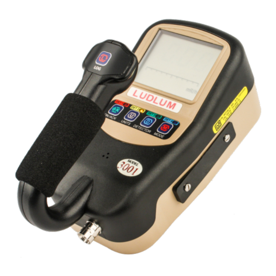
- Page 1 Model 3001 Multi-Detector Survey Meter Ludlum Measurements December 2021 Serial Number: 25009185 and Succeeding Firmware: n42.4810 and Higher...
- Page 3 Model 3001 Multi-Detector Survey Meter Ludlum Measurements December 2021 Serial Number: 25009185 and Succeeding Firmware: n42.4810 and Higher...
- Page 5 STATEMENT OF WARRANTY Ludlum Measurements, Inc. warrants the products covered in this manual to be free of de- fects due to workmanship, material, and design for a period of twelve months from the date of delivery. The calibration of a product is warranted to be within its specified accuracy lim- its at the time of shipment.
-
Page 9: Table Of Contents
Setup Mode Operation ....... . . 35 Model 3001 List of Parameters (in order) ..... . . 37 Setup Page 1 . - Page 10 AuxCom Setting - Encryption ......78 A.4.6 AuxCom Setting - Auto Mode Interval ....78 Ludlum Measurements, Inc.
-
Page 11: List Of Figures
IST OF IGURES Startup Display (All Segments Shown) ......12 Firmware Version Display ........12 Battery Voltage Display . -
Page 13: List Of Tables
IST OF ABLES COUNT Mode Units and Result ......23 Dead Time and Calibration Constant ......39 Primary Units and Multipliers . -
Page 15: Introduction
Three modes of operation are available for the Model 3001 – RATE, MAX, and COUNT. RATE mode operation will display the current count, exposure, or activity rate. - Page 16 It is located near the left handle base. If a headphone jack is not in use, the Model 3001 may optionally be provided with an RS- 232 serial output for connection to PC or other electronic device. For more advanced use:...
-
Page 17: Getting Started
Check individual item serial numbers and ensure calibration certificates match between instruments and de- tectors (if applicable). The Model 3001 serial number is located on a label on the front side of the unit. -
Page 18: Instrument Operational Test
Instead, use the following table to determine which main processor board is installed in the instrument: • 1 tick - 5498-440 • 2 ticks - 5519-042 • 3 ticks - 5519-773 Ludlum Measurements, Inc. -
Page 19: Battery Voltage Display
2.3. INSTRUMENT OPERATIONAL TEST The instrument then displays the battery voltage. Please see Figure below. Figure 2.3: Battery Voltage Display The instrument then displays the number of stored records if datalogging is enabled. Please refer to the figure below. Figure 2.4: Startup Display Showing 189 Stored Data Records The instrument will then move to normal operation, displaying the current rate for the Pri- mary units (factory default: mR/h). -
Page 20: Sigma Audio
fixed tone audio and a steady ALARM icon when a predetermined fixed alarm level is exceeded. 2.5 Detector Failure Diagnostics Note that the Model 3001 has its own diagnostic tests to ensure that the detector is function- ing correctly. 2.5.1 Detector Loss of Count If the detector stops detecting radiation for a settable number of seconds, the Model 3001 will flash the minimum display value to indicate which units have been affected by the loss... -
Page 21: Detector Over Range
Figure 2.6: Detector Over Range (Display Will Flash) 2.5.3 Detector Overload As another diagnostic test, the Model 3001 monitors the HV supply’s detector current. A cur- rent overload threshold can be set via Setup Mode or Lumic Software. (A setting of 0 disables this alarm.) In general, this alarm setting can be used to detect when there is some detec-... -
Page 22: Instrument Use And Controls
With four front-panel buttons and one handle button (as seen in front-panel drawing in front of manual), the Ludlum Model 3001 offers many features in a small package. Each button may be pressed and held for a predetermined length of time, signified by instrument beeps, to access unique instrument features. -
Page 23: Units Button
2.6. INSTRUMENT USE AND CONTROLS • During normal operation, it will acknowledge/silence alarms in any mode of opera- tion. • During normal operation, it will increment the audio through available volume levels which include mute and high if single audio is enabled or mute, low, and high if dual audio is enabled. -
Page 24: Detector Button
• Currently has no effect. Extra-Long Press (press and release after two beeps): • Device Menu: When viewing the detector current overload setpoint, this will switch the display between the live current reading and the set point value. Ludlum Measurements, Inc. -
Page 25: Mode Button
2.6. INSTRUMENT USE AND CONTROLS 2.6.4 MODE Button: The Mode button’s primary function is to switch between available enabled modes. Short Press (press and release before one beep): • During instrument initialization and within 4 seconds after the power-up screen, three short presses of the MODE button will place the instrument into setup mode. -
Page 26: Rate Mode Operation
RATE mode. If sigma audio and device rate reset are both enabled, the device rate reset will automatically be disabled. If other detectors are available, a short press of the DETECTOR will switch between available detectors as evidenced by the DET LEDs. Ludlum Measurements, Inc. -
Page 27: Max Mode Operation
2.8. MAX MODE OPERATION When switching detectors, it is recommended that the current detector be dis- connected from the instrument to prevent an unintended overvoltage from damaging the current detector. If other operational modes are available, a short press of the MODE button will move to the next available operational mode. -
Page 28: Count Mode Operation
Sigma audio is completely disabled in Count Mode. Audio ‘clicks’ are disabled in COUNT mode by default but may be enabled thru software (see Lumic 2.0 software parameter Dev- Ludlum Measurements, Inc. -
Page 29: Count Mode Units And Result
2.9. COUNT MODE OPERATION Cnt-Audio Mode). Adjusting Dev Cnt Audio Mode will enable or disable the click audio dur- ing a COUNT. • Off - always off • On - always on • W/Count - audio is only enabled during an active count If a result in terms of activity is desired, the scaler count can also be in units of "d"... - Page 30 When the Count Timer has Finished: • The display will show either the accumulated total for c, d, R, and Sv, or the timed ratemeter average for cps, cpm, dpm, or the average exposure or average dose in R/h and Sv/h. Ludlum Measurements, Inc.
- Page 31 2.9. COUNT MODE OPERATION • If datalogging is enabled and logging the count results was previously requested, the results will be logged to the log buffer. • A short press of the UNITS button will switch between the Primary and Secondary Count Units.
-
Page 33: Specifications
PECIFICATIONS Detectors: may be Geiger-Mueller (GM), scintillator, or proportional HV Range: 400-1500 Vdc Threshold Range: -4 to -100 mVdc, typically set to -35 mV for GM detectors Linearity: readings within 10% of true value Resolving Time: approximately 5 sec as defined by IEC 60325 Response Time: user-selectable from 1 to 60 seconds, auto-response rate of fast or slow Alarms: two adjustable count rate, exposure/dose, and count alarm setpoints adjustable over the display range... - Page 34 °C (-40 to 150 °F) Environmental Rating: NEMA (National Electrical Manufacturers Association) rating of 5 or IP (Ingress Protection) rating of 53 Size: 16.5 x 11.4 x 21.6 cm (6.5 x 4.5 x 8.5 in.) (H x W x L) Ludlum Measurements, Inc.
- Page 35 Weight: 0.7 kg (1.6 lb) (excluding detectors and clips) December 2021...
-
Page 37: Setup Mode
4.1 Setup Overview Your instrument has been shipped from Ludlum Measurements only after passing electronic checkout, a 24-hour burn-in process, and a careful calibration process. Calibration papers are supplied with each instrument shipped from Ludlum Measurements. -
Page 38: Setup Parameters
(dis- (dis- Alarm 1 (dis- abled) abled) abled) abled) abled) 000 R 000 R 000 Sv 000 R Unit 1 - Count Units counts P2-7 (dis- (dis- (dis- (dis- Alarm 2 (dis- abled) abled) abled) abled) abled) Ludlum Measurements, Inc. -
Page 39: Entering Setup Mode
Real Time Clock Second 4.3 Entering Setup Mode To enter Setup Mode, power down the Model 3001 then turn the unit back ON. When the instrument has begun normal operation, three short presses of the MODE button will place the instrument into Setup mode. - Page 40 If the menu is not exited properly, any changes made will not be saved. SETUP PROTECT: By default, the Model 3001 is shipped with DIP Switch 2 in the OFF (back) position and all available Model 3001 parameters may be modified in Setup mode. To pro-...
-
Page 41: Setup Mode Operation
Lumic 2.0 Calibration Software. 4.4 Setup Mode Operation Once the Model 3001 is in Setup mode, the detector selection will be displayed on the LCD and the detector number will be blinking indicating it as the selected item. Select the appro- priate detector using the DETECTOR button. -
Page 42: Setup Page Selection Display (Showing Page 4-Cal)
• Press the ON/ACK button to advance to the tens digit. • Press the MODE button to increment the value to 5. • Press the ON/ACK button to advance to the hundreds digit. • Press the MODE button to increment the value to 1. Ludlum Measurements, Inc. -
Page 43: Model 3001 List Of Parameters (In Order)
4.5. MODEL 3001 LIST OF PARAMETERS (IN ORDER) • Press the ON/ACK button to advance to the decimal point. • Press the MODE button to until no decimal is displayed. • Press the ON/ACK button to advance to the multiplier. - Page 44 • Dual Level Audio Page 5 • Datalogging Mode • Real Time Clock Month • Real Time Clock Day • Real Time Clock Year • Real Time Clock Hour • Real Time Clock Minute • Real Time Clock Second Ludlum Measurements, Inc.
-
Page 45: Setup
4.6. SETUP PAGE 1 Parameters on Page 5 are not user editable using the instrument Setup Mode. To edit these parameters, please use the Ludlum Lumic Calibration or Lumic Datalogging Software. 4.6 Setup Page 1 Calibration Constant Mantissa - A short press of ON/ACK to select the value to adjust, and MODE to adjust the value. - Page 46 Model 3001 display. But if the user desires to have the Model 3001 show results in terms of dpm/100 cm2, the user could manipulate the efficiency to produce this result by multiplying the efficiency times the ratio of the detector area to 100 cm2.
- Page 47 4.6. SETUP PAGE 1 • Tens Place (0-9) • Hundreds Place (0-9) • k Multiplier (on/off) Use the ON/ACK button to select the appropriate parameter, and use the MODE button to scroll through the parameter options. The k multiplier also activates left-most decimal point. If k multiplier is used, Hundreds Place becomes the Thousands Place, Tens Place becomes the Hun- dreds Place, and Ones Place becomes the Tens Place.
-
Page 48: Setup
MODE to adjust the value. Units will be the same as selected earlier with Primary Units. The ALARM LCD Segment will flash to indicate Alarm 1. Set this Alarm to 000 to disable. Available values are: • Ones Place (0-9) Ludlum Measurements, Inc. -
Page 49: Primary Unit Multipliers
4.7. SETUP PAGE 2 • Tens Place (0-9) • Hundreds Place (0-9) • Number of Decimal Places (0, 1, or 2) • Range (k on/off for cpm, cps, dpm, Bq; , m or none for R/h and Sv/h) If the Primary Units has changed to a value other than that used to previously set this Alarm Point, the Alarm Point will be reset to 000. -
Page 50: Setup
Secondary RATE/MAX Units and Minimum Display - A short press of the ON/ACK to select the value to adjust, and MODE to adjust the value. Available values are: • Number of Decimal Places (0, 1, or 2) • Minimum Units - See List Below Ludlum Measurements, Inc. -
Page 51: Secondary Units And Multipliers
4.8. SETUP PAGE 3 kcpm kcps kdpm mR/h Sv/h mSv/h Sv/h Table 4.5: Secondary Units and Multipliers Secondary Units RATE/MAX Maximum Display - A short press of ON/ACK to select the value to adjust, and MODE to adjust the value. Units will be the same as selected earlier with Secondary Units. -
Page 52: Secondary Unit Multipliers
• Range (k on/off for cpm, cps, dpm, Bq; , m or none for R/h and Sv/h) If the Secondary Count Units has changed to a value other than that used to previously set this Alarm Point, the Alarm Point will be reset to 000. Ludlum Measurements, Inc. -
Page 53: Setup
Setting the Response Time to a fixed value is useful primarily when per- forming surveys to a fixed MDA (Minimum Detectable Activity) level. Setting the Response Time to 0 will enable the Auto-Response mode for the Model 3001 (see the next parameter). Available values for the Response Time (in seconds) are: •... - Page 54 CHAPTER 4. SETUP MODE The Model 3001 also utilizes a Step function in Auto Response mode, which enables faster response to a significant increase or decrease in Count Rate. When the instrument detects a sudden change in count rate from the detector, the response time is reduced to 1 second to quickly show the new value.
-
Page 55: Setup
4.10. SETUP PAGE 5 • HI - Backlight comes on at a lower ambient light level. There are two different options for Backlight Threshold High, which can be set through the software. Locate the parameters in the Dev tab. Enter the desired number into the "Value"... -
Page 57: Datalogging
The datalogging feature of the Model 3001 allows the user to log radiation readings with the use of a handle-mounted LOG button. Data can be logged in any of the Model 3001’s oper- ational modes (RATE, MAX, and COUNT). Up to 1000 data points can be taken and stored internally. -
Page 58: Datalogging Operation - Mode 2
Mode 1. • The LCD display will show a possible Location ID Table index for the user. The index will be auto-incremented from the previously used index. Figure 5.2: Displaying Datalog Location ID Table Index of 36 Ludlum Measurements, Inc. -
Page 59: Datalogging Operation - Mode 3
5.3. DATALOGGING OPERATION – MODE 3 • The number will be blinking, indicating a changeable value. The user may then enter the preferred Location ID Table index by a short press of the MODE (to increment the value) as in Setup mode. •... -
Page 60: Data Log Operation
• Mode (1 Byte) • Detector Number (1 Byte) • Status (1 Byte) • Reserved (2 Bytes) • Elapsed Count Time in seconds (4 Bytes) • Scaler Count Time in seconds (4 Bytes) • Location ID (32 Bytes) Ludlum Measurements, Inc. -
Page 61: Software
OFTWARE 6.1 Connecting to Software The Model 3001 software is sent with a standard two-meter cable. (A five-meter cable can be provided if requested. However, any cable longer than two meters may have issues with some USB hubs and computers, typically laptops.) To connect an instrument to the computer, please connect one end of the USB cable to the instrument first, and then the other end to the computer. -
Page 63: Advanced Features
DVANCED EATURES 7.1 Dead Time Correction All pulse counting detectors have a “dead time” in which the detector is unable to register another event. In relatively low fields this is not an issue. However, as the field strength approaches the high end of the detector’s range, dead time causes the pulse rate to become non-linear with respect to the real radiation field. -
Page 64: R To Sv Conversion
Firmware Version: This is a read-only presentation of the firmware version. With a firmware version of F.x.y.zzzz, the F.x.y will show up on the device screen during the power-on sequence and signifies the released version. Ludlum Measurements, Inc. -
Page 65: Battery Life
7.7. BATTERY LIFE Device – Model Name: This should match the model name on the front face of the instrument. Device – Serial Number: This should match the serial number of the instrument. Detector – Model: This can store the model of the detectors the instrument was cali- brated for. -
Page 66: Cps Offset
fixed value, which must be configured while the instrument is connected to the Lumic Calibration 2.0 software and which is stored in the instrument and reused each time the instrument is powered on. By default, CPS Offset is 0 and no count subtraction is performed. Ludlum Measurements, Inc. -
Page 67: Safety Considerations
Not certified for use in an explosive atmosphere 8.2 Warning Markings and Symbols The Model 3001 Survey meter is marked with the following symbols: CAUTION (per ISO 3864, No. B.3.1): designates hazardous live voltage and risk of electric shock. During normal use, internal components are hazardous live. -
Page 68: Cleaning And Maintenance Precautions
Ludlum Mea- surements, Inc. 8.3 Cleaning and Maintenance Precautions The Model 3001 may be cleaned externally with a damp cloth, using only water as the wetting agent. Observe the following precautions when cleaning or performing maintenance on the instru- ment: •... -
Page 69: Revision History
EVISION ISTORY This section of the manual will be updated with each revision of the Model 3001 in order to document changes over time. Ludlum Measurements’ policy is to provide for free, the latest firmware release for an instrument for the life of that instrument. - Page 70 Bypass All as the fourth option for protect mode on page 32 and Display Backlight Continuous On on page 33. In Chapter 5: Datalogging on page 51, replaced Specifications with Section 5.4 Data Log Operation and Section 5.5 Format. In Ludlum Measurements, Inc.
- Page 71 Chapter 7: Advanced Features, added Section 7.5 Instrument Calibration, 7.7 Battery Life, 7.9 Button Mapping, and 7.10 CPS Offset. In Chapter 11: Options, changed Lumic Calibration Kit part number from 4498-1018 to 4519-563 and added RS-232 Serial port and TTL Serial Port.
-
Page 73: Recycling
To this end, Ludlum Measurements, Inc. strives to supply the consumer of its goods with information regarding reuse and recycling of the many different types of materials used in its products. -
Page 75: Options
It allows administrators to adjust device datalogging parameters. Headphone Option (part # 4498-555): This provides the Model 3000 series of instruments with a jack and circuitry required for a standard headphone plug. Ludlum Measurements also offers mono/stereo headphones with volume control. - Page 76 CHAPTER 11. OPTIONS TTL Serial Port: (part # 4519-155): This option adds a TTL 3.3 V serial port connector. Avail- able modes are instrument independent. Contact LMI for more information on configura- tion options. Ludlum Measurements, Inc.
-
Page 77: Standard Parts List
Model 3001 Digital Survey Meter 48-4036 Model 3000 Main Board 5519-042 Model 3001 Bezel Assembly 4498-476 Model 3001 Main Keypad Membrane Switch 7498-425 Model 3000 Handle Assembly with Datalogging 4498-428 Model 3000 Battery Holder Modified 7498-458 Model 3000 Unimorph with Harness 8498-542-01 LCD 82 mm x 61.64 mm... -
Page 79: A Auxiliary Communications
UXILIARY OMMUNICATIONS A.1 AuxCom Overview AuxCom, short for Auxiliary Communications, is a feature included on certain Ludlum in- struments. An AuxCom port allows the instrument to expand its capabilities with a variety of external devices through a standard serial interface. A.2 Requirements In order to take advantage of the AuxCom functionality, you will need the following: •... -
Page 80: Auxcom Usage - Pairing
4. Use 2-second Enable hot key to turn on WiFi. 5. Select “Scan” in App/Software. 6. When instrument is found by mobile device, select device in list and then “Pair.” 7. Enter PIN in App/Software from Step 2. Ludlum Measurements, Inc. - Page 81 A.3. USAGE Figure A.1: Example – Device Selection In Figure A.2: Example – Pairing Lumic Linker App (iOS) Figure A.3: Example – Model 3000 series Figure A.4: Example – Entering PIN In Lu- Found in Lumic Linker App (iOS) mic Linker App (iOS) December 2021...
-
Page 82: Settings
Raw Count: Mode that automatically transmits raw, uncorrected counts. The count interval is based on the AuxCom Auto Mode Interval variable. The output value is the cumulative counts that occurred in the previous interval on all enabled channels. Ludlum Measurements, Inc. -
Page 83: Auxcom Setting - Off Time
A.4. SETTINGS CPM: Mode that automatically transmits the CPM (counts per minute) for the external de- tector no matter what detector or mode is currently being displayed. The count interval is based on the AuxCom Auto Mode Interval variable. Display: Mode that automatically transmits the numeric value as well as units prefix, units, and units suffix for the currently displayed screen. -
Page 84: Auxcom Setting - Encryption
The table below shows valid settings. This setting only applies to Raw Counts mode as of this writing. Setting Description As fast as possible (1/4 second on Model 3000 series) 1-255 n-Seconds Table A.6: AuxCom Auto Mode Interval Ludlum Measurements, Inc.
Need help?
Do you have a question about the 3001 and is the answer not in the manual?
Questions and answers