
Related Manuals for Ludlum Measurements 3003i


Summary of Contents for Ludlum Measurements 3003i
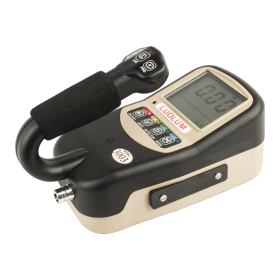
- Page 1 Model 3003 and 3003i Multi-Detector Survey Meter/SCA Ludlum Measurements January 2023 Serial Number: 25022487 and Succeeding Firmware: F.4.1.1208 and Higher...
- Page 3 Model 3003 and 3003i Multi-Detector Survey Meter/SCA Ludlum Measurements January 2023 Serial Number: 25022487 and Succeeding Firmware: F.4.1.1208 and Higher...
- Page 5 STATEMENT OF WARRANTY Ludlum Measurements, Inc. warrants the products covered in this manual to be free of de- fects due to workmanship, material, and design for a period of twelve months from the date of delivery. The calibration of a product is warranted to be within its specified accuracy lim- its at the time of shipment.
-
Page 7: Table Of Contents
ONTENTS Contents List of Figures List of Tables 1 Introduction 2 Getting Started Unpacking and Repacking ....... 13 Battery Installation . - Page 8 A.3 Usage ......... . . 95 Ludlum Measurements, Inc.
- Page 9 CONTENTS A.3.1 AuxComm Usage - Hot Key ......95 A.3.2 AuxComm Usage - Pairing ......96 A.4 Settings .
-
Page 11: List Of Figures
IST OF IGURES Startup Display (All Segments Shown) ......14 Hardware Revision Levels ........14 Firmware Version Display . -
Page 13: List Of Tables
IST OF ABLES COUNT Mode Units and Result ......29 Features That Affect Units in All Modes ......82 12.1 Standard Parts List . -
Page 15: Introduction
NTRODUCTION The Model 3003 and Model 3003i are ergonomic, lightweight instrument which can be used for radiation survey purposes. The Model 3003 features the ability to measure radiation in count rate, exposure rate/dose, activity rate, integrated exposure/dose, time-averaged rates, and scaler counts. It supports up to four external radiation detectors to detect alpha, beta, gamma, or neutron radiation. - Page 16 "find" something. They can simply listen for multiple beeps. Setup of the instrument is accomplished through the front-panel buttons, or through Lumic 2.0 software available from Ludlum Measurements. Front-panel setup can be disabled via the internal switch on the Model 3003 in order to pro- tect settings from inadvertent changes.
-
Page 17: Getting Started
ETTING TARTED 2.1 Unpacking and Repacking Remove the calibration certificate and place it in a secure location. Remove the instrument and ensure that all of the items listed on the packing list are in the carton. Check individual item serial numbers and ensure calibration certificates match between instruments and de- tectors (if applicable). -
Page 18: Turning The Instrument On
Instead, use the following table to determine which main processor board is installed in the instrument: • 1 tick - 5519-001 • 2 ticks - 5519-305 • 3 ticks - 5519-812 Ludlum Measurements, Inc. -
Page 19: Firmware Version Display
2.3. TURNING THE INSTRUMENT ON Use the following table to determine which high-voltage board is installed in the instrument (if any): • 1 tick - 5519-187 • 2 ticks - 5519-817 A revision level of 0 indicates that the board is not installed or detected. Next, the instrument displays the firmware version. -
Page 20: Instrument Diagnostics
This is a com- mon occurrence after installing new batteries into the instrument after an extended period without batteries (typically greater than 15 minutes). Figure 2.6: Instrument Date Reset (Audio Alarm) Ludlum Measurements, Inc. -
Page 21: Definitions
2.4. INSTRUMENT DIAGNOSTICS To acknowledge this condition, a short press of the ACK/RST button will silence the alarm, clear the screen, and resume normal instrument operation. A ’FAULT’ message will remain on the screen as a reminder until the instrument power is cycled. Time and date are necessary when the instrument is configured for datalogging as each log record is time/date stamped. -
Page 22: Instrument Operational Test
If desired, multiple readings may be taken at different distances and/or with different sources so that other scales are checked. Example of a Check Source reading: Check Source # Rate Units Once this procedure has been completed, the instrument is ready for use. Ludlum Measurements, Inc. -
Page 23: Sigma Audio
2.6. SIGMA AUDIO 2.6 Sigma Audio The Ludlum Model 3003 has the standard "click" audio that is widely used by radiation in- struments; however, it also has a Sigma Audio mode that can be enabled to change the audio sound. This mode is useful for scintillation detectors because their high count rate makes the "click"... -
Page 24: Detector Over Max
Setup Mode. (A setting of 0 disables this alarm.) In general, this alarm setting can be used to detect when there is some detector failure, a cable failure, or a possible high level of radiation. When this alarm is triggered, the LCD will display Ludlum Measurements, Inc. -
Page 25: Instrument Use And Controls
2.8. INSTRUMENT USE AND CONTROLS the OVERLOAD and ALARM icons, three dashes will be displayed in place of the numerical values, and an alarm tone will sound. Once the detector current goes below the threshold, the Model 3003 will return to normal operation. Figure 2.12: Detector Overload Alarm (Display Will Flash) 2.8 Instrument Use And Controls With four front-panel buttons and three handle buttons (as seen in front-panel drawing in... -
Page 26: Units Button
Long Press (press and release after two beeps): • Currently has no effect. Extra-Long Press (press and release after three beeps): • Enables/disables the Auxiliary Communications as indicated by a wifi symbol on the top of the LCD screen. Ludlum Measurements, Inc. -
Page 27: Detector Button
2.8. INSTRUMENT USE AND CONTROLS Figure 2.13: WiFi Symbol 2.8.3 DETECTOR Button: The Detector button’s primary function is to switch between available enabled detectors. Short Press (press and release after one beep): • Used to select the active detector, as evidenced by the corresponding DET1, DET2, DET3, or DET4 LED. -
Page 28: Ack/Rst Button
Short Press (press and release after one beep): • In RATE mode, it will log the current rate reading if datalogging is enabled. • In MAX mode, it will log the current MAX value if datalogging is enabled. Ludlum Measurements, Inc. -
Page 29: Prg Button
2.8. INSTRUMENT USE AND CONTROLS • In COUNT mode, it will: – If COUNT mode is ready: Initiate a count. Upon completion, the result will be logged if datalogging is enabled. – If COUNT mode is in progress: Button has no effect. –... -
Page 30: Rate Mode Operation
The word MAX will be displayed when in MAX mode. A short press of the UNITS button will switch the displayed value between the Primary and Secondary Units. If the detector is configured for alpha/beta, the UNITS button will switch Ludlum Measurements, Inc. -
Page 31: Count Mode Operation
2.11. COUNT MODE OPERATION between alpha and beta. A combination of alpha and beta (ex. alpha + beta) can be viewed if Unit 3 is enabled for the detector. A short press of the ON/AUD button will cycle through the “click” audio volume levels. When Sigma Audio is enabled, a short press of the ON/AUD will toggle the Sigma Audio volume levels. - Page 32 Similarly, if count units of Bq or dpm are chosen, the resulting answer is an averaged disintegration rate. Ludlum Measurements, Inc.
- Page 33 2.11. COUNT MODE OPERATION If the user desires the instrument to show results in terms of disintegra- tions/area (eg. dpm/100 cm ), then the instrument should be configured for dpm and the appropriate factor should be placed in the Efficiency parameter. Bq/cm will use the stored detector active area and perform the calculations internally so no manipulation of the efficiency is needed.
- Page 34 To clear the alarm condition and reset the Count Timer, an extra-long press of the ACK/RST button is required. • If other operational modes are available, a short press of the MODE button will move to the next available operational mode. Ludlum Measurements, Inc.
-
Page 35: Dose Mode Operation
2.12. DOSE MODE OPERATION Figure 2.16: COUNT Mode Displaying COUNT Timer of 5 Minutes, 30 Seconds Figure 2.17: COUNT Mode Displaying COUNT Timer of 100k Seconds When using COUNT mode on the Model 3003 i internal detector, it is possible for an internal detector integrated dose alarm to occur. -
Page 36: Dose Mode Operation Display
A short press of the LOG button, if datalogging is enabled, will log the currently displayed DOSE value. The maximum displayable value, regardless of units, is 999 M. Figure 2.18: DOSE Mode Operation Display Ludlum Measurements, Inc. -
Page 37: Specifications
PECIFICATIONS External Detector: may be Geiger-Mueller (GM), scintillator, proportional, or neutron; supports optional internal GM or scintillation detector Internal Detector (If installed): one energy-compensated GM tube with energy response within 25% of true value from 60 keV to 3 MeV (see note) Linearity: readings within 10% of true value LCD Display: three-digit LCD with bar graph, 13 units, five multipliers, two mode icons, three alarm levels, and four fault messages, as well as USB, wireless, audio, and low-battery... - Page 38 Weight: 0.9 kg (2.0 lb) (excluding detectors and clips) NOTE: Tested in a 100 mR/hr field. Testing in a 100 R/hr field yielded higher than expected response for energies greater than 1 MeV, but still within 40% of true value. Ludlum Measurements, Inc.
-
Page 39: Setup Mode
4.1 Setup Overview Your instrument has been shipped from Ludlum Measurements only after passing electronic checkout, a 24-hour burn-in process, and a careful calibration process. Calibration papers are supplied with each instrument shipped from Ludlum Measurements. -
Page 40: Setup Parameters
Background Alarms Audio Mode High Voltage Setpoint 1200 Calibration Constant Mantissa Calibration Constant Exponent Dead Time 36 e-6 10 e-6 5 e-6 5 e-6 80 e-6 Correction 1 Dead Time Correction 2 Mantissa Dead Time Correction 2 Exponent Ludlum Measurements, Inc. - Page 41 4.2. SETUP PARAMETERS Model Model Alpha Model Internal Setting Setup Parameter 133-6 44-2 or Beta 42-31H Detector Detector Current Overload Threshold Detector Adjustable 0 (continuous) Scaler Count Detector Active Area Channel 1 – 0.035 0.035 0.0035 0.004 0.035 Threshold (V) Channel 1 - Window 0 (max value) 0.03...
- Page 42 Unit 2 - DOSE Alarm 2.00 kc Unit 2 - DOSE Alarm 5.00 kc Unit 2 - DOSE Alarm 8.00 kc Unit 2 - Channel Unit 3 - RATE / MAX Units and Minimum 0 (No unit) 0 (No unit) Display Ludlum Measurements, Inc.
-
Page 43: Entering Setup Mode
4.3. ENTERING SETUP MODE Model Model Alpha Model Internal Setting Setup Parameter 133-6 44-2 or Beta 42-31H Detector Unit 3 - RATE / MAX 10.0 0 (No unit) 0 (No unit) Maximum Display Mcpm Unit 3 - RATE / MAX 2.00 0 (No unit) 0 (No unit) - Page 44 This plastic cover is left on the dipswitch after assembly and is not removed until the dipswitch is needed. If the plastic cover still remains on the dipswitch, please remove the cover before changing the switch settings. Ludlum Measurements, Inc.
-
Page 45: Backlight/Setup Protect Dipswitch
4.3. ENTERING SETUP MODE Figure 4.1: Backlight/Setup Protect Dipswitch There are four different options for protect mode, which can be set through the Lumic 2.0 Calibration Software. Locate the Parameter “Setup Prtct” in the Dev tab and select the de- sired option. -
Page 46: Setup Mode Operation
DETECTOR button until the appropriate detector LED is illuminated will allow the user to see and change the value for the selected detector. For example: Set Detector 1, Rate Mode, Unit 1, Alarm 1 Value to 150 mR/h. Ludlum Measurements, Inc. -
Page 47: Model 3003 List Of Parameters (In Order)
4.5. MODEL 3003 LIST OF PARAMETERS (IN ORDER) Enter the Setup Menu. Use the PRG or ACK/RST buttons to advance to U-1. Press the LOG button to enter the menu. (The first value is shown and the appropriate LED should illumi- nate). - Page 48 • Detector Adjustable Scaler Count Time • Detector Active Area Page 5 - CH_1 • Channel 1 - Threshold • Channel 1 - Window • Channel 1 - Efficiency • Channel 1 - Loss of Count Alarm Time Ludlum Measurements, Inc.
- Page 49 4.5. MODEL 3003 LIST OF PARAMETERS (IN ORDER) • Channel 1 - Icon Page 6 - CH_2 • Channel 2 - Threshold • Channel 2 - Window • Channel 2 - Efficiency • Channel 2 - Loss of Count Alarm Time •...
- Page 50 • Unit 3 - DOSE Units and Minimum Display • Unit 3 - DOSE Alarm 1 • Unit 3 - DOSE Alarm 2 • Unit 3 - DOSE Alarm 3 • Unit 3 - Channel Page 10 - rst • Erase Storage (WARNING!!!) Ludlum Measurements, Inc.
-
Page 51: Device
4.6. PAGE 1 - DEVICE 4.6 Page 1 - Device To begin adjusting a device parameter, short press the PRG or ACK/RST to scroll through the available device parameters. Next, short press LOG to begin modifying the parameter chosen. Finally, extra-long pressing the LOG button will complete the modification. Default settings are in bold. - Page 52 Use the PRG and ACK/RST buttons to scroll through the parameter options. Real Time Clock Year - Upon entry into Real Time Clock Year, one of the following parame- ters will be selected (flashing). • Ones Place (0-9) Ludlum Measurements, Inc.
-
Page 53: Datalogging
4.7. PAGE 2 - DATALOGGING • Tens Place (0-9) • Hundreds Place (0-9) Thousands place is assumed to be two (for 2000). Use the LOG button to select the appro- priate parameter and use the PRG and ACK/RST buttons to scroll through the parameter options. -
Page 54: Configuration
Default settings are in bold. Detector Enable - Upon entry into Detector Enabled, the parameter will be selected (flash- ing) indicating the state of the parameter. • on (detector is enabled) • off (detector is disabled) Ludlum Measurements, Inc. -
Page 55: Detector Operation Modes
4.8. PAGE 3 - CONFIGURATION Use the PRG and ACK/RST buttons to scroll through the available parameter options. Operation Modes - Upon entry into Operation Modes, the parameter will be selected (flash- ing) indicating the state of the parameter. A picture of the LCD is below. Figure 4.3: Detector Operation Modes Each mode is represented on the LCD screen as follows: •... - Page 56 figurations utilize both channels so when enabled both alpha and beta click audio can be heard all the time. Background Alarms - Upon entry into Background Alarms, the parameter will be selected (flashing) indicating the state of the parameter. • on (background alarms are enabled) • off (background alarms are disabled) Ludlum Measurements, Inc.
-
Page 57: Calibration
4.9. PAGE 4 - CALIBRATION Use the PRG and ACK/RST buttons to scroll through the available parameter options. Audio Mode- Upon entry into Audio Mode, the parameter will be selected (flashing) indicat- ing the state of the parameter. • Sig (Sigma audio) •... - Page 58 Use the LOG button to select the appropriate parameter and use the PRG and ACK/RST but- tons to scroll through the parameter options. Dead Time Correction 2 Exponent - Upon entry into Dead Time Correction 2 Exponent, the exponent will be flashing. • Exponent (-6 to -15) Ludlum Measurements, Inc.
- Page 59 4.9. PAGE 4 - CALIBRATION Use the PRG and ACK/RST buttons to scroll through the parameter options. Detector Current Overload Threshold - Upon entry into Detector Current Overload Thresh- old, one of the following parameters will be selected (flashing). • Rightmost Digit (0-9) •...
-
Page 60: Channel 1
Channel 1 – Efficiency (%) - Upon entry into Channel 1 Efficiency, one of the following pa- rameters will be selected (flashing). • Rightmost Digit (0-9) • Middle Digit (0-9) • Leftmost Digit (0-9) • Multiplier (m/<>) with all digits flashing (adjustable from xxx m to xxx) Ludlum Measurements, Inc. - Page 61 4.10. PAGE 5 - CHANNEL 1 Use the LOG button to select the appropriate parameter, and use the PRG and ACK/RST buttons to scroll through the parameter options. Channel 1 - Loss of Count Alarm Time - Upon entry into Channel 1 Loss of Count Time, one of the following parameters will be selected (flashing).
-
Page 62: Channel 2
Channel 2 – Efficiency (%) - Upon entry into Channel 2 Efficiency, one of the following pa- rameters will be selected (flashing). • Rightmost Digit (0-9) • Middle Digit (0-9) • Leftmost digit (0-9) • Multiplier (m/<>) with all digits flashing (adjustable from xxx m to xxx) Ludlum Measurements, Inc. - Page 63 4.11. PAGE 6 - CHANNEL 2 Use the LOG button to select the appropriate parameter, and use the PRG and ACK/RST buttons to scroll through the parameter options. Channel 2 - Loss of Count Alarm Time - Upon entry into Channel 2 Loss of Count Time, one of the following parameters will be selected (flashing).
-
Page 64: Unit 1
Unit 1 - RATE/MAX Alarm 1 - Upon entry into Unit 1 RATE/MAX Alarm 1, one of the following parameters will be selected (flashing). • Rightmost Digit (0-9) • Middle Digit (0-9) • Leftmost Digit (0-9) Ludlum Measurements, Inc. - Page 65 4.12. PAGE 7 - UNIT 1 • Multiplier with all digits flashing (adjustable from x.xx to xxx M depending on unit selected) Use the LOG button to select the appropriate parameter, and use the PRG and ACK/RST buttons to scroll through the parameter options. Unit 1 - RATE/MAX Alarm 2 - Upon entry into Unit 1 RATE/MAX Alarm 2, one of the following parameters will be selected (flashing).
- Page 66 Unit 1 - COUNT Alarm 3 - Upon entry into Unit 1 Count Alarm 3, one of the following pa- rameters will be selected (flashing). • Rightmost Digit (0-9) • Middle Digit (0-9) • Leftmost Digit (0-9) • Multiplier with all digits flashing (adjustable from x.xx to xxx M depending on unit selected) Ludlum Measurements, Inc.
- Page 67 4.12. PAGE 7 - UNIT 1 Use the LOG button to select the appropriate parameter, and use the PRG and ACK/RST buttons to scroll through the parameter options. Unit 1 - DOSE Units and Minimum Display - Upon entry into Unit 1 RATE/MAX Units Max- imum Display, one of the following parameters will be selected (flashing).
-
Page 68: Unit 2
Select Unit first before setting other parameters. • Rightmost Digit (0-9) • Middle Digit (0-9) • Leftmost digit (0-9) • Multiplier with all digits flashing (adjustable from x.xx to x.xx k) • Unit (off, dpm, Bq, Bq/cm , cpm, cps, Rem/h, R/h, Sv/h) Ludlum Measurements, Inc. - Page 69 4.13. PAGE 8 - UNIT 2 Use the LOG button to select the appropriate parameter, and use the PRG and ACK/RST buttons to scroll through the parameter options. Unit 2 - RATE/MAX Maximum Display - Upon entry into Unit 2 RATE/MAX Units Maximum Display, one of the following parameters will be selected (flashing).
- Page 70 Unit 2 - COUNT Alarm 2 - Upon entry into Unit 2 Count Alarm 2, one of the following pa- rameters will be selected (flashing). • Rightmost Digit (0-9) • Middle Digit (0-9) • Leftmost Digit (0-9) Ludlum Measurements, Inc.
- Page 71 4.13. PAGE 8 - UNIT 2 • Multiplier with all digits flashing (adjustable from x.xx to xxx M depending on unit selected) Use the LOG button to select the appropriate parameter, and use the PRG and ACK/RST buttons to scroll through the parameter options. Unit 2 - COUNT Alarm 3 - Upon entry into Unit 2 Count Alarm 3, one of the following pa- rameters will be selected (flashing).
- Page 72 Valid parameter options are as follows: • 1 (Channel 1) • 2 (Channel 2) • 1i (Internal Detector Only) Use the PRG and ACK/RST buttons to scroll through the parameter options. Ludlum Measurements, Inc.
-
Page 73: Unit 3 (If Supported)
4.14. PAGE 9 - UNIT 3 (IF SUPPORTED) 4.14 Page 9 - Unit 3 (if supported) To begin adjusting a unit parameter, short press the PRG or ACK/RST to scroll through the available unit parameters. When the appropriate parameter is selected, short press DETEC- TOR to select the detector that needs the parameter adjusted. - Page 74 first before selecting multiplier. • Multiplier with all digits flashing (adjustable from x.xx to xxx M depending on unit selected) • Unit (off, d, dpm, Bq, Bq/cm , c, cps, cpm, Rem, Rem/h, R, R/h, Sv, Sv/h) Ludlum Measurements, Inc.
- Page 75 4.14. PAGE 9 - UNIT 3 (IF SUPPORTED) Use the LOG button to select the appropriate parameter and use the PRG and ACK/RST but- tons to scroll through the parameter options. Unit 3 - COUNT Alarm 1 - Upon entry into Unit 3 Count Alarm 1, one of the following pa- rameters will be selected (flashing).
- Page 76 Unit 3 - DOSE Alarm 2 - Upon entry into Unit 3 Dose Alarm 2, one of the following parame- ters will be selected (flashing). • Rightmost Digit (0-9) • Middle Digit (0-9) • Leftmost digit (0-9) • Multiplier with all digits flashing (adjustable from x.xx to xxx M depending on unit selected) Ludlum Measurements, Inc.
-
Page 77: Reset (Warning!!!)
4.15. PAGE 10 - RESET (WARNING!!!) Use the LOG button to select the appropriate parameter and use the PRG and ACK/RST but- tons to scroll through the parameter options. Unit 3 - DOSE Alarm 3 - Upon entry into Unit 3 Dose Alarm 3, one of the following parame- ters will be selected (flashing). -
Page 79: Datalogging
ATALOGGING The datalogging feature of the Model 3003, accessible through the use of the optional Lumic Datalogger software kit, allows the user to log radiation readings with the use of a handle- mounted LOG button. Data can be logged in any of the Model 3003’s operational modes (RATE, MAX, and COUNT). -
Page 80: Datalogging Operation - Mode 2
– For a continuous Scaler count (Scaler time is 0), the LOG button is enabled at all times. • The LCD display will show a possible Location ID Table index for the user. The index will be auto-incremented from the previously used index. Ludlum Measurements, Inc. -
Page 81: Datalogging Operation - Mode 3
5.3. DATALOGGING OPERATION – MODE 3 Figure 5.2: Displaying Datalog Location ID Table Index of 36 • The number will be blinking, indicating a changeable value. The user may then enter the preferred Location ID Table index by a short press of the PRG (to increment the value) or ACK/RST (to decrement the value) buttons as in Setup mode. -
Page 82: Format
• Mode (1 Byte) • Detector Number (1 Byte) • Status (1 Byte) • Reserved (2 Bytes) • Elapsed Count Time in seconds (4 Bytes) • Scaler Count Time in seconds (4 Bytes) • Location ID (32 Bytes) Ludlum Measurements, Inc. -
Page 83: Software
OFTWARE 6.1 Connecting to Lumic 2.0 Calibration/Configuration Software The Lumic 2.0 Calibration/Configuration software is sent with a standard two-meter cable. (A five-meter cable can be provided if requested. However, any cable longer than two meters may have issues with some USB hubs and computers, typically laptops.) To connect an instrument to the computer, please connect one end of the USB cable to the instrument first, and then the other end to the computer. -
Page 85: Advanced Features
DVANCED EATURES 7.1 Dead Time Correction All pulse counting detectors have a “dead time” in which the detector is unable to register another event. In relatively low fields this is not an issue. However, as the field strength approaches the high end of the detector’s range, dead time causes the pulse rate to become non-linear with respect to the real radiation field. -
Page 86: R To Sv Conversion
However, if calibration is required (due to board rework, etc.) the calibration settings are available in Lumic Calibra- tion software. 7.6 Other Device Data The following parameters on the instrument allow recording import device information within the device: Ludlum Measurements, Inc. -
Page 87: Battery Life
7.7. BATTERY LIFE Firmware Version: This is a read-only presentation of the firmware version. With a firmware version of F.x.y.zzzz, the F.x.y will show up on the device screen during the power-on sequence and signifies the released version. Device – Model Name: This should match the model name on the front face of the instrument. -
Page 89: Safety Considerations
AFETY ONSIDERATIONS 8.1 Environmental Conditions for Normal Use Indoor or outdoor use (While rain resistant, user is cautioned to avoid getting water through detector opening.) No maximum altitude Temperature range of -20 to 50 °C (-5 to 122 °F), may be certified for operation from -40 to 65 °C (-40 to 150 °F) Maximum relative humidity of less than 95% (non-condensing) Pollution Degree 3 (as defined by IEC 664): (Occurs when conductive pollution or dry... -
Page 90: Cleaning And Maintenance Precautions
Observe the following precautions when cleaning or performing maintenance on the instru- ment: • Turn the instrument OFF and remove the batteries. • Allow the instrument to sit for one minute before cleaning the exterior or accessing any internal components for maintenance. Ludlum Measurements, Inc. -
Page 91: Revision History
March 2021: In Section 3 Specifications under User Controls for "ON/AUD" added "plus 3 seconds;" under Detector in this section added what to do for Model 3003i only; under Mode changed 0 to 115.625 days to 0 to approximately 31.68 years; also added ACK/RST, LOG, and PRG. - Page 92 Added AuxCOM Power Mode and AuxCOM Auto Interval to Chapter 4 Setup Parameters Ta- ble, Page Descriptions, and Device Descriptions. Changed AuxCOM COM Mode description to show values are now reported as text instead of numeric in the Setup Menu. Ludlum Measurements, Inc.
-
Page 93: Recycling
To this end, Ludlum Measurements, Inc. strives to supply the consumer of its goods with information regarding reuse and recycling of the many different types of materials used in its products. -
Page 95: Options
It allows administrators to adjust device datalogging parameters. Headphone Option (part # 4498-555): This provides the Model 3000 series of instruments with a jack and circuitry required for a standard headphone plug. Ludlum Measurements also offers mono/stereo headphones with volume control. -
Page 97: Standard Parts List
Main Keypad Membrane Switch 7519-239 Handle Log Button Switch 7519-199 Battery Holder Modified 7498-458 Model 3000 GEN 2 USB Cover Assembly 4519-572 Model 3003i High Voltage Detector Board 5519-817 Lumic and Lumic 2.0 Calibration Software 1370-124 Table 12.1: Standard Parts List... -
Page 99: A Auxiliary Communications
UXILIARY OMMUNICATIONS A.1 AuxComm Overview AuxComm, short for Auxiliary Communications, is a feature included on certain Ludlum in- struments. An AuxComm port allows the instrument to expand its capabilities with a variety of external devices through a standard serial interface. A.2 Requirements In order to take advantage of the AuxComm functionality, you will need the following: •... -
Page 100: Auxcomm Usage - Pairing
4. Use 2-second Enable hot key to turn on WiFi. 5. Select “Scan” in App/Software. 6. When instrument is found by mobile device, select device in list and then “Pair.” 7. Enter PIN in App/Software from Step 2. Ludlum Measurements, Inc. - Page 101 A.3. USAGE Figure A.1: Example – Device Selection Figure A.2: Example – Pairing In Lumic Linker App (iOS) Figure A.3: Example – Model 3000 series Figure A.4: Example – Entering PIN In Found in Lumic Linker App (iOS) Lumic Linker App (iOS) January 2023...
-
Page 102: Settings
Raw Count: Mode that automatically transmits raw, uncorrected counts. The count interval is based on the AuxComm Auto Mode Interval variable (see A.4.6). The output value is the cumulative counts that occurred in the previous interval on all enabled channels. Ludlum Measurements, Inc. -
Page 103: Auxcomm Setting - Off Time
A.4. SETTINGS CPM: Mode that automatically transmits the CPM (counts per minute) for the external de- tector no matter what detector or mode is currently being displayed. The count interval is based on the AuxComm Auto Mode Interval variable (see A.4.6). Display: Mode that automatically transmits the numeric value as well as units prefix, units, and units suffix for the currently displayed screen. -
Page 104: Auxcomm Setting - Encryption
This setting controls the number of seconds for each transmitted value in automatic stream modes. The table below shows valid settings. Table A.6: AuxComm Auto Mode Interval Setting Description As fast as possible (1/4 second on Model 3000 series) 1-255 n-Seconds Ludlum Measurements, Inc.
Need help?
Do you have a question about the 3003i and is the answer not in the manual?
Questions and answers