Table of Contents
Advertisement
Quick Links
Advertisement
Table of Contents

Subscribe to Our Youtube Channel
Related Manuals for Texi Iris 10


Summary of Contents for Texi Iris 10
- Page 1 MANUAL...
-
Page 2: Table Of Contents
Texi Iris 10 Operation Manual TABLE OF CONTENTS SAFETY RULES…………………………………………………………….…………..3 Machine construction and main functions………………………………………….…5 10-needle embroidery machine………………………………………………………………….5 LCD panel………………………………………………………………………………………….5 USB port……………………………………………………………………………………………6 Needle bar positioning……………………………………………………………………………6 Safety device………………………………………………………………………………………6 Machine basic parts and their functions……………………………………..7 Front view…………………………………………………………………………………………..7 Right/rear view………………………………………………………………………………….….8 Panel LCD main buttons………………………………………………………………………..9 Accessories………………………………………………………………………………………...9... -
Page 3: Safety Rules
Texi Iris 10 Operation Manual SAFETY RULES This instruction manual contains important guidelines regarding correct, safe and economical method of use of the machine. Following recommendations contained in this manual will decrease work down-time, increase machine reliability and durability, and will make work safer. - Page 4 Texi Iris 10 Operation Manual Turn machine off before: replacing needle, threading, installing attachments, changing the bobbin or bobbin case. If you notice any abnormalities in the machine’s function, turn it off immediately and inform a mechanic or your superior.
-
Page 5: Machine Construction And Main Functions
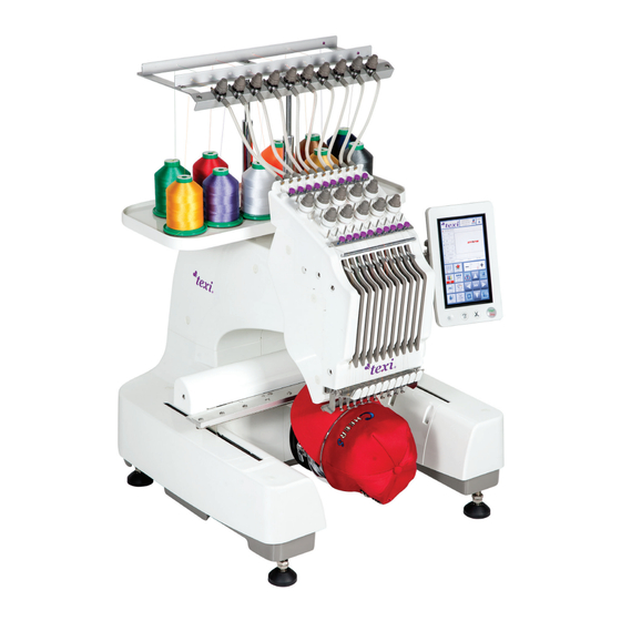
Texi Iris 10 Operation Manual Machine construction and main functions 10-needle embroidery machine Machine is equipped with 10 needles, each needle can embroider with a different thread colour. By setting the colour and auto- matic colour change for each needle bar, user may embroider patterns of various colours. Needle bars are named in the follow- ing order: 10#, 9#, 8#, 7#, 6#, 5#, 4#, 3#, 2#,1#. -
Page 6: Usb Port
Texi Iris 10 Operation Manual USB port Embroidery can be connected with computer by a network cable. User may transmit embroidery pattern via USB. Panel is equipped with USB port and network socket. To implement patterns to the machine, user can use USB flash drive with previously saved pattern and then deliver them to the embroidery machine. -
Page 7: Machine Basic Parts And Their Functions
Texi Iris 10 Operation Manual Machine parts and their func ons basic Front view Name Description Threading mechanism Guide the threads through marked holes and adjust tension Needle bar frame Needle bar frame moves horizontally and sets the needle to embroidery position Guide rail Install embroidery frame in guide rail. -
Page 8: Right/Rear View
Texi Iris 10 Operation Manual Right/rear view Name Description USB port Import or export of embroidery patterns via USB by inserting USB flash drive into USB port Network port Connects the computer with embroidery machine Power switch For switching the machine on/off Power socket Enables inserting of power plug into the power socket. -
Page 9: Panel Lcd Main Buttons
Texi Iris 10 Operation Manual Panel LCD main bu ons Name Description Loudspeaker It produces a sound when embroidery operation is over or thread is broken. Jog key Shaft turns to 100° position Thread-cutting key Manual thread-cutting button * Red light on: ready to work... -
Page 10: Machine Installation
Texi Iris 10 Operation Manual Machine installation Machine installation procedures are described below and if machine is not correctly installed, shaking or noise may occur and patterns can’t be correctly embroidered. Precautions for installation and transportation Maximum operating environment temperature is 5° C (4 0° F) to 4° C (104° F), and machine operating in a hot or cold environment may cause permanent damages. -
Page 11: Adjusting The Height Of The Machine
Texi Iris 10 Operation Manual To prevent malfunction or damage, the machine cannot be exposed to the following conditions: For safety purpose: Do not install the machine on an unstable or weak platform. Machine installation Keep the machine stable by regulating nuts. -
Page 12: Regulation Panel
Texi Iris 10 Operation Manual Regulation of the panel Loosen two regulation screws and move operation panel Adjust the position of the panel by using regulation screws forward. Tighten both screws. (1). Other positions of the panel are possible by loosening... - Page 13 Texi Iris 10 Operation Manual Tighten two parts of the thread base with 4 screws M4x8 (1). Select 10 bobbin columns (2) and install them on the On every bobbin column (out of 10) you can install one bobbin thread rack (1).
-
Page 14: Installation Of Embroidery Frame
Texi Iris 10 Operation Manual Install the thread rack guide tube (1) on the thread base (2), and lock it with the guide tube nut (3). 1.Thread rack module and guide tube 2. Thread rack 3. Nut Install the assembled thread rack (1) on the machine head on two positioning dowels, and tighten nut (2) with hex wrench, and nut (3) 1. -
Page 15: Basic Steps Before Starting Embroidering
Texi Iris 10 Operation Manual Connect embroidery frame (2) with the plate using 2 screws M4x8 (1). Basic steps before starting embroidering Bobbin installation Notes: In a new machine only a bobbin case without a bobbin is installed. To start work please insert a bobbin with bobbin thread for embroidery. -
Page 16: Inserting Bobbin Into Bobbin Case
Texi Iris 10 Operation Manual Grab the bobbin case bolt (1), and take out the bobbin Lubrication of bobbin case base case. After removing the bobbin case, lubricate the bobbin case base area (2) using SPIRIT 2 (1). Once lubricated insert the bobbin into the bobbin case and place it in the machine. -
Page 17: Bobbin Case Installation
Texi Iris 10 Operation Manual Bobbin case installation Insert the bobin case into the bobbin case base (2) in a Insert the bobbin case until it is completely placed. way that the outstanding part of the bobbin case (1) is parallel tot he hollow in the bobbin case base (2). -
Page 18: Main Functions On The Lcd Panel
Texi Iris 10 Operation Manual Main functions on the LCD panel After turning the machine on, user may proceed with the following operations by using the operation panel. TEXI.DST LED lamp switch ON/OFF LED lamp Pattern preview zone Displays selected pattern, previews embroidery frame movement posi-... -
Page 19: Pattern Input
Texi Iris 10 Operation Manual Pattern input Enter pattern selection interface by touching (1), as shown be- Insert USB flash drive with already saved pattern, to low: USB port on the side of operation panel Select USB flash drive catalogue by touching (1). Select pattern by touching (2), and copy it to the machine memory by touching (3). -
Page 20: Select Embroidery Pattern
Texi Iris 10 Operation Manual Select embroidery pattern For instance, we select the pattern shown below. To view the pattern touch (1). Select machine memory by touching (1), and then touch (2) to select pattern, confirm by OK button. Select embroidery frame (hoop) After selecting embroidery pattern, confirm the embroi- To choose the correct hoop for the pattern touch (1). -
Page 21: Put Material On Embroidery Frame (Hoop)
Texi Iris 10 Operation Manual Select embroidery frame (for example D) by touching its icon Choose embroidery frame (hoop) dimension by touching and click OK to confirm. one of below options, for example D (1). Four dimensions of embroidery frame (hoops) are available. -
Page 22: Install Embroidery Frame In The Machine
Texi Iris 10 Operation Manual Tighten screws slightly, pull cloth/material edges out. Put the internal frame into the external one. Make sure the cloth is free from wrinkles before you in- stall it in the machine. 1) After securing the cloth in the embroidery frame, knock the cloth slightly. - Page 23 Texi Iris 10 Operation Manual Loosen two screws on embroidery frame stand. Notes: 1. The left arm of embroidery frame stand can move left or right. 2. Loosen screw s(1) counter clockwise but do not remove the screw which will make further installation easier.
-
Page 24: Check Embroidery Area
Texi Iris 10 Operation Manual Check embroidery area Check embroidery area, make sure that embroidery will be made in a desired place, free from crumpets, and that the embroidery frame will not collide with presser foot. If the position of embroidery frame is incorrect, please move it to the correct position. - Page 25 Texi Iris 10 Operation Manual Next thread the machine as shown below. Pull out the thread from the bobbin and the lead thread Lead the threader (1) through the thread guide (2), clamp respectively through the thread guide hole (1) (2) (3) (4), thread with the clip on the threader and pull the thread out to ensure smooth threading.
- Page 26 Texi Iris 10 Operation Manual Raise the clip (1) to press the thread and complete thread- Lead the thread through take-up-lever (1) hole from ing according to the guide line on machine case (2) & (3). right to the left as shown below.
-
Page 27: Starting Embroidery
Texi Iris 10 Operation Manual Starting embroidery Note: Before starting embroidery always make sure that the chosen pattern corresponds with the selected size of the embroidery frame, as well as the embroidering frame has been installed correctly. To start the machine, press Start/Stop button in the right bottom corner of the machine. -
Page 28: Take Off Embroidery Frame And Material
Texi Iris 10 Operation Manual User may see the bottom thread from the right side of the cloth since the upper thread tension is too tight. Since the upper thread tension is too low, the upper thread Rotate the tension knob clockwise to decrease the thread tension. -
Page 29: Shutdown
Texi Iris 10 Operation Manual Shutdown Always turn off the machine when you stop working To switch off the machine set the main power switch at “o” 1. Pull out power cords from the power socket. 2. Pull out power cords from the machine, if necessary In case of power failure during embroidery machine operation, please shut down embroidery machine and pull out power cords. -
Page 30: Pattern Selection And Management Interface
Texi Iris 10 Operation Manual Display coordinate parameter Pa ern display area Display the range of current em- Display current posi on of the broidery frame needle and spindle Reduce embroidery speed Pa ern selec on and Increase embroidery speed... -
Page 31: Embroidering Colour Setting Interface
Texi Iris 10 Operation Manual Embroidering colour setting interface Icon Desrciption Set offset point Low-speed embroidery Switching needle bar Color change mode Down Pattern setting interface Icon Description X-direc on scaling Pa ern rota on angle Number of X-direc on array... -
Page 32: Profile Use Interface
Texi Iris 10 Operation Manual Profile user interface Icon Description User limit setting IP setting Letter library Software information Origin operation Unlock user limitation Display colour settings Power-on automatic reset- ting Language setting Machine testing Needle replacement In case of needle bending or needle point breakage,please replace with a new one using the attached screwdriver. -
Page 33: Easy Replacement Of Bobbin
Texi Iris 10 Operation Manual ·Keep the flat side at needle point facing the front of the machine, push the needle until you notice resistance and tighten the screw with the screwdriver. Easy replacement of bobbin Before bobbin replacement, complete upper threading, but if bobbin is correctly threading on the machine, it may be easier to replace the bobbin. - Page 34 Texi Iris 10 Operation Manual CE DECLARATION OF CONFORMITY Distributor: Strima Sp. z o.o. Swadzim, ul. Poznańska 54 62-080 Tarnowo Podgórne, Poland We declare, that the following product: Ebroidery machine TEXI IRIS 10 (EM1010) With this declaration relates, complies with following directives:...
Need help?
Do you have a question about the Iris 10 and is the answer not in the manual?
Questions and answers