Table of Contents
Advertisement
Quick Links
Antaira Technologies
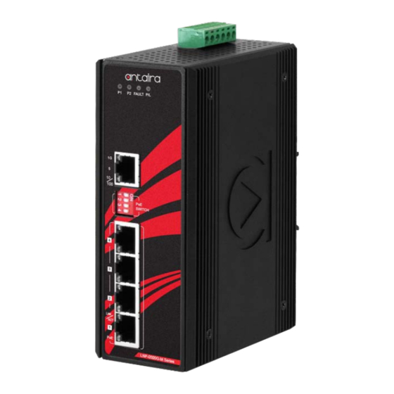
LNP-0500G-bt Series
5-Port Industrial Gigabit IEEE 802.3bt Unmanaged Ethernet
Switch, w/4*10/100/1000Tx (90W/Port) + 1*10/100/1000Tx
Quick Installation Guide
Version 1.0
(May 2020)
Tel: 1-844-268-2472
Fax: 1-714-671-9944
www.antaira.com
Package Check List
The package contains the following items:
1 – Quick installation guide
1 – LNP-0500G-bt(-T)
1 – Wall mounting bracket set with screws
1 – DC cable –18 AWG & DC jack 5.5 x 2.1mm
1 – RJ45 dust cover set
Front Panel Layout
Grounding Screw
LED for Power 1, Power 2, Fault
and PoE Load
LAN# 5 – LED for Link/Activity Status
1000Mbps
LAN# 5 – LED for Link/Activity Status
10/100Mbps
DIP Switch
LAN# 1~4 – LED for Link/Activity Status
10/100/1000Mbps
LAN# 1~4 – LED for PoE Status
Top Panel View
LNP-0500G-bt series top panel is equipped with one 6-pin
removal terminal block connector for dual DC power inputs
(48~55VDC).
6-Pin Removal Terminal Block (Power Input)
Product Overview
System Interface/Performance
All RJ45 ports support the auto MDI/MDI-X function
Embedded 4*10/100/1000Tx RJ45 ports (90W/Port) and
1*10/100/1000Tx RJ45 port
Store-and-forward switching architecture
8K MAC Address Table
Supports 10Kbytes jumbo frame
1Mbit memory buffer
19020000000132
Power Input & Connection
DC 48 to 55V redundant power, with a 6-pin removal
terminal block
Max. current: 3.9A
Max. PoE output: 180W
It is recommended to use a UL listed industrial power supply
Operating Temperature
Standard Operating Temperature model: -10°C to 65°C
Extended Operating Temperature model: -40°C to 75°C
Case/Installation
IP30 Protection
6-Pin Removal Terminal Block (Power Input)
DIN-Rail and Wall Mount Design
PoE DIP Switch
DIP Switch Number
PoE DIP Switch 1
PoE DIP Switch 2
LAN# 1~5 – 10/100/1000Tx RJ45
PoE DIP Switch 3
PoE DIP Switch 4
LED Indicators
LED
Power 1
Power 2
Fault
Grounding Screw
PoE Load
LAN Port 1~4
(Upper LED)
LAN Port 1~4
(Lower LED)
LAN Port 5
ON
OFF
Enable Port 1 PoE Function
Disable Port 1 PoE Function
Enable Port 2 PoE Function
Disable Port 2 PoE Function
Enable Port 3 PoE Function
Disable Port 3 PoE Function
Enable Port 4 PoE Function
Disable Port 4 PoE Function
Color
Description
On
Power input 1 is active
Green
Off
Power input 1 is inactive
On
Power input 2 is active
Green
Off
Power input 2 is inactive
Any of the listed trigger events occur, (will trigger relay)
1. Power 1 or Power 2 is inactive
2. Total PoE loading is > 100% PoE Budget
On
Red
3. PoE over current (per port)
4. Cable short (per port)
5. One of the channels in Dual PD fail
Off
No trigger events occur
The actual PoE Consumption of all connected working PDs
Off
Off
budget was ≤ 50%
The actual PoE Consumption of all connected working PDs
Blue
On
budget was 51 ~ 70%
The actual PoE Consumption of all connected working PDs
On
budget was 71 ~ 90%
Red
Blinking
The actual PoE Consumption of all connected working PDs
(1 time/s)
budget was 91 ~ 100%
On
Connected to network, 10/100/1000Mbps
Blinking
Networking is active
Green
Off
Not connected to network
IEEE 802.3bt connection
On
(Single Signature PD Class 5~8 / Dual Signature PD
Channel Class 1~5)
Off
No powered-device attached or power supplying fails
Green
IEEE 802.3af/at connection
On
(Single Signature PD Class 0~4)
Off
No powered-device attached or power supplying fails
Amber
On
Connected to network, 1000Mbps
Blinking
Networking is active
Green
Off
Not connected to network
Advertisement
Table of Contents

Related Manuals for ANTAIRA LNP-0500G-bt Series


Summary of Contents for ANTAIRA LNP-0500G-bt Series
- Page 1 Top Panel View 1. Power 1 or Power 2 is inactive 2. Total PoE loading is > 100% PoE Budget LNP-0500G-bt series top panel is equipped with one 6-pin Fault 3. PoE over current (per port) removal terminal block connector for dual DC power inputs 4.
- Page 2 Ethernet switch by loosening For RMA service, customers are responsible for the shipping the screws. expense for shipping the RMA unit(s) to Antaira. Antaira is Place the wall mounting brackets on responsible for the shipping expense via a ground service...
Need help?
Do you have a question about the LNP-0500G-bt Series and is the answer not in the manual?
Questions and answers