Casio V-R100 Service Manual
Hide thumbs
Also See for V-R100:
- User manual (36 pages) ,
- Setup manual (15 pages) ,
- Programming and reference manual (155 pages)
Advertisement
Table of Contents
Advertisement
Chapters
Table of Contents

Subscribe to Our Youtube Channel
Related Manuals for Casio V-R100


Summary of Contents for Casio V-R100
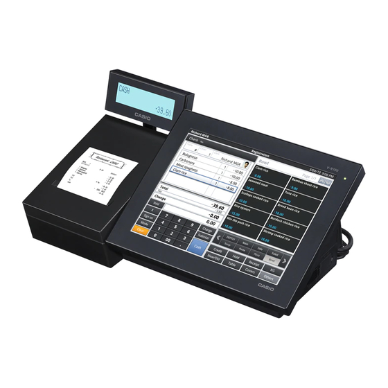
- Page 1 SERVICE MANUAL V-R100 (EX-841) OCT. 2011 Ver. 3 : Aug. 2013...
-
Page 2: Table Of Contents
V-R100 CONTENTS 1. SPECIFICATIONS ......................1 2. DISASSEMBLY ....................... 5 3. DIAGNOSTIC OPERATION ..................25 4. ERROR CODE LIST ..................... 37 5. HARDWARE ......................... 38 6. EXPLODED VIEW / PARTS LIST ................. 43... - Page 3 V-R100 CAUTION LAN CONNECTOR Ethernet (LAN) Connector: Not used to a telecommunication network CAUTION RISK OF EXPLOSION IF BATTERY IS REPLACED BY AN INCORRECT TYPE. DISPOSE OF USED BATTERIES ACCORDING TO THE INSTRUCTIONS. CAUTION “DO NOT INCINERATOR DISASSEMBLE; MAY EXPLODE OR RELEASE TOXIC MATERIALS.
-
Page 4: Specifications
V-R100 1. SPECIFICATIONS 1-1. Main Specifications Main Display Type 10.4 inch SVGA Color TFT LCD Resolution 800 × 600 Color * Max. 16,777,216 Backlight White LED Others Electric motor-driven tilt function (15 ° to 75 °) Touch Panel Type 4-wired resistive Size 10.4 inch... - Page 5 V-R100 1-2. System overview and I/O outlets [ Front ] [ Side ] [ Rear ] Printer cover Power switch Auto cutter unit Tilt switch Platen arm COM1 port Roll paper COM2 port Main LCD display with touch screen COM3 port...
- Page 6 V-R100 DISP-SW USB-SLOT SD-SLOT INIT-SW Reset-SW Boot-SW eMMC Boot SD Boot DISP-SW : Turns the main display on and off. Menu will be shown when it is pressed continuously. INIT-SW : Functions as [HOME] button. [Power OFF, Restart] menu will be displayed when pressed continously.
- Page 7 V-R100 1-3. Option List DEVICE NAME MODEL SPECIFICATION NOTE Slip printer SP-1300 Slip printer cable PRT-CB-8C EX-PRT-CB-8C Length 1.5 m Remote printer UP-400 EX-PRT-UNIT-10 Remote printer UP-370 EX-PRT-UNIT-11 PC cable PRL-CB-2 EX-PRL-CB-2 1-4. Drawer List Type Model Specification TAIWAN CANADA...
-
Page 8: Disassembly
V-R100 2. DISASSEMBLY 2-1. Cautions * Please note that the illustrations may differ from actual product due to design changes. * Please make a back-up copy of the clients’ data before disassembling. * There are several kinds of screws. Be sure to use the correct type of screws when reassembling. It is advisable to sort the screws as shown in the below after removing them. - Page 9 V-R100 2-2. Disassembling See the flowchart below for the order of disassembling main parts. A. CASE B. E840-IOC PCB / E840-COM PCB / E840-ETH-UNIT / DRAWER CABLE C. POWER-SW-ASSY / E840-E63 PCB D. AC-ADAPTOR / GEAR-BOX-ASSY E. SHAFT-SUBASSY / PS-COVER F.
- Page 10 V-R100 A. CASE A-1. Remove I/F-COVER and POP-COVER. I/F-COVER POP-COVER Caution for disassembly: If an optional screw is fixed on the I/F-COVER, remove it first. Optional screw A-2. Tilt up the main display then remove PS-LID. PS-LID Caution for assembly: Be cautious with the direction of PS-LID.
- Page 11 V-R100 A-3. Undo one screw from CABLE-CLAMP. A-4. Unplug POWER-CORD. POWER-CORD Screw (S2) A-5. Undo nine screws. Screws (S4) Screws (S2) A-6. Lift up the upper case slightly. Note: As it is connected with several cables, be careful not to cut the wires.
- Page 12 V-R100 A-8. Disconnect two connectors and raise the upper case. Note: As it is connected with several cables, be careful not to cut the wires. Connector Connector (AC-ADAPTOR) (POWER-SW) A-9. Disconnect five connectors and two FFCs. PR-PCB AC-ADAPTOR CONNECTOR REAR-LCD...
- Page 13 V-R100 A-10. Undo three screws and disconnect three ground wires. Screws (S3) Screw (S12) – 10 –...
- Page 14 V-R100 B. E840-IOC PCB / E840-COM PCB / E840-ETH-UNIT / DRAWER CABLE E840-ETH-UNIT Screws (S3) Connectors E840-COM PCB Screws (S12) Drawer Cable Screw (S12) Tighten with ground wire E840-IOC PCB B-1. E840-IOC PCB 1. Undo three screws. 2. Detach two connectors.
- Page 15 V-R100 C. POWER-SW-ASSY / E840-E63 PCB POWER-SW-ASSY Cable tie E840-E63 PCB Tape C-1. POWER-SW-ASSY 1. Remove cable tie. 2. Remove POWER-SW-ASSY. Caution for assembly: Assemble POWER-SW-ASSY with caution of its direction. Caution for assembly: Tie lead wires on POWER-SW-ASSY together with motor wires with a cable tie.
- Page 16 V-R100 D. AC-ADAPTOR / GEAR-BOX-ASSY Screws (S5) AC-ADAPTOR MO-SUPPORT Screws (S13) Screws (S13) GEAR-BOX-ASSY Screws (S5) D-1. MO-SUPPORT 1. Undo two screws and dismount MO-SUPPORT. D-2. AC-ADAPTOR 1. Undo three screws. 2. Remove the metal fittings and AC-ADAPTOR. Caution when replacing: When you replace the AC-ADAPTOR with a new one, Turn the AC cord around the ferrite core two times.
- Page 17 V-R100 E. SHAFT-SUBASSY / PS-COVER PS-COVER Screws (S7) Screws (S7) SHAFT-SUBASSY E-1. SHAFT-SUBASSY 1. Undo four screws. 2. Dismount SHAFT-SUBASSY. E-2. PS-COVER 1. Undo two screws. 2. Remove PS-COVER. – 14 –...
- Page 18 V-R100 F. PR-ASSY / PRINTER / E840-PR PCB / E840-E64 PCB F-1. Disengage one hooks and dismount PLATEN-ARM . PLATEN-ARM F-2. Disconnect one FFC and two connectors. F-3. Undo three screws and dismount PR-ASSY. Screw (S5) Screws (S5) Connectors Caution When Replacing With A New Unit: FFC When the FFC is replaced with a new one, form its shape as shown below.
- Page 19 V-R100 Caution When Replacing With A New Unit: PRINTER • The cutter comes with a new printer. (1) Remove EJECT-LEVER. (2) Undo two screws and remove the cutter. EJECT-LEVER Screws (S6) • The socket on new printer is not used so remove it.
- Page 20 V-R100 G. DP-CASE-ASSY G-1. Peel the double sided tape off the FFC. Double sided tape G-2. Remove DP-CASE-ASSY and DP-POLE by disengaging hooks. Hooks – 17 –...
- Page 21 V-R100 H. DISPLAY-ASSY / LCD-STAND DISPLAY-ASSY. H-1. Undo one screw and dismount Screw (S1) H-2. Disconnect the cable after removint CABLE-mask. CABLE-MASK – 18 –...
- Page 22 V-R100 Caution for assembly: Cable for DISPLAY-ASSY First, let the cable in a tube pass through the hole of the case. Then make two ground cables pass through the hole. Caution for assembly: Connectors Be cautious with connectors not to be disconnected.
- Page 23 V-R100 I. R-CASE-ASSY / HNG CHASSIS I-1. Remove CN-COVER and USB-COVER. I-2. Undo one screw and remove SHEET-COVER. I-3. Undo two screws and dismount BAT-COVER. USB-COVER Screws (S13) CN-COVER BAT-COVER Screw (S7) I-4. Undo six screws. SHEET-COVER I-5. Remove SD-COVER.
- Page 24 V-R100 I-7. Make sure that SD card is not inserted then remove R-CASE-ASSY. R-CASE-ASSY I-8. Undo four screws. I-9. Dismount HNG-CHASSIS. Screw (S9) Tighten with ground wire. Screws (S9) HNG-CHASSIS Caution for assembly: Make sure that seven connectors are securely connected then mount HNG-CHASSIS.
- Page 25 V-R100 J. E840-E61 PCB / E840-E62 PCB / BAT-BOX-SUBASSY E840-E61 PCB Connector E840-E61 PCB Connector E840-E61/E62 E840-E62 PCB Tape Connector BAT-BOX-SUBASSY BAT-BOX-SUBASSY J-1. E840-E61 PCB / E840-E62 PCB Peel off the tape. 2. Undo three screws (S11) affixing E840-E61 PCB.
- Page 26 V-R100 K. E840-1 PCB / DALLAS KEY E840-1 PCB Screw (S9) Screw (S9) Fixing two ground wires Connectors Screw (S9) Screw (S9) Tighten with ground wire. Tighten with ground wire. K-1. E840-1 PCB 1. Detach five connectors. 2. Undo four screws.
- Page 27 V-R100 L. F-CASE-ASSY (TOUCH-PANEL-ASSY) Screws (S10) Connectors Screw (S10) Tighten with ground wire. L-1. F-CASE-ASSY (TOUCH-PANEL-ASSY) 1. Detach two connectors. 2. Undo seven screws. 3. Dismount LCD-CHASSIS. LCD-CHASSIS LCD-UNIT F-CASE-ASSY (TOUCH-PANEL-ASSY) – 24 –...
-
Page 28: Diagnostic Operation
V-R100 3. DIAGNOSTIC OPERATION 3-1. Outline The operation is booted by diagnostic program copied SD card. 3-2. Preparation Prepare a SD card in which the diagnostic program is copied. 3-3. Booting 1. While the unit is powered off, slide Boot-SW to SD booting. - Page 29 V-R100 3-6. Diagnostic Items 1. Diagnostic menu and submenu DIAG MENU (Touch N to power-off) Display Version Number Set Log File Number Batch 1 Status Main LCD Initialize eMMC SD/eMMC/USB/LAN Menu SD/eMMC/USB/LAN MENU IOC Menu SD - vsd command Other Menu...
- Page 30 V-R100 2. Test items Test items Note Page DIAG MENU Display Version Number Displays version numbers of DIAG and IOC. For testing the touch panel For setting log file number Set Log File Number *Not used Tests clock, ROM, RAM and drawer automatically...
- Page 31 V-R100 DIAG MENU 0. Display Version Number [Function] Indicates the version numbers of DIAG and IOC. [Procedure] (1) Touch "0". Display shows the version numbers of DIAG and IOC. (2) By touching any position of the touch panel, display resumes DIAG MENU.
- Page 32 V-R100 4. Status [Function] Switches and sensors tests. [Procedure] (1) Touch "4" on the panel. Display indicates the screen shown below. Note: Push "INIT" switch lastly as it is for showing the tes results. PAPER Paper is in: SET Quit this screen by INIT-SWITCH...
- Page 33 V-R100 6. Initialize eMMC [Function] Initialize eMMC to enable read and write. [Procedure] Not used. SD/eMMC/USB/LAN MENU 1. SD - vsd command [Function] Checks SD card. [Procedure] (1) Touch "1" on the display panel. (2) After the test, display shows the test results and resumes SD/eMMC/USB/LAN MENU.
- Page 34 V-R100 4. LAN - lanp command [Function] Tests the communication with a LAN connected device. [Note] Any device (such as a PC or another cash register) can be used for the test as long as it's IP address is [192.168.1.10].
- Page 35 V-R100 3. COM1/2/3 Loopback [Function] Tests the COM ports. [Wiring] COM1/COM2/COM3 [Procedure] (1) Connect loopback connectors to all COM ports. (2) Touch "3" on the display panel. (3) COM port 1 is tested and the display shows the test result.
- Page 36 V-R100 6. Drawer #1 and #2 [Function] Tests drawers. [Note] There are two types of drawer cables. Long cable is for drawer 1 and short cable for drawer 2. [Procedure] (1) Connect the drawers 1 and 2 to the corresponding cables.
- Page 37 V-R100 Other MENU 1. Print LOG [Function] Prints test logs. [Procedure] (1) Touch "1" on the display panel. (2) Touch the log number to be printed. (3) After the printing, the display resumes Other MENU. 2. MAC ADDRESS Menu [Function] Display and correction of MAC address.
- Page 38 V-R100 Charge ON [Function] Executes charge-on test. [Procedure] (1) Touch "5" on the display panel. (2) After the test, display indicates the test result and resumes Other MENU. Charge OFF [Function] Executes charge-off test. [Procedure] (1) Touch "6" on the display panel.
- Page 39 V-R100 IPL eMMC [Function] Writes the diagnostic program in eMMC memory. [Procedure] Not used. command [Function] Executes DIAG command by the command entry. [Procedure] Not used. – 36 –...
-
Page 40: Error Code List
V-R100 4. ERROR CODE LIST 4-1. IOC Error Code List Rear Display Display Significance 0x00 FE_OK Correct 0x03 ERR_FLASH_ERASE Flash ROM erase error 0x04 ERR_FLASH_WRITE Flash ROM write error 0x06 ERR_FLASH_READ Flash ROM read error 0x07 ERR_COMM Communication error 0x09... -
Page 41: Hardware
V-R100 5. HARDWARE 5-1. Block Diagram 10.4 inch TFT-LCD 10.4 inch Touch Panel E840 -E62 E840-1 E840 -E61 Rear LCD E840-ETH E840-E22 AC Adaptor E840-IOC E840-COM E840-PR Thermal Printer Unit PWB E840-E63 PWB E840-E64 – 38 –... - Page 42 V-R100 5-2. System Diagram Enhanced Data Strage SD Card (SDHC) GPIO(WP/Detect) SD card I/F RGB 24 bit LVDS w/control SVGA Internal: 533 MHz DDR: 200 MHz GPIO (DDR2: 266 MHz) PWM(dimming ctrl.) LCD Backlight BUS: 66 MHz ASYNC BUS: 66 MHz...
- Page 43 V-R100 5-3. PCB E840-1 PCB – 40 –...
- Page 44 V-R100 E840-E61 PCB E840-E62 PCB E840-IOC PCB – 41 –...
- Page 45 V-R100 E840-E22 PCB E840-COM PCB E840-ETH PCB E840-E63 PCB E840-PRN PCB E840-E64 PCB – 42 –...
-
Page 46: Exploded View / Parts List
3. The numbers in item column correspond to the same numbers in drawing. 4. CASIO does not supply the spare parts without parts code. 5. Refer to the latest "Parts Price Code" at “PARTS FINDER” on the Casio Service WEB site (https://www.servicecasio.com). -
Page 47: Explode View
V-R100 6-1. EXPLODED VIEW <MAIN UNIT> DISPLAY-ASSY 3-15 3-11 2-11 3-11 3-16 2-13 2-15 3-14 3-16 2-14 2-10 3-10 3-17 E840-PRN PCB Printer 3-13 2-12 3-12 3-18 145 (-2/+5) mm – 44 –... - Page 48 V-R100 <TOUCH PANEL ASSY> 7-1 TOUCH-PANEL-ASSY 7-10 Dallas Model 7-16 7-1 TOUCH-PANEL-ASSY 7-15 7-17 7-18 7-19 7-14 7-13 7-12 7-11 – 45 –...
-
Page 49: Parts List
V-R100 6-2. PARTS LIST 1 V-R100-BD (DLS Europe) 3 V-R100-B (DI Europe) 5 V-R100-C (US/Canada) 7 V-R100-T (Taiwan) 2 V-R100-A (Australia) 4 V-R100-K (DI UK) 6 V-R100-DD (DLS UK) Q'ty Item Code No. Parts Name Specification 1. GENERAL-ASSY 10406975 COVER/PRINTER... - Page 50 V-R100 1 V-R100-BD (DLS Europe) 3 V-R100-B (DI Europe) 5 V-R100-C (US/Canada) 7 V-R100-T (Taiwan) 2 V-R100-A (Australia) 4 V-R100-K (DI UK) 6 V-R100-DD (DLS UK) Q'ty Item Code No. Parts Name Specification 4. PR-ASSY 10399634 PRINTER/THERMAL FTP-638MCL401-R 10413754 PCB ASSY/E840-PR...
- Page 51 V-R100 1 V-R100-BD (DLS Europe) 3 V-R100-B (DI Europe) 5 V-R100-C (US/Canada) 7 V-R100-T (Taiwan) 2 V-R100-A (Australia) 4 V-R100-K (DI UK) 6 V-R100-DD (DLS UK) Q'ty Item Code No. Parts Name Specification 8. R-CASE-ASSY 10410049 CASE/REAR RJE503837-001V02 10409533 BLIND/DALLAS...
-
Page 52: Drawer (Dl-2436/2814/2815) Expolode View
V-R100 6-3. DRAWER (DL-2436/2814/2815) EXPOLODE VIEW Bottom View DL-2436 DL-2814/2815 – 49 –... -
Page 53: Drawer (Dl-2436/2814/2815) Parts List
V-R100 6-4. DRAWER (DL-2436/2814/2815) PARTS LIST 1 DL-2814 2 DL-2815 3 DL-2436 Qt'y Item Code No. Parts Name Specification 10203171 RUBBER/FOOT CASE RJE500667-001V02 10167366 RUBBER/FOOT RJE501204-001V01 10230100 CABLE/FG RJE500104*001V03 10408590 METAL/TRAP RJE503885-001V01 10378459 ROLLER/DELRIN PB-19B1 52000106 RIVET 5X30 10203374 LOCK/CYLINDER... -
Page 54: Drawer (Dl-3624/3625) Expolode View
V-R100 6-5. DRAWER (DL-3624/3625) EXPOLODE VIEW – 51 –... -
Page 55: Drawer (Dl-3624/3625) Parts List
V-R100 6-6. DRAWER (DL-3624/3625) PARTS LIST 1 DL-3624 2 DL-3625 Qt'y Item Code No. Parts Name Specification 1041 4326 LOCK ASSY V081K00034K1 1041 4327 LOCK ASSY V081K00035K1 1907 9613 WIRE/FG ZD31670 1907 0223 CONNECTOR 1625-03PI 1902 7112 GROMET 1902 7076 SPRING... - Page 56 Ver.1 : Jan. 2012 • Caution for charging the battery for more than six hours is added. • Names and functions of Reset-SW and Boot-SW are added. (P3) • Reflected the modified points in assembly and disassembly procedures between sample and mass production units. (P5 to P24) • Correction of the EXPLODED VIEW (P44 to P45) • Correction of the PARTS LIST (P46 to P48) Ver.2 : Dec. 2012 • Model name change to V-R100. • Correction of the PARTS LIST (P46, P48) Ver.3 : Aug. 2013 • Correction of the PARTS LIST (P47) CASIO COMPUTER CO.,LTD. Overseas Service Division 6-2, Hon-machi 1-Chome Shibuya-ku, Tokyo 151-8543, Japan...
Need help?
Do you have a question about the V-R100 and is the answer not in the manual?
Questions and answers
Hi, my tables on hold have disappeared. Can I get them back
To restore disappeared tables on the Casio V-R100, first check for these possible issues:
1. E051 - Table Already Exists: If the table/check number already exists, use a different number.
2. E052 - Table Busy: If the table is in use on another terminal, wait until it is closed. If it remains busy incorrectly, reset the busy status using a special operation.
3. E053 - Table Not Opened: Confirm the check/table number is correct and re-enter it.
4. E054 - Out of Range: The current operator may not have access. Verify and enter a valid number.
If none of these solve the issue, consider restarting the cash register application using the "Restart" option on screen 300322.
This answer is automatically generated