
Related Manuals for Vaderstad Tempo F


Summary of Contents for Vaderstad Tempo F
- Page 1 Instructions Row Unit Tempo F, Tempo L, Tempo V Serial No. TPF0003318–, TPL0002039–, TPV0003133– 904162-en-gb; 16.10.2023 01 Original instructions...
- Page 2 ©Väderstad Holding AB, Väderstad, Sweden 2023 904162-en-gb; 16.10.2023...
- Page 3 Thank you for choosing Väderstad as your supplier! We hope that our products will increase your profitability and contribute to you having successful crops on your farm. Warm regards, The Stark Family...
-
Page 4: Table Of Contents
Contents General safety regulations.......1 Obligations and responsibilities ....1 Before using the machine ...... 1 How to read these instructions....1 Description of Safety Symbols ....1 Overview ...........3 General..........3 Control system ........3 Optional additions........ 3 Description of Row Unit ......5 Overview of row unit components ........ -
Page 5: General Safety Regulations
General safety regulations General safety regulations Obligations and responsibilities A. Reference (A) B. Reference (B) These instructions are to be regarded as for guidance only Information for which the order is important is indicated and entail no responsibility whatsoever on the part of using numbered action instructions. - Page 6 General safety regulations • Used to present information in the form of bullet points. The order in which the information is set out is not indicative of any particular order of precedence which must be followed. 904162-en-gb; 16.10.2023...
-
Page 7: Overview
Overview Overview General Assembly on delivery may only be carried out by personnel with basic technical know-how. The machines that are delivered directly from our factory should be assembled in accordance with the separate assembly instructions that are delivered with the machine. The following instructions assume that this assembly has already been completed. - Page 8 Overview Figure 2.6 Figure 2.8 Row cleaner, TPL 32 The row unit can be retrofitted with the following optional additions: A. Micro-granulate unit B. Seed sensor 16 or 22 mm C. Row cleaners D. Press wheel, on fixed arm 60 or 70 shore. Press wheel, on spring-suspended arm.
-
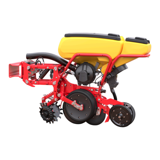
Page 9: Description Of Row Unit
Description of Row Unit Description of Row Unit Overview of row unit components Figure 3.2 The following types of wheel are available: Figure 3.1 1. Standard wheels are used for drilling medium to A. Seed hopper large-seed crops. B. Closing wheel 2. -
Page 10: Seed Meters
Description of Row Unit All the units have the same output rate, although there is 3.2.1 Construction of the Seed Meter the option to switch off each motor individually. A seed counter is fitted to each row unit. This is used to monitor the quantity and quality of the output. - Page 11 Description of Row Unit The outlet (H) contains a seed counter which identifies different seed discs in seed meters. Additional knock out the spacing and number of seeds passing through. The wheels can be stored in the seed meter cover (F). information is used to calculate skips and doubles, The sealing wheel (D) rolls along the outside of the seed amongst other things.
-
Page 12: Description Of Micro-Granulate
Description of Micro-granulate Description of Micro-granulate The row units can be equipped with a micro-granulate The bottom flaps can be set to four positions to be able to units. The micro-granulate unit can be used to apply adapt the gap (A) to suit different types of preparation. pesticides or an extra starter dose of fertiliser. -
Page 13: Micro-Granulate Coulters
Description of Micro-granulate Micro-granulate coulters Figure 4.5 The following types of coulter are available: A. Rigid micro-granulate coulter. B. Rigid micro-granulate coulter (closed base, rear opening). C. Spring-like micro-granulate coulter. D. Micro-granulate coulter with rubber nozzle. 904162-en-gb; 16.10.2023... -
Page 14: Settings For Seed Drilling
Settings for seed drilling Settings for seed drilling Seed 5.1.1 Seed disc in seed meter Figure 5.3 Ensure that the sliding hatch (A) of the seed meter is closed before starting removal of the seed disc in seed meter (B). This prevents the seed running out of the seed hopper. - Page 15 Settings for seed drilling Figure 5.6 5.1.1.2 Adjusting the seed disc in the seed meter Figure 5.8 2. Remove the two screws (A) to remove the seed grille (B). 3. Change the seed grille. Figure 5.7 1. Undo the pin on the motor shaft. There is an additional locking ring in the seed meter cover.
- Page 16 Settings for seed drilling 5.1.4 Setting the singulator Positions 1–9 are used to regulate the seed level in the seed meter when drilling. The position is indicated by a number of completely visible marks on the sliding hatch. In position 9, the sliding hatch is fully open and in position 0 (not visible) it is fully closed.
- Page 17 Settings for seed drilling 5.1.6.1 Setting a fixed press wheel 5.1.6.2 Setting a spring-suspended press wheel Figure 5.13 Fixed press wheel Figure 5.15 Spring-suspended press wheel 1. Remove the top screw (A) completely and undo the The spring-suspended press wheel is easily adjusted to bottom screw (B).
- Page 18 Settings for seed drilling In order to control the row unit pressure, it is possible to choose how often the seed hoppers are filled and how the weight transfer is set. For the drill to function correctly, the frame height must be adjusted so that the row unit linkage is parallel to the ground during operation.
- Page 19 Settings for seed drilling 5.1.8.2 Hydraulic weight transfer With fixed arm • The pressure on the closing wheels can be easily adjusted to five different settings using the spring (A). • The spring can also be pre-set to three different settings (B), the lowest of which gives the least force.
- Page 20 Settings for seed drilling 5.1.11 Moveable row cleaners, (optional) Tillage row cleaners are used to ensure good conditions for the row unit. If there are a lot of stones or clods on the surface, the row cleaner is used to remove these so that neither the coulter nor the gauge wheels are damaged by the unevenness of the surface.
-
Page 21: Micro-Granulate
Settings for seed drilling 5.1.11.2 Parked position, floating row cleaner Figure 5.28 Weight reduction The illustration shows the maximum weight reduction. Figure 5.30 Adjustment is made by moving the position of the spring in the upper linkage, the spring in the lower linkage must If you do not wish to use the row cleaner, put it into the be in the foremost position. - Page 22 Settings for seed drilling 2. Open the hatches of the output units and lift out the feed rollers (B). 3. Fit the new rollers and remount the motors. 4. Close the hatches of the output units. Figure 5.32 4. Open the plastic shutters (A) and check that the bottom flap is in the right position.
-
Page 23: Maintenance And Service
Maintenance and service Maintenance and service Safety when servicing To maintain the machine’s high level of quality and operational safety, use only Väderstad genuine spare parts. The warranty and any claims The machine must always be secured before any under it will become void if parts other than type of service or maintenance work is genuine parts are used. -
Page 24: Maintenance And Service Of The Row Unit
Maintenance and service Maintenance and service of the row unit Regularly clean the row unit of soil and dust, especially the area around the seed meter and the press-wheel. Check that no stones or clods are caught between the discs and the seed coulter. Check for play and wear in the joints and bearings, replace if necessary. - Page 25 Maintenance and service 6. Pull the end of the rubber stop outwards from the frame and turn it 90° downwards to vertical position. When the gauge wheel arm is in the long position, the rubber stop must always be in the horizontal position. Incorrect positioning of the rubber stop can cause mechanical damage to the inner edge of the gauge wheel and/or to the disc hub.
- Page 26 Maintenance and service Figure 6.10 Figure 6.12 Choose variant A or B. 2. Remove the centre bolt (B) in order to detach the 1. Remove the gauge wheel and seed disc on one side. wheel from the bracket. 2. Remove the pin that holds the seed coulter. 3.
- Page 27 Maintenance and service 6.3.6 Replacing the seed meter lid seals 6.3.7 Removal/installation of seed meter from/to the seed hopper A worn seal means that the pressure in the metering unit is not reaching 3.5 kPa (0,035 bar) as it should. Compare a new seal with the old one to determine the wear on the seal.
- Page 28 Maintenance and service 6.3.9 Cleaning and replacing the seed counter It is especially important to regularly clean the seed counter in dusty field conditions! When cleaning, do not use solvents as these can damage the photocell! Note that the seed tube is available in various widths - 16mm and 22mm.
- Page 29 Maintenance and service Checking for wear 4. Slide the singulator to the right and lift it away from the T-shaped locking lug. 5. Install the new singulator in the reverse order of the above. The gearwheel should be remounted so that the section without teeth is placed against the stop lug at the base of the singulator.
- Page 30 Maintenance and service 6.3.13 Replacing the electric motor Figure 6.25 5. Check that the arm on the motor axle (B) is in end Figure 6.27 position. Assemble the new singulator straight into the Seed Meter with the two holes (A) as guidance for 1.
-
Page 31: Maintenance And Service Of The Micro-Granulate Unit
Maintenance and service Never leave fertiliser in the machine for any length of time! Check the fertiliser hoses to ensure that they are empty. The micro-granulate output unit should be cleaned regularly and always when the season has come to an end. Figure 6.30 4. - Page 32 Maintenance and service In the bottom flap position 1, the play (A) between the output roller and the bottom flaps should be 0 mm. In the bottom flap position 2, the play (A) between the output roller and the bottom flaps should be 0,2 mm. The distance should be checked at the outer edge of the bottom flap.
- Page 33 904162-en-gb; 16.10.2023...
- Page 34 Väderstad AB SE-590 21 VÄDERSTAD Sweden Phone: +46 142- 820 00 www.vaderstad.com Where farming starts...
Need help?
Do you have a question about the Tempo F and is the answer not in the manual?
Questions and answers