
Related Manuals for DeDietrich HPI G Hybrid


Summary of Contents for DeDietrich HPI G Hybrid
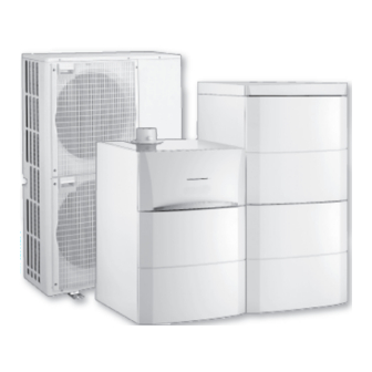
- Page 1 ADVANCE HPI G HYBRID User Guide Hybrid heat pump HPI G HYBRID 200 ASL HYBRID 4–8 200 ASL HYBRID 11–16 S U S T A I N A B L E C O M F O R T ®...
- Page 2 Dear Customer, Thank you very much for buying this appliance. Please read through the manual carefully before using the product, and keep it in a safe place for later reference. In order to ensure continued safe and efficient operation we recommend that the product is serviced regularly. Our service and customer service organisation can assist with this.
-
Page 3: Table Of Contents
Contents Contents Safety ................... . 5 General safety instructions . - Page 4 Contents Troubleshooting ..................47 Error codes .
-
Page 5: Safety
1 Safety Safety General safety instructions Danger This appliance is not intended for use by persons (including children) with reduced physical, sensory or mental capabilities, or lack of experience and knowledge, unless they have been given supervision or instruction concerning use of the appliance by a person responsible for their safety. - Page 6 1 Safety Important Insulate the pipes to reduce heat losses to a minimum. Caution The system must satisfy each point in the rules in force in the country that govern works and interventions in individual homes, blocks of flats or other buildings. Important Heating water and domestic water must not come into contact with each other.
- Page 7 1 Safety Caution The appliance is intended to be permanently connected to the domestic water mains network. Caution Respect the minimum and maximum water inlet pressure to ensure correct operation of the appliance: refer to the chapter Technical Specifications. Caution Draining the appliance: 1.
-
Page 8: Asl Hybrid
1 Safety Caution There must be no cut-off devices between the safety valve or unit and the domestic hot water tank. Electrical safety Caution A disconnection device must be fitted to the permanent pipes in accordance with the installation rules. Caution If a power cord comes with the appliance and it turns out to be damaged, it must be replaced by... -
Page 9: Recommendations
1 Safety Important The Installation Manual for the appliance is also available on our internet site. Recommendations Caution Install the heat pump's indoor module in a frost- free location. Important Only qualified persons are authorised to assemble, install and maintain the installation. Caution Maintenance work must be carried out by a qualified professional. - Page 10 1 Safety Important Remove the casing only to perform maintenance and repair work. Put the casing back in place after maintenance and repair work. Caution Give preference to the mode rather than switching off the system to leave the following functions running: Anti blocking of pumps Frost Protection...
-
Page 11: Specific Safety Instructions
1 Safety Specific safety instructions Warning Refrigerant fluid and pipes: Use only R410A refrigerant fluid to fill the installation. Use tools and pipe components especially designed for use with R410A refrigerant fluid. Use copper pipes deoxidised with phosphorus to carry the refrigerant fluid. Store the refrigerant connection pipes away from dust and humidity (risk of damage to the compressor). - Page 12 1 Safety Tab.2 Precautions for use First aid If inhaled: Evacuate the subject from the contaminated area and take him into the open air. If feeling unwell: call a doctor. In the event of contact with the skin: Treat frost injuries like burns. Rinse with copious amounts of tepid water, do not remove clothing (risk of adhesion to the skin).
-
Page 13: Liabilities
1 Safety Personal protection Respiratory protection: If ventilation is insufficient: AX type cartridge mask. In confined spaces: self-contained breathing apparatus. Hand protection: protective gloves in leather or nitrile rubber. Eye protection: safety glasses with side protection. Skin protection: clothing made principally of cotton Industrial hygiene: do not drink, eat or smoke at the place of work. -
Page 14: User's Liability
1 Safety Carry out initial commissioning and any checks necessary. Explain the installation to the user. If maintenance is necessary, warn the user of the obligation to check the appliance and keep it in good working order. Give all the instruction manuals to the user. 1.4.3 User's liability To guarantee optimum operation of the system, you... -
Page 15: About This Manual
2 About this manual About this manual General This manual is intended for the user of a 200 ASL HYBRIDhybrid system. Additional documentation This manual contains all settings and information on the 200 ASL HYBRID indoor module, as well as some information on the outdoor unit. For information on the boiler, refer to the instruction manuals provided with the boiler. -
Page 16: Asl Hybrid
2 About this manual Fig.2 Symbols used on the data plate 1 Information on the heat pump: Type of refrigerant fluid, maximum operating pressure, maximum output absorbed by the indoor module. 2 Information on the domestic hot water tank: Volume, maximum operating pressure and standby losses of the domestic hot water tank. -
Page 17: Technical Specifications
3 Technical specifications Technical specifications Homologations 3.1.1 Directives This product complies with the requirements of the following European Directives and Standards: Pressure Equipment Directive 2014/68/EU Low Voltage Directive 2014/35/EU Generic standard: EN 60335-1 Relevant standard: EN 60335-2-40 Electromagnetic Compatibility Directive 2014/30/EU Generic standards: EN 61000-6-3, EN 61000-6-1 Relevant Standard: EN 55014 This product conforms to the requirements of European Directive... - Page 18 3 Technical specifications Measure Unit AWHP 4.5 AWHP 6 AWHP 8 AWHP 11 AWHP 11 AWHP 16 AWHP 16 ment type MR-3 MR-2 MR-2 TR-2 MR-2 TR-2 Absorbed 0.90 1.38 1.82 2.45 2.45 3.47 3.47 electrical power Nominal wa 0.80 1.00 1.36 1.96...
-
Page 19: Domestic Hot Water Tank
3 Technical specifications Measure Unit AWHP 4.5 AWHP 6 AWHP 8 AWHP 11 AWHP 11 AWHP 16 AWHP 16 ment type MR-3 MR-2 MR-2 TR-2 MR-2 TR-2 R410A re 2.714 2.923 6.680 9.603 9.603 9.603 9.603 frigerant Refrigerant inch 1/4 - 1/2 1/4 - 1/2 3/8 - 5/8 3/8 - 5/8... -
Page 20: Weight
3 Technical specifications 3.2.3 Weight Tab.11 Indoor module Indoor module Unit 200 ASL HYBRID 4–8 200 ASL HYBRID 11–16 Weight empty Total weight with water Refer to the boiler manual to calculate the total weight of the indoor module combined with the boiler. Tab.12 Outdoor unit Outdoor... - Page 21 3 Technical specifications Product name 200 ASL Hybrid 200 ASL Hybrid 4.5MR 6MR-3 + AGC 15 + AGC 25 = -7°C COPd 1.64 1.86 COPd = +2 °C 3.46 3.40 COPd = +7 °C 4.96 4.52 COPd = +12 °C 7.35 6.70 COPd...
- Page 22 3 Technical specifications Tab.14 Technical parameters for heat pump combination heaters (parameters declared for medium-temperature application) Product name 200 ASL 200 ASL 200 ASL Hybrid 8MR-2 Hybrid 11MR-2 Hybrid 16MR-2 + AGC 25 + AGC 25 + AGC 25 Air-to-water heat pump Water-to-water heat pump Brine-to-water heat pump Low-temperature heat pump...
-
Page 23: Circulating Pump
3 Technical specifications Product name 200 ASL 200 ASL 200 ASL Hybrid 8MR-2 Hybrid 11MR-2 Hybrid 16MR-2 + AGC 25 + AGC 25 + AGC 25 Heating water operating limit temperature WTOL °C Electrical power consumption Off mode 0.009 0.009 0.009 Thermostat-off mode 0.049... - Page 24 3 Technical specifications Fig.4 Pressure available 1 Available pressure in metres of water column (mWc) 2 Water flow rate in cubic metres per hour (m 3 Available pressure for 4 to 8 kW outdoor units 4 Available pressure for the 11 and 16 kW outdoor units MW-2000147-2 200 ASL HYBRID 7613348 - v06 - 10122018...
-
Page 25: Description Of The Product
4 Description of the product Description of the product General description The heat pump comprises: A 200 ASL HYBRID indoor module, including a domestic hot water tank. A condensing gas boiler, installed on top of or beside the indoor module. A reversible outdoor unit for energy production in heating or cooling mode. -
Page 26: Main Components
4 Description of the product Fig.5 General operating principle MW-6000391-1 1 Evaporator (fin battery in the outdoor unit) 5 Electrical energy 2 Compressor 6 Heating water 3 Condenser (plate exchanger in the indoor module) 7 Energy flow 4 Electronic expansion valve 8 Heat recovered from the environment Main components Fig.6... -
Page 27: Description Of The Control Panel
4 Description of the product Fig.7 Position of the PCBs 1 Heating generator control system PCB (EHC-02) 2 Interface PCB for the outdoor unit MW-5000400-1 Description of the control panel All of the information needed to manage the hybrid heat pump is displayed on the boiler's control panel. - Page 28 4 Description of the product Status of the compressor Fig.11 Indicator Steady symbol: compressing running Flashing symbol: compressor off, run request pending < AUTO Installation pressure Fig.12 Pressure indicator: hydraulic pressure sensor connected Steady symbol: hydraulic pressure sufficient Flashing symbol: hydraulic pressure insufficient Hydraulic pressure level 0.9 to 1.1 bar <...
- Page 29 4 Description of the product Fig.16 Steady symbol: permanent override Flashing symbol: temporary override < AUTO AUTO AUTO AUTO AUTO AUTO AUTO AUTO AUTO Information about the circuits Fig.17 Domestic hot water production running Three-way valve connected: : 3-way valve open <...
-
Page 30: Operation
5 Operation Operation General Once the indoor module has been connected to the boiler, the unit is managed from the boiler control panel. No action need be taken directly on the indoor module. The boiler control panel: displays every item of information on the hybrid heat pump as a whole (boiler, indoor module, outdoor unit) is used to make the settings required for the hybrid heat pump to run. -
Page 31: Start-Up
5 Operation Start-up 1. Switch on the outdoor unit and the indoor module simultaneously. 2. The hybrid heat pump begins its start-up cycle. If the start-up cycle runs normally, an automatic venting cycle is initiated. Otherwise, an error message is displayed. Installation shutdown Important If the heating system is not due to be used for a long period of... -
Page 32: Settings
6 Settings Settings List of parameters 6.1.1 User Level Menus available at User level: Access keys Menus TEMPERATURE MODE Operating mode Domestic hot water #MEASURES #CHOICE TIME PROG. #TIME PROGRAM #SETTING #ANNUAL PROG #TIME .DAY TEMPERATURE menu - User Level Certain parameters are displayed: according to certain system configurations, according to the options, circuits or sensors actually connected. - Page 33 6 Settings Parameters Description Factory setting Customer setting SWIMMING P.T.C Desired temperature for the swimming pool connected to cir 20°C cuit C. Can be set from 5 to 39°C. WATER T.NIGHT Desired domestic hot water temperature in the domestic hot 10°C water circuit.
- Page 34 6 Settings Domestic Hot Water menu - User Level Tab.17 Domestic Hot Water menu ( Parameters Description Factory setting AUTOMATIC Domestic hot water production is determined by the setting in the #TIME PROGRAM menu. COMFORT 7/7 Domestic hot water production is forced at all times: seven days a week. Current time + 1 hour COMFORT ->...
- Page 35 6 Settings Parameters Description Unit NB IMPULS. Number of burner start-ups (cannot be reinitialised). The meter is incremented by 8 every 8 start-ups. RUNTIME Number of hours' burner operation (cannot be reinitialised). The meter is incremented by 2 every 2 hours. IN 0-10V Voltage on the input 0-10V CTRL...
- Page 36 6 Settings Parameters Comfort period / Loading enabled Factory setting Customer setting PROG P4 A Monday: 6:00-8:00 / 11:00-13:30 / 16:00-22:00 PROG P4 B Tuesday: 6:00-8:00 / 11:00-13:30 / 16:00-22:00 PROG P4 C Wednesday: 6:00-8:00 / 11:00-13:30 / 16:00-22:00 Thursday: 6:00-8:00 / 11:00-13:30 / 16:00-22:00 Friday: 6:00-8:00 / 11:00-13:30 / 16:00-22:00...
- Page 37 6 Settings Parameters Description Factory setting Customer setting ANTIFR.ROOM A Room temperature at which frost protection on circuit A is ac 6°C tivated. Can be set from 0.5 to 20 °C. CALIBR.ROOM A Calibration of the room temperature sensor on circuit A. Room tempera...
- Page 38 6 Settings Parameters Description STOP N 7 BEG.DATE N 07 BEG.MONTH N 07 END DATE N 07 END MONTH N 07 STOP N 8 BEG.DATE N 08 BEG.MONTH N 08 END DATE N 08 END MONTH N 08 STOP N 9 BEG.DATE N 09 BEG.MONTH N 09 END DATE N 09...
- Page 39 6 Settings Tab.27 STOP N 4 Parameters Description Factory setting Customer setting BEG.DATE N 04 Shut-down start date: can be set from 1 to 31 BEG.MONTH N 04 Shut-down start month: can be set from 1 to 12 END DATE N 04 Shut-down end date: can be set from 1 to 31 END MONTH N 04 Shut-down end month: can be set from 1 to 12...
-
Page 40: User Settings
6 Settings #TIME .DAY menu - User Level Tab.34 Menu #TIME .DAY Parameters Description Factory setting Customer setting HOURS Hours. Can be set from 0 to 23. MINUTE Minutes. Can be set from 0 to 59. Day of the week. Can be set from Monday to Sunday. -
Page 41: Setting The Set Point Temperatures
6 Settings Selecting the Operating Mode Forcing domestic hot water production Selecting a Timer Program Customising a timer program Calibrating the sensors Setting the contrast and brightness of the display Setting the Time and Date 6.2.1 Setting the Set Point Temperatures Fig.22 Accessing the set point temperature 1. -
Page 42: Selecting A Timer Programme
6 Settings 6.2.4 Selecting a timer programme 1. Go to the User level by pressing the key. 2. Select the #CHOICE TIME PROG. menu by turning the settings button. 3. Confirm the selection by pressing the settings button. Important Go back to the previous display by pressing the key. -
Page 43: Calibrating The Sensors
6 Settings Fig.26 Selecting/deselecting a day 9. Select or deselect a day by pressing the settings button once or twice. The symbol is displayed for selection. The symbol is displayed for deselection. PROG P2 C We Th 10. Confirm one or more days by pressing the settings button. "Select the days to program"... -
Page 44: Setting The Contrast And Brightness Of The Display
6 Settings 6.2.7 Setting the contrast and brightness of the display 1. Go to the User level by pressing the key. 2. Select the #SETTING menu by turning the settings button. 3. Confirm the selection by pressing the settings button. Important Go back to the previous display by pressing the key. -
Page 45: Maintenance
7 Maintenance Maintenance General Maintenance operations are important for the following reasons: To guarantee optimum performance. To extend the life of the equipment. To provide an installation which offers the user optimum comfort over time. Caution Maintenance work must be carried out by a qualified professional. Danger Before any work, switch off the mains electricity to the heat pump and the hydraulic or electrical back-up if connected. -
Page 46: Cleaning The Casing
7 Maintenance Cleaning the casing 1. Clean the outside of the appliance using a damp cloth and a mild detergent. 200 ASL HYBRID 7613348 - v06 - 10122018... -
Page 47: Troubleshooting
8 Troubleshooting Troubleshooting Error codes 8.1.1 Error messages If an error occurs, the control panel displays an error message and the corresponding code. 1. Make a note of the code displayed. The code is important for the correct and rapid diagnosis of the type of error and for any technical assistance that may be needed. -
Page 48: Dxx Type Errors
8 Troubleshooting 1. Press the key for 10 seconds to access the After Sales Service level. 2. Select the #MESSAGE HISTORIC menu by turning the settings button. Fig.31 3. Confirm the selection by pressing the settings button. Important Go back to the previous display by pressing the key. -
Page 49: Bxx Type Errors
8 Troubleshooting Messages Code Description ROOM S.C FAIL. Room temperature sensor error on circuit C: circuit C operates with no influence from the room temperature sensor on circuit C: Contact the professional responsible for maintenance of the heat pump MC COM.FAIL Interruption in communication between the SCU PCB and the boiler radio module: Contact the professional responsible for maintenance of the heat pump ST.TANK S.FAIL... -
Page 50: Fault History
8 Troubleshooting Messages Code Description BL.PRES.SENS.OPEN Error on the water pressure sensor or sensor missing. Contact the professional responsible for maintenance of the heat pump BL.PRES.SENS.SHORT B06 Error on the water pressure sensor or sensor missing. Contact the professional responsible for maintenance of the heat pump BL.PRES.SENS.MISS Error on the water pressure sensor or sensor missing. -
Page 51: Lxx Type Errors
8 Troubleshooting 2. Select the #DEFAULT HISTORIC menu by turning the settings button. Fig.33 3. Confirm the selection by pressing the settings button to access the list of the last ten faults. Important OUTL S.B FAIL. 29/08 DHW S.FAILURE 13/07 Go back to the previous display by pressing the key. - Page 52 8 Troubleshooting Problems Probable causes Corrections There is no domestic The domestic hot water Increase the value of parameter hot water. set point temperature is too low. The domestic hot water Activate the domestic hot water mode. mode is deactivated. The energy-saving shower Clean the shower head;...
-
Page 53: Decommissioning And Disposal
9 Decommissioning and disposal Decommissioning and disposal Decommissioning procedure To decommission the heat pump temporarily or permanently: 1. Contact the installer. Disposal and recycling Fig.35 Warning Removal and disposal of the heat pump must be carried out by a qualified professional in accordance with prevailing local and national regulations. -
Page 54: 10 Environmental
10 Environmental 10 Environmental 10.1 Energy savings Energy-saving advice: Do not block ventilation outlets. Do not cover the radiators. Do not hang curtains in front of the radiators. Install reflective panels behind the radiators to prevent heat losses. Insulate the pipes in rooms that are not heated (cellars and lofts). Close the radiators in rooms not in use. -
Page 55: 11 Warranty
11 Warranty 11 Warranty 11.1 General We would like to thank you for buying one of our appliances and for your trust in our product. In order to ensure continued safe and efficient operation, we recommend that the product is regularly inspected and maintained. Your installer and our service department can assist with this. -
Page 56: 12 Appendix
12 Appendix 12 Appendix 12.1 Product fiche Tab.39 Product sheet for heat pump combination heaters 200 ASL Hybrid 200 ASL Hybrid 4.5MR 6MR-2 / 200 ASL + AGC 15 Hybrid 6MR-3 + AGC 25 Space heating - Temperature application Water heating - Declared load profile Seasonal space heating energy efficiency class under average climate conditions Water heating energy efficiency class under average climate conditions... -
Page 57: Product Fiche - Temperature Controls
12 Appendix 200 ASL 200 ASL 200 ASL Hybrid 8MR-2 Hybrid Hybrid + AGC 25 11MR-2 16MR-2 + AGC 25 + AGC 25 Seasonal space heating energy efficiency under average cli mate conditions Water heating energy efficiency under average climate condi 106.00 106.00 106.00... - Page 58 12 Appendix Fig.36 Package fiche for medium-temperature heat pumps indicating the space heating energy efficiency of the package Seasonal space heating energy effi ciency of heat pump ‘I’ Temperature control Class I = 1%, Class II = 2%, Class III = 1.5%, Class IV = 2%, Class V = 3%, Class VI = 4%, from fi...
- Page 59 12 Appendix Tab.42 Weighting of medium temperature heat pumps II, package without hot water storage tank II, package with hot water storage tank Prated / (Prated + Psup) (1)(2) 1.00 1.00 0.70 0.63 0.45 0.30 0.25 0.15 0.15 0.06 0.05 0.02 0.02 ≥...
- Page 60 12 Appendix 200 ASL HYBRID 7613348 - v06 - 10122018...
- Page 61 12 Appendix 7613348 - v06 - 10122018 200 ASL HYBRID...
- Page 62 12 Appendix 200 ASL HYBRID 7613348 - v06 - 10122018...
- Page 63 © Copyright All technical and technological information contained in these technical instructions, as well as any drawings and technical descriptions supplied, remain our property and shall not be multiplied without our prior consent in writing. Subject to alterations.
- Page 64 57, rue de la Gare - F-67580 Mertzwiller SERVICE CONSOMMATEURS 03 88 80 27 00 0,15 € / min 0 825 120 520 03 88 80 27 99 www.dedietrich-thermique.fr 000 «БДP T » VAN MARCKE 129164, Россия, г. Москва Weggevoerdenlaan 5 Зубарев...
Need help?
Do you have a question about the HPI G Hybrid and is the answer not in the manual?
Questions and answers