Table of Contents
Advertisement
Advertisement
Table of Contents

Subscribe to Our Youtube Channel
Related Manuals for Pentair Hypro 9915-DP803


Summary of Contents for Pentair Hypro 9915-DP803
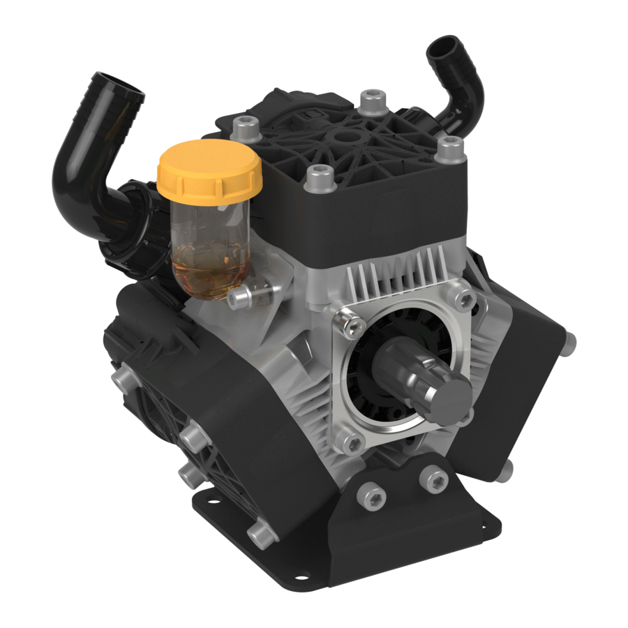
- Page 1 DIAPHRAGM PUMPS INSTALLATION AND OPERATION MANUAL pentair.com...
-
Page 2: Table Of Contents
TABLE OF CONTENTS Safety Information ....................................3 General Information ....................................5 Installation and Operations ................................... 6 Maintenance ......................................8 Low Pressure 15 Bar Performance & Specifications ..............................10 Installation ....................................11 Replacement Parts List ................................12 Medium Pressure 20-40 Bar Performance & Specifications ..............................18 Installation ....................................20 Replacement Parts List ................................ -
Page 3: Safety Information
SAFETY INFORMATION Save these instructions: This manual contains important Personal Safety: instructions that should be followed during installation, Wear safety glasses at all times when working with pumps. operation, and maintenance of the product. Keep work area clean, uncluttered and properly lighted. ... - Page 4 SAFETY INFORMATION Do not pump at pressures higher than the maximum HAZARDOUS SUBSTANCE ALERT recommended pressure. Always drain and flush pump before servicing or Operate the pump between a temperature ranges of 45° to disassembling for any reason (see instructions). ...
-
Page 5: General Information
GENERAL INFORMATION DESCRIPTION AND USES MISUSES Hypro Diaphragm pumps are intended for creating or boosting Hypro centrifugal pumps are designed to operate effectively dynamic pressure for non-food purposes with clean and within the specified speed, pressure and environmental ranges. approved fluids in a watery solution which are compatible with Going outside of these ranges will void the warranty and could the materials of the pump at temperatures between 45°... -
Page 6: Installation And Operations
INSTALLATION AND OPERATION PUMP PLUMBING SHAFT ADAPTER KIT INSTALLATION Use only pipe, fittings, accessories, hose, etc. rated for the Order the appropriate shaft kit according to the chart on Spec maximum pressure rating of the pump. Sheet. Always mount pump with oil sight tube in upright position Mount shaft adapter (Ref. - Page 7 INSTALLATION AND OPERATION OPERATION First back out the pressure regulator adjustment knob to zero. Before start up check that oil is halfway up to the clear Then rotate the Pressure Release knob to Pressure arrow oil sight tube. If necessary, fill to the correct level with direction.
-
Page 8: Maintenance
MAINTENANCE MAINTENANCE SCHEDULE REGULAR SERVICE PERIOD Every 3 Every 6 First month Performed at every indicated month or operating hour interval, First Use Each Use months or months or or 40 hours whichever comes first. 500 hours 1000 hours Check Level Crankcase Oil Replace Check Level... - Page 9 MAINTENANCE DIAPHRAGM REPLACEMENT Change diaphragms every 500 hours or three months, whichever comes first. Drain oil from crankcase as instructed previously. Remove pump head bolts and heads. Remove the bolt securing the diaphragm (See Figure 4). Remove the old diaphragm and the washer (See Figure 4). Install a new diaphragm.
- Page 10 DIAPHRAGM PUMP: LOW PRESSURE RANGE 15BAR "Max. Flow "Max. Pressure "Max. Speed "Power No. of Model Number USGPM [LPM]" PSI [BAR]" RPM" HP [KW]" Diaphragm 9915-DP803 21.7 [82] 218 [15] 3.2 [2.4] "Max. Flow "Max. Pressure "Max. Speed "Power No. of Model Number USGPM [LPM]"...
-
Page 11: Low Pressure 15 Bar
LOW PRESSURE 15 BAR PERFORMANCE AND SPECIFICATIONS CONTROL UNIT KIT INSTALLATION For all discharge hoses, use hose with an operating pressure The control units are designed for control of pressure and flow rating equal to or greater than the maximum pressure rating of rate. - Page 12 LOW PRESSURE 15 BAR REPLACEMENT PARTS FIGURE 7: MODEL DP803 L-1600 (04/01/21)
- Page 13 LOW PRESSURE 15 BAR REPLACEMENT PARTS TORQUE CHART DP803 9915-KIT2004 REF. No. Qty. ft.Lbs KIT DIAPHRAGM DP803 DP1003 REF. No. DESCRIPTION QTY. 18.5 PRE-SET DURAMAX PISTON 14.8 DIAPHRAGM "5 "3.7 O-RING 3.53X28.17 (LOXEAL 55-14)" (LOXEAL 55-14)" 32.5 9915-KIT2104 KIT SERVICE VALVE DP803 DP1003 32.5 REF.
- Page 14 LOW PRESSURE 15 BAR REPLACEMENT PARTS FIGURE 8: MODEL DP1003 L-1600 (04/01/21)
- Page 15 LOW PRESSURE 15 BAR REPLACEMENT PARTS TORQUE CHART DP1003 9915-KIT2004 REF. No. Qty. ft.Lbs KIT DIAPHRAGM DP803 DP1003 REF. No. DESCRIPTION QTY. 18.5 PRE-SET DURAMAX PISTON DIAPHRAGM (LOXEAL 55-14) (LOXEAL 55-14) O-RING 3.53X28.17 32.5 9915-KIT2104 32.5 KIT SERVICE VALVE DP803 DP1003 29.5 REF.
- Page 16 LOW PRESSURE 15 BAR REPLACEMENT PARTS FIGURE 9: MODEL DP2505 L-1600 (04/01/21)
- Page 17 LOW PRESSURE 15 BAR REPLACEMENT PARTS TORQUE CHART DP2505 9915-KIT2005 REF. No. Qty. ft.Lbs KIT DIAPHRAGM DP2505 REF. No. DESCRIPTION QTY. 18.4 PRE-SET DURAMAX PISTON 14.8 DIAPHRAGM O-RING 4.5x40 VITON (LOXEAL 24-18)" (LOXEAL 24-18)" 29.5 9915-KIT2105 16.3 KIT SERVICE VALVE DP2505 16.3 REF.
- Page 18 DIAPHRAGM PUMP: MEDIUM PRESSURE RANGE 20 - 40BAR "Max. Flow "Max. Pressure "Max. Speed "Power No. of Model Number USGPM [LPM]" PSI [BAR]" RPM" HP [KW]" Diaphragm 9915-DP252 9915-DP252GRGI 6.3 [24] 290 [20] 3450 1.4 [1.1] 3450 9915-DP252GRGI58 "Max. Flow "Max.
- Page 19 MEDIUM PRESSURE 20-40 BAR PERFORMANCE AND SPECIFICATIONS DRIVE OPTIONS Order the appropriate shaft adapter kit or gear reduction unit Control Units: Control units are available for easy flow and for the drive option requirements. Refer to the adjoining chart pressure control of your sprayer system. These units include for proper selection.
-
Page 20: Installation
MEDIUM PRESSURE 20-40 BAR INSTALLATION INSTALLATION INSTRUCTIONS FOR GEAR REDUCTION KIT The 9915-KIT1105 gear reducer is designed for direct mounting 9915-KIT1103 (REFER TO FIGURE 10) the diaphragm pumps (listed in chart on page 19) onto an 8 hp gasoline engine with a flange mounting and 1” solid shaft. NOTE: Hypro recommends a blue thread locking compound on all threaded fasteners that do not require lock washers. -
Page 21: Installation
MEDIUM PRESSURE 20-40 BAR INSTALLATION FIGURE 10: MODEL 9915-KIT1103 FIGURE 11: MODEL 9915-KIT1105 L-1600 (04/01/21) - Page 22 MEDIUM PRESSURE 20-40 BAR INSTALLATION CONTROL UNIT KIT INSTALLATION The control units are designed for control of pressure and flow For all discharge hoses, use hose with an operating pressure rate. Use appropriate model (as specified in chart on page 19) rating equal to or greater than the maximum pressure rating of to mount on particular pump model and pressure/flow ranges.
- Page 23 MEDIUM PRESSURE 20-40 BAR INSTALLATION PRESSURE REGULATOR ADJUSMENT KNOB OUTLET PRESSURE REGULATOR ADJUSMENT KNOB FIGURE 12: MODEL 9915-KIT1001 OUTLET PRESSURE REGULATOR ADJUSMENT OUTLET KNOB FIGURE 13: MODEL 9915-KIT1002 & 9915-KIT1008 PRESSURE REGULATOR OUTLET ADJUSMENT KNOB FIGURE 14: MODEL 9915-KIT1003 L-1600 (04/01/21)
- Page 24 MEDIUM PRESSURE 20-40 BAR REPLACEMENT PARTS FIGURE 15: MODELS 9915-DP252, 9915-DP302 L-1600 (04/01/21)
- Page 25 MEDIUM PRESSURE 20-40 BAR REPLACEMENT PARTS 9915-KIT2001 TORQUE CHART DP252 DP302 REF. No. Qty. ft.Lbs KIT DIAPHRAGM DURAMAX DP252 DP302 REF. No. DESCRIPTION QTY. PRE-SET DURAMAX PISTON DIAPHRAGM (STD.) DAMPENER DIAPHRAGM O-RING D.2.62X15.54 O-RING D.2.62X22.22 O-RING D.2.62X26.65 29.5 9915-KIT2101 KIT SERVICE VALVE DP252 DP302 REF.
- Page 26 MEDIUM PRESSURE 20-40 BAR REPLACEMENT PARTS FIGURE 16: MODEL 9915-D303, 9915-D403 L-1600 (04/01/21)
- Page 27 MEDIUM PRESSURE 20-40 BAR REPLACEMENT PARTS TORQUE CHART D303, D403 9915-KIT2002 REF. No. Qty. ft.Lbs KIT DIAPHRAGM D303, D403 REF. No. DESCRIPTION QTY. DURAMAX PISTON DIAPHRAGM VALVE SEAL 16.2 16.2 16.2 9915-KIT2102 Tolerance on Torque value: +0/-10% KIT SERVICE VALVE D303, D403 REF.
- Page 28 MEDIUM PRESSURE 20-40 BAR REPLACEMENT PARTS FIGURE 17: MODEL 9915-D503 L-1600 (04/01/21)
- Page 29 MEDIUM PRESSURE 20-40 BAR REPLACEMENT PARTS TORQUE CHART D503 9915-KIT2008 KIT DIAPHRAGM D503 REF. No. Qty. ft.Lbs REF. No. DESCRIPTION QTY. 16.2 DURAMAX PISTON DIAPHRAGM O-RING 2.62X18.72 32.5 32.5 9915-KIT2108 32.5 KIT SERVICE VALVE D503 Tolerance on Torque value: +0/-10% REF.
- Page 30 MEDIUM PRESSURE 20-40 BAR REPLACEMENT PARTS FIGURE 18: MODEL 9915-DP503 L-1600 (04/01/21)
- Page 31 MEDIUM PRESSURE 20-40 BAR REPLACEMENT PARTS TORQUE CHART DP503 9915-KIT2003 KIT DIAPHRAGM DP503 REF. No. Qty. ft.Lbs REF. No. DESCRIPTION QTY. PRE-SET DURAMAX PISTON DIAPHRAGM 32.4 O-RING 2.62X18.72 16.2 O-RING 2.62X20.24 32.4 16.2 9915-KIT2103 KIT SERVICE VALVE DP503 REF. No. DESCRIPTION QTY.
- Page 32 DIAPHRAGM PUMP: HIGH PRESSURE RANGE 50 BAR "Max. Flow "Max. Pressure "Max. Speed "Power No. of Model Number USGPM [LPM]" PSI [BAR]" RPM" HP [KW]" Diaphragm 9915-D1063 27.9 [106] 725 [50] 13.9 [10.4] "Max. Flow "Max. Pressure "Max. Speed "Power No.
- Page 33 HIGH PRESSURE 50 BAR INSTALLATION CONTROL UNIT KIT INSTALLATION The control units are designed for control of pressure and flow Always wear safety goggles when working with spring-loaded fasteners or devices. rate. Use appropriate model (as specified in chart on page 32) to use with particular pump model and pressure/flow ranges.
- Page 34 HIGH PRESSURE 50 BAR REPLACEMENT PARTS FIGURE 20: MODEL 9915-D1063 L-1600 (04/01/21)
- Page 35 HIGH PRESSURE 50 BAR REPLACEMENT PARTS TORQUE CHART D1063 9915-KIT2006 REF. No. Qty. ft.Lbs KIT DIAPHRAGM D1063 32.5 REF. No. DESCRIPTION QTY. 16.2 DESMOPAN PISTON DIAPHRAGM NBR BALLASTER DIAPHRAGM 18.5 O-RING DIA.2,62x22,22 16.2 32.5 72.2 Tolerance on Torque value: +0/-10% 9915-KIT2106 KIT SERVICE VALVE D1063 REF.
- Page 36 HIGH PRESSURE 50 BAR REPLACEMENT PARTS FIGURE 21: MODEL 9915-D1504 L-1600 (04/01/21)
- Page 37 HIGH PRESSURE 50 BAR REPLACEMENT PARTS TORQUE CHART D1504 9915-KIT2007 REF. No. Qty. ft.Lbs KIT DIAPHRAGM D1504 16.2 REF. No. DESCRIPTION QTY. 16.2 DESMOPAN PISTON DIAPHRAGM NBR BALLASTER DIAPHRAGM 32.5 O-RING DIA.2.62x22.22 18.5 79.7 32.5 16.2 9915-KIT2107 Tolerance on Torque value: +0/-10% KIT SERVICE VALVE D1504 REF.
-
Page 38: Troubleshooting
TROUBLESHOOTING SYMPTOM POSSIBLE CAUSE CORRECTIVE ACTION Remove valve and check for debris. One or more valves are seating improperly. Remove any debris found. Examine the valve seating and clean them. The pump does not draw water Examine and clean the suction line. Suction line is plugged or collapsed. - Page 39 TROUBLESHOOTING Examples of diaphragms failures & causes CIRCULAR FRACTURE ON PISTON SIDE OF DIAPHRAGM WHICH IS SAME DIAMETER AS PISTON POSSIBLE CAUSES: BLOW-BY BETWEEN PISTON AND SLEEVE 2. SUCTION HAS TOO MUCH PRESSURE (EXCESSIVE HEAD) 3. LOW PUMP RPM 4. DELIVERY VALVE NOT SEALING 5.
-
Page 40: Warranty
Fax: 800-323-6496 Pentair trademarks and logos are owned by Pentair or its affiliates. Third party registered and unregistered trademarks and logos are the property of their respective owners. Because we are continuously improving our products and services, Pentair reserves the right to change specifications without prior notice. Pentair is an equal opportunity employer.
Need help?
Do you have a question about the Hypro 9915-DP803 and is the answer not in the manual?
Questions and answers