Advertisement
Quick Links
8T49N1012 Evaluation Board
Introduction
The 8T49N1012 evaluation board user guide is intended to help the user power-up and quick-start the 8T49N1012 evaluation
board. The scope of the user guide is limited to the physical connectivity of the board and does not address the programming
section of it.
This guide will model two set-ups: Set-up 1 will use a clock generator as input and Set-up 2 will use a crystal as input source.
Set-up 1:
•
CLK/nCLK will be used as input
•
Q0/nQ0 will be used as output
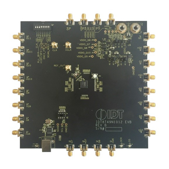
Board Overview
Use
Figure 1
to identify the power supply jacks, input and output SMA connectors, USB connector, crystal, power selection
jumpers, dip switch, device under test, EEPROM, Reset button, CLK/nCLK Inputs and Ref_Out.
Figure 1. 8T49N1012 Evaluation Board Top View
MARCH 30, 2016
Set-up 2:
•
OSCI/OSCO will be used as input
•
Q0/nQ0 will be used as output
1
USER GUIDE
©2016 Integrated Device Technology, Inc.
Advertisement

Subscribe to Our Youtube Channel
Related Manuals for Renesas 8T49N1012


Summary of Contents for Renesas 8T49N1012
- Page 1 Introduction The 8T49N1012 evaluation board user guide is intended to help the user power-up and quick-start the 8T49N1012 evaluation board. The scope of the user guide is limited to the physical connectivity of the board and does not address the programming section of it.
-
Page 2: Legend-Evaluation Board
8T49N1012 EVALUATION BOARD Requirements • Power supply with 4V and ~800mA rating • Signal generator (10MHz to 600MHz Input and an amplitude from 0.4V to 0.8V) or crystal • Signal analyzer • Two banana plug cables (red and black) to connect the power supply source to the board •... - Page 3 3.3V (if different voltage required, place jumper on the corresponding header). 3) Connect the black GND power supply cable to the GND connector of the 8T49N1012 board. 4) Connect the red 4 V power supply cable to the 4 V connector of the board.
- Page 4 8T49N1012 EVALUATION BOARD Figure 2. Evaluation Board Powered Up and Connectivity Using Clock as Input MARCH 30, 2016...
- Page 5 8T49N1012 EVALUATION BOARD Schematics The following figures are schematics that are applicable when using a signal generator as input. The complete schematic is available in a separate document. These are the input and output termination schematics. The input schematic is shown in Figure Figure 3.
- Page 6 3.3V (if different voltage required, place jumper on the corresponding header). 3) Connect the black GND power supply cable to the GND connector of the 8T49N1012 board. 4) Connect the red 4 V power supply cable to the 4 V connector of the board.
- Page 7 8T49N1012 EVALUATION BOARD Schematics The following figures are schematics that are applicable when using the crystal as input. The complete schematic is available in a separate document. These are the input and output termination schematics. The input schematic is shown in Figure Figure 6.
- Page 8 Corporate Headquarters Sales Tech Support 6024 Silver Creek Valley Road 1-800-345-7015 or 408-284-8200 www.idt.com/go/support San Jose, CA 95138 USA Fax: 408-284-2775 www.IDT.com DISCLAIMER Integrated Device Technology, Inc. (IDT) and its subsidiaries reserve the right to modify the products and/or specifications described herein at any time and at IDT’s sole discretion. All information in this document, including descriptions of product features and performance, is subject to change without notice.
-
Page 9: Contact Information
Renesas' products are provided only subject to Renesas' Terms and Conditions of Sale or other applicable terms agreed to in writing. No use of any Renesas resources expands or otherwise alters any applicable warranties or warranty disclaimers for these products. - Page 10 Mouser Electronics Authorized Distributor Click to View Pricing, Inventory, Delivery & Lifecycle Information: Renesas Electronics EVK-8T49N1012...
Need help?
Do you have a question about the 8T49N1012 and is the answer not in the manual?
Questions and answers