Table of Contents
Advertisement
Quick Links
AVTM22-15Ja
Rev A
May 2005
15 kV DC Dielectric
Test Set
Catalog No. 220015 Series
HIGH-VOLTAGE EQUIPMENT
PLEASE READ CAREFULLY BEFORE OPERATING
Safety is the responsibility of the user
APARATO DE VOLTAJE ALTO
SIRVANSE LEER ESTE LIBRO CON CUIDADO
ANTES OE OPERARLO
La seguridad es el cargo del operador
M
Advertisement
Table of Contents

Related Manuals for Megger 220015 Series


Summary of Contents for Megger 220015 Series
- Page 1 AVTM22-15Ja Rev A May 2005 15 kV DC Dielectric Test Set Catalog No. 220015 Series HIGH-VOLTAGE EQUIPMENT PLEASE READ CAREFULLY BEFORE OPERATING Safety is the responsibility of the user APARATO DE VOLTAJE ALTO SIRVANSE LEER ESTE LIBRO CON CUIDADO ANTES OE OPERARLO...
- Page 2 If the product or its individual instruments are used for purposes other than those specified herein, confirmation of their validity and suitability must be obtained from Megger. Specifications are subject to change without notice. Megger...
-
Page 3: Table Of Contents
Table of Contents 1 INTRODUCTION..................1 2 SAFETY PRECAUTIONS...............3 3 RECEIVING INSTRUCTIONS.............7 4 SPECIFICATIONS..................9 5 DESCRIPTION ..................15 General.......................15 Electrical ....................15 Power Supply Option................17 Overcurrent and Overvoltage Trip ............18 6 CONTROL AND CONNECTOR IDENTIFICATION ....25 7 SETTING UP................... 27 Preparation ....................27 Selection of Location................27 Connections Procedure ................28 Clearances....................29... - Page 4 10 APPLICATION NOTES..............47 Theory of Insulation Testing ..............47 Applying the Test Set to Grounded Test Object........ 48 Three-Terminal vs. Two-Terminal Tests..........49 Measuring an Ungrounded Test Item........... 49 Generalized Combined 2 and 3 Terminal Measurement....51 11 ROUTINE MAINTENANCE .............53 Introduction....................
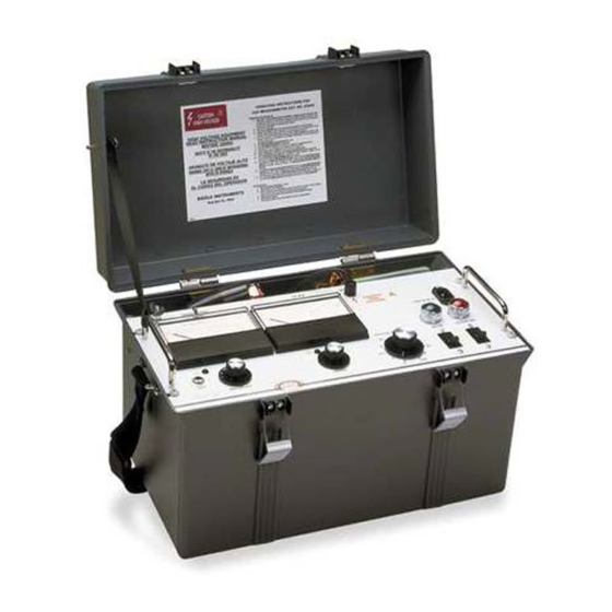
- Page 5 List of Figures Figure a: The Megger Catalog No. 220015 DC Dielectric Test Set..2 Figure 1: Schematic Diagram of Catalog No. 220015......19 Figure 2: Schematic Diagram of Catalog No. 220015-50....... 20 Figure 3: Schematic Diagram of Catalog No. 220015-42....... 21 Figure 4: Schematic Diagram of Catalog No.
- Page 6 List of Tables Table 1: Minimum Air Clearances..............29 Table 2: Measurements of Resistance............50 Table 3: Trouble Location................68 AVTM22-15Ja Rev. A May 2005...
-
Page 7: Introduction
INTRODUCTION This instruction manual is intended as a guide to the operation and maintenance of the portable Dielectric Test Set, Megger Catalog No. 220015 series. References in this manual to optional functions and equipment may be disregarded when such information does not apply to the Test Set in use. -
Page 8: Figure A: The Megger Catalog No. 220015 Dc Dielectric Test Set
Figure a: The Megger Catalog No. 220015 DC Dielectric Test Set AVTM22-15Ja Rev. A May 2005... -
Page 9: Safety Precautions
SAFETY PRECAUTIONS SAFETY IS THE RESPONSIBILITY OF THE USER LA SEGURIDAD ES LA RESPONSABILIDAD DEL OPERADOR The Test Set and the equipment to which it is connected are a source of high-voltage electrical energy. All persons performing or assisting in the tests must use all practical safety precautions to prevent contact with energized parts of the test equipment and associated circuits. - Page 10 Megger considers this an excellent safety practice. Megger strongly recommends the general safety practices contained in IEEE Std. 510 "IEEE Recommended Practices for Safety in High-Voltage and High-Power Testing"...
- Page 11 SAFETY PRECAUTIONS WARNING! Do not use the Cat. No. 220015 Series Test Set for any purpose not described in this Instruction Manual, and do not use accessory items (cables, grounding sticks, etc.) for any purpose except with the specified equipment.
- Page 12 AVTM22-15Ja Rev. A May 2005...
-
Page 13: Receiving Instructions
Examine the instrument for damage received in transit. If any damage is discovered, file a claim with the carrier at once and notify Megger or its nearest authorized sales representative, giving a detailed description of the damage observed. This instrument has been thoroughly tested and inspected to meet rigid inspection specifications before being shipped. - Page 14 AVTM22-15Ja Rev. A May 2005...
-
Page 15: Specifications
SPECIFICATIONS POWER SUPPLY: Catalog No. 220015 Voltage (rms): 105 -130 Volts Recommended Source: NEC 15 Ampere, 120 Volts, single-phase branch circuit (3 wire: line, neutral and ground). Current (rms): 1.5 Amps, maximum continuous. Frequency: 60 Hz, full rating 50 Hz, reduced rating Basis of Rated 120-Volt, 60 Hz supply performance:... - Page 16 OUTPUT TEST 0-15 kV dc, negative with respect VOLTAGE: to ground. OUTPUT CURRENT: Standard or with stabilizer 2 mA continuous, out (-50 option) at 60 Hz: 5 mA for 12 minutes. at 50 Hz: 1.67 mA continuous, 4.17 mA for 12 minutes At 15 kV, 50 µA continuous.
- Page 17 SPECIFICATIONS CONTROLS: Power OFF-ON switch (Circuit Breaker) with green lamp indicator. High-voltage OFF-ON switch (Circuit Breaker) with red lamp indicator. Voltage control with Zero-Start interlock, 0-100 reference dial. Stabilizer selector switch: IN-OUT. Voltmeter Range Switch: 7.5-15 kV. Ammeter multiplier switch, 4-position: x1, x10, x100, x1K CABLES and CONNECTORS Power Supply Cord: 7½...
- Page 18 PHYSICAL: Case: High-impact structural foam, polycarbonate plastic with metal control panel and removable hinged lid. Overall Depth Height Size: Width 20 ½ 13 inches 30.5 33 cm Weight: Catalog No. 220015: 35 ¼ lbs. (16 kg) Catalog No. 220015-47: 39 ½ lbs. (18 kg) Instruction Card: Permanently attached inside lid.
- Page 19 SPECIFICATIONS SAFETY FEATURES: "Zero start" interlock: Voltage Control must be at zero to enable the output voltage circuit to be energized (started). Grounded metal control panel. Separate visible panel ground cable. Permanently attached shielded output cable. Separate switches for control power and high-voltage output.
- Page 20 AVTM22-15Ja Rev. A May 2005...
-
Page 21: Description
DESCRIPTION GENERAL This portable Dielectric Test Set measures the electrical quantities of applied voltage and resultant current in the apparatus to which it is connected. Designed for field or shop use, the complete Test Set (including all leads) is housed in a durable, impact-resistant plastic case, with removable lid and carrying strap. - Page 22 connected to the shield of the output cable with a terminal at the outboard end but is isolated from ground. NOTE: The output cable shield should not be grounded. Grounding this shield will short-circuit the current meter; the meter, therefore, will not register a current measurement.
-
Page 23: Power Supply Option
DESCRIPTION advanced off its zero position. Raising the voltage control now applies a controlled voltage to the primary of T101 through the trip coil of circuit breaker switch CB2. Line voltage transients may cause the ammeter pointer to swing widely, interfering with measurement. A stabilizing (meter damping) switch S102 and a capacitor C104 are provided so that by placing the switch in the IN position (closed), the capacitor will increase the meter damping and... -
Page 24: Overcurrent And Overvoltage Trip
Optional supply voltages may be selected by wiring the transformer assembly in accordance with the table shown in Figure 1. OVERCURRENT AND OVERVOLTAGE TRIP (See Fig. 3, 4 or 5 Schematics) The basic circuitry and general operation of all sets, including those provided with optional features, is as previously described. -
Page 25: Figure 1: Schematic Diagram Of Catalog No. 220015
DESCRIPTION Figure 1: Schematic Diagram of Catalog No. 220015 AVTM21-415Ja Rev. A May 2005... -
Page 26: Figure 2: Schematic Diagram Of Catalog No. 220015-50
Figure 2: Schematic Diagram of Catalog No. 220015-50 AVTM22-15Ja Rev. A May 2005... -
Page 27: Figure 3: Schematic Diagram Of Catalog No. 220015-42
DESCRIPTION Figure 3: Schematic Diagram of Catalog No. 220015-42 AVTM21-415Ja Rev. A May 2005... -
Page 28: Figure 4: Schematic Diagram Of Catalog No. 220015-43
Figure 4: Schematic Diagram of Catalog No. 220015-43 AVTM22-15Ja Rev. A May 2005... -
Page 29: Figure 5: Schematic Diagram Of Catalog No. 220015-101
DESCRIPTION Figure 5: Schematic Diagram of Catalog No. 220015-101 AVTM21-415Ja Rev. A May 2005... - Page 30 AVTM22-15Ja Rev. A May 2005...
-
Page 31: Control And Connector Identification
CONTROL and CONNECTOR IDENTIFICATION 1 Guard Terminal 6. Instruction Card 2. Output Cable 7. Carrying Strap 3. High Voltage Terminal 8. Removable Case Cover 4. Ground Cable 26. Location of -47 Option Step-Down Transformer 5. Power Cord 27. Lead Storage Figure 6A: Overall View of Catalog No. -
Page 32: Figure 6B: Panel View Of Catalog No. 220015
Output Cable 15. 7.5 kV Voltmeter Calibrator Power Cord 16. Kilovoltmeter Range Selector External Instrument Jack 17. 15 kV Voltmeter Calibrator 10. Ammeter Calibrator 18. Voltage Control 11. Ammeter Multiplier Selector 19. AC "ON" Green Lamp 12. Ammeter 20. Input Power Switch 13. -
Page 33: Setting Up
SETTING UP Test set controls and terminals are identified in Section 6. The following steps are listed as a general guide for setting up the Dielectric Test Set. Suggested setup arrangements are shown in Figures 7 through 11. PREPARATION Before setting up the test equipment, read Section 2, SAFETY. Working with due regard to safety, identify the terminals of the apparatus to be tested. -
Page 34: Connections Procedure
NOTE: For operator safety, the output cable should be fully extended to provide maximum distance between the operator and the high-voltage terminal. 3. A reliable ground connection must be within 12 feet of the Test Set. 4. If an electrical service outlet is not within range of the input cable, a UL-approved extension cord rated for 15 amperes (minimum) and not longer than 50 feet may be used. -
Page 35: Clearances
SETTING UP 5. With the Test Set switch OFF, connect the power cord to the service outlet. CLEARANCES Be sure adequate clearances are maintained between energized conductors and ground to prevent arc-over. Such accidental arc-over may create a safety hazard or damage the equipment being tested. -
Page 36: Power Supply Option, Catalog No. 220015-47
POWER SUPPLY OPTION, Catalog No. 220015-47 Test Sets with Optional Features Test sets equipped with either the overcurrent or overvoltage options, or both, are set up as previously described; however, before conducting a test, the desired limits of voltage and/or current should be set in accordance with the instructions given in Section 8. -
Page 37: Figure 7: Testing In A Substation
SETTING UP Figure 7: Testing in a Substation. AVTM21-415Ja Rev. A May 2005... -
Page 38: Figure 8: Testing Parking Lot Lighting; The Test Set Shown Is Operating From An Inverter
Figure 8: Testing Parking Lot Lighting; the Test Set Shown is Operating from an Inverter AVTM22-15Ja Rev. A May 2005... -
Page 39: Figure 9: Testing Transformer Terminals
SETTING UP Figure 9: Testing Transformer Terminals. AVTM21-415Ja Rev. A May 2005... -
Page 40: Figure 10: Dc Motor Test Setup
Figure 10: DC Motor test setup. Figure 11: Generator test setup. AVTM22-15Ja Rev. A May 2005... -
Page 41: Operation
OPERATION When the Test Set and apparatus to be tested are set up as indicated in Section 7, the equipment can be energized and the required tests run by following the steps given below. NOTE: Before operating the Dielectric Test Set, read Section 2 of this manual and ensure that all appropriate safety precautions are observed. -
Page 42: Breakdown Of Test Item
8. Turn voltage control clockwise to increase output voltage as required for test being conducted. 9. Note voltage, resistance and time as required by the test procedure being followed. Make settings and take readings as described in steps below. 10. If indicated current fluctuates during the reading, the stabilizing switch may be set to the "IN"... -
Page 43: Normal Shutdown Procedure
OPERATION NORMAL SHUTDOWN PROCEDURE When the test has been completed, follow this shutdown procedure: 1. Set the voltage control to zero. 2. Open the AC "ON" switch or the OUTPUT "ON" switch or both. 3. When the voltmeter indicates that voltage has decreased to a value of less than half the voltage used during the test, use an insulated grounding stick to apply a direct short circuit to all ungrounded terminals of the apparatus being... - Page 44 AVTM22-15Ja Rev. A May 2005...
-
Page 45: Operation Notes
Test Set. Megger recommends that when using the Cat. No. 220015-47, the service supplying the Test Set be protected by a fuse of not less than 1¼... -
Page 46: Stabilizing Switch
STABILIZING SWITCH This switch acts on the current meter circuit only. During the measurement of leakage current on apparatus having significant capacitance, small line voltage transients can result in large transient swings of the current meter. This effect will be most noticeable when using the 5 µA range and will require that the operator judge the indicated current value by visually and mentally averaging the value. -
Page 47: Use Of Guard
OPERATION NOTES USE OF GUARD (see also Section 10) Occasionally when measuring apparatus, the leakage resistance of interest is masked by a parallel path. Such a situation is often encountered when measuring the leakage current of a cable. In the practical situation, the value of the resistance along the leakage path from the conductor over the surface of the pothead may be less than that within the major length of the cable. -
Page 48: Use Of Regulation Curve (-50 Option)
To predetermine the voltage control setting, refer to the regulation curve given in Figure 12. The accuracy of the voltage setting will normally be on the order of 5 to 10%, depending on the line voltage and the nature of the apparatus being tested (see next paragraph). - Page 49 OPERATION NOTES above this level a spark forms at the failure, the voltage collapses, and the current soars. This will usually trip out the Test Set; but if the voltage control is set just beyond the voltage that causes arc-over, it is possible that the arc-over will repeat several times before trip out.
-
Page 50: External Current Meter
EXTERNAL CURRENT METER To read or record the test current, connect a suitable instrument to a two-wire phone plug that mates with EXT. INST jack J1. The tip of the plug will be positive, the ring negative. The external meter impedance must not exceed 10,000 ohms. -
Page 51: Figure 13: Typical Guard Connection To Cable Pothead
OPERATION NOTES Figure 13: Typical Guard Connection to Cable Pothead Figure 14: Guard Connection for a Typical Cable Test AVTM21-415Ja Rev. A May 2005... -
Page 52: Figure 15: Typical Guard Connection For An Oil Circuit Breaker
Figure 15: Typical Guard Connection for an Oil Circuit Breaker Figure 16: Typical Guard Connection for Transformer Test AVTM22-15Ja Rev. A May 2005... -
Page 53: Application Notes
APPLICATION NOTES THEORY OF INSULATION TESTING Any device that uses electrical energy can ordinarily be considered as consisting of elements that may be classified in two separate categories, namely, those parts of the apparatus that conduct the electrical energy and those parts that are not intended to conduct. -
Page 54: Applying The Test Set To Grounded Test Object
Guide for Testing Insulation Resistance of Rotating Machinery, IEEE Standard 43. Guide for Insulation Maintenance for Large Alternating Current Rotating Machinery. IEEE Standard 46. Guide for Making Dielectric Measurements in the Field. IEEE Standard 62. Guide for Insulation Testing of Large AC Rotating Machinery with High Direct Voltage. -
Page 55: Three-Terminal Vs. Two-Terminal Tests
APPLICATION NOTES THREE-TERMINAL vs. TWO-TERMINAL TESTS There are certain important practical situations where a two- terminal measurement does not convey the desired information. In Section 9 the guard was recommended when testing cable. In practical application, this arrangement can resolve the problem that the dirty surface path over the pothead may conduct more current to ground than actually passes through the bulk of the cable itself. -
Page 56: Figure 17: Two-Winding Transformer In Three-Terminal Form
In Figure 17 this case is shown schematically, with the three insulation paths of interest shown as resistances. Figure 17: Two-Winding Transformer in Three-Terminal Form. It is convenient to treat each insulation measurement as a resistance reading; the equivalent resistance for each measurement is equal to the test voltage divided by the measured current. -
Page 57: Generalized Combined 2 And 3 Terminal Measurement
APPLICATION NOTES NOTE: There are alternate forms possible for the desired equation and measurement table. GENERALIZED COMBINED 2 and 3 TERMINAL MEASUREMENT The schematic of Figure 17 is equivalent to three delta- connected resistors with one junction grounded. Many problems can be reduced to this form and then evaluated by the technique given above. - Page 58 AVTM22-15Ja Rev. A May 2005...
-
Page 59: Routine Maintenance
ROUTINE MAINTENANCE INTRODUCTION Field service subjects high-voltage test equipment to a difficult environment but equipment wear can be minimized by periodic inspection and cleaning. Such inspections and cleaning will also ensure reliable on-the-job operation. The frequency of routine inspection and cleaning will depend on the field conditions encountered. - Page 60 2. Wipe the outside of the case with the damp cloth; then dry with a clean dry cloth. 3. Open the lid; fully extend and visually inspect all cables. If necessary, wipe each cable with the damp cloth; then dry. Wipe out the lead compartment.
- Page 61 ROUTINE MAINTENANCE 7. Completion of Inspection A. Wipe the circuit card with a clean dry cloth to remove accumulated dust. Wipe the interior of the case. Visually inspect the interior connections and components. B. Re-install the guard screens. Make sure that the rear screen fully clears the panel-mounted resistor R1 and that the front screen fully clears the Zener diodes CR1 and CR2.
- Page 62 AVTM22-15Ja Rev. A May 2005...
-
Page 63: Troubleshooting And Repair
TROUBLESHOOTING and REPAIR GENERAL Megger maintains a complete repair service and recommends that its customers take advantage of this service in the event of equipment malfunction. The instrument will be cleaned and excessively worn or damaged parts replaced. Following repair, the instrument will perform functionally like a new instrument, but the appearance will be substantially as returned. -
Page 64: Case Repairs
component. The schematic diagram in Section 5 and the interior view of the Test Set given in Figure 18 will be helpful in locating components. When ordering parts, always include the Test Set serial number. The location of the serial number is shown in Figure 18. -
Page 65: Changing Line Voltage Tap (-47 Models Only)
TROUBLESHOOTING & REPAIR 3. Carefully unsolder the output cable center conductor from the shield eyelet. 4. Mark all leads on the panel terminal strip and disconnect them. 5. Locate the four nuts that secure the chassis to the panel; with the set upright on the chassis remove the nuts, lock washers and flat washers. -
Page 66: Replacement Of Meters Or Meter Amplifier Board
REPLACEMENT OF METERS OR METER AMPLIFIER BOARD 1. Place the panel on a clean cloth with the meters face down. 2. Remove the leads and note the terminals to which they should be reconnected. 3. Remove amplifier board if necessary (current meter only). 4. -
Page 67: Replacement Of Stabilizing Switch S1
TROUBLESHOOTING & REPAIR 3. Replace the switch assembly and tighten the switch bushing nut. 4. Replace the knob, align it with the panel index, then tighten the knob on the shaft. 5. Resolder the leads to the printed circuit card. REPLACEMENT OF STABILIZING SWITCH S1 1. -
Page 68: Replacement Of Voltage Control Autotransformer T1
REPLACEMENT OF VOLTAGE CONTROL AUTOTRANSFORMER T1 1. Disconnect all leads, noting the appropriate reconnection terminal for each. 2. Remove the voltage control knob. 3. Remove the bushing nut. 4. Pull the transformer free of the assembly. 5. Replace the transformer through the panel. 6. -
Page 69: Replacement Of Circuit Card U2
7.5 kV and 15 kV with an accuracy of +1% or better. On either range this standard instrument should draw less than 0.5 mA. The Megger AC/DC 20 kV Kilovoltmeter, Cat. No. 513020 is recommended. 1. Connect the Test Set as shown in Figure 19. -
Page 70: Calibration Of Current Meter
5. Using a fine blade screwdriver, adjust the 7.5 kV potentiometer through the 7.5 kV CAL hole until it agrees with the standard. 6. Check at 7.5 kV full scale, then repeat for the 15 kV range using the 15 kV CAL adjustment and an output of 10 kV. Check at 15 kV full scale. - Page 71 TROUBLESHOOTING & REPAIR 4. Increase the output voltage until standard current meter indicates 5 µA (at almost 500 volts). 5. The Test Set meter should read 5 microamperes. If the required accuracy is not met, the meter with amplifier U4 or its protective network may require repair.
-
Page 72: Adjustment Of R1 In Stabilization Network (-50 Option)
ADJUSTMENT OF R1 IN STABILIZATION NETWORK (-50 OPTION) The objective of this adjustment is to dissipate no more than 48 watts in the stabilizing Zener diodes CR1 and CR2 at maximum line voltage and minimum burden (output current) on the Test Set. CATALOG NO. -
Page 73: Catalog No. 220015-47,-50
TROUBLESHOOTING & REPAIR 10. Increase the supply voltage to 130 volts +2%. 11. The current should be 1.09 times the reading of step 8, plus 0.3 Amperes. 12. If the value observed is greater than calculated in step K, shut down and move the R1 tap so as to increase the included resistance. -
Page 74: Trouble Location Chart
TROUBLE LOCATION CHART TABLE 3: TROUBLE LOCATION MALFUNCTION POSSIBLE CAUSE AC "ON" lamp does not light. De-energized service outlet. Defective service outlet. Defective power cord. Defective lamp. Defective CB1. AC "ON" lamp abnormally Supply voltage too high. bright. AC "ON" switch trips on Internal wiring short circuit. - Page 75 TROUBLESHOOTING & REPAIR MALFUNCTION POSSIBLE CAUSE No ammeter reading. Guard connected to ground. Range switch set too low. Defective M102. Defective U1. Defective J101. W101 not connected to apparatus under test. No ground on apparatus under test. Ammeter reading erratic. Supply voltage unstable.
-
Page 76: Figure 18: Interior Views
Figure 18: Interior Views. AVTM22-15Ja Rev. A May 2005... -
Page 77: Figure 19: Connections For Calibration Of Voltmeter
TROUBLESHOOTING & REPAIR Figure 19: Connections for Calibration of Voltmeter. Figure 20: Connections for Calibration of the Current Meter AVTM21-415Ja Rev. A May 2005... - Page 78 AVTM22-15Ja Rev. A May 2005...
-
Page 79: Performance Check
PERFORMANCE CHECK The procedure given below can be used to check equipment performance in the shop after routine maintenance as described in Section 11, or after making repairs as indicated in Section 12. The procedure may be used in the field prior to conducting tests to confirm that the equipment is operating properly and thereby ensure valid test results. - Page 80 4. With voltage control set for 15 kV output, set stabilizer to "IN". Voltage should drop to about 13.5 kV (-50 Option only). 5. Follow the shutdown procedure given in Section 8. 6. Connect the high-voltage output to ground. 7. Set the voltmeter range to 7.5 kV and the ammeter range to X1K, stabilizer "OUT".
-
Page 81: Parts List
PARTS LIST SYMBOL DESCRIPTION PART NO. Complete case and lid 25743-1 Case feet 5599-1 Carrying strap and bails 6580-2 Input cable (power cord) 17032 W101 Output cable 10586 W102 Ground cable 4702 AC "ON" switch 4709 HV "ON" switch 4710 DS1/DS2 Lamps only 6S6-125 1723... - Page 82 SYMBOL DESCRIPTION PART NO. M101 Voltmeter 25293 S101 Voltmeter range selector pc 22521 R104 Output current limit resistor 4500-101 Ammeter protective-range selector pc 4986 M102 Ammeter 25292 J101 External instr. jack 4733-2 Voltage control knob 4690-1 Ammeter range knob 9998-81 Voltmeter range knob 9998-5 Meter amplifier board...
-
Page 83: Warranty And Repairs
WARRANTY and REPAIRS WARRANTY All products supplied by Megger are warranted against all defects in material and workmanship for a period of one year following shipment. Our liability is specifically limited to replacing or repairing, at our option, defective equipment. - Page 84 AVTM22-15Ja Rev. A May 2005...
Need help?
Do you have a question about the 220015 Series and is the answer not in the manual?
Questions and answers