Table of Contents
Advertisement
Quick Links
Advertisement
Table of Contents

Related Manuals for Megger MFT-X1


Summary of Contents for Megger MFT-X1
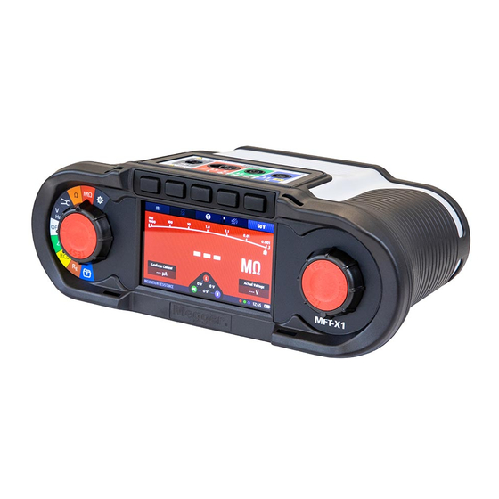
- Page 1 MFT-X1 Multifunction tester User Guide...
- Page 2 T +44 (0)1304 502101 F +44 (0)1304 207342 www.megger.com Megger Ltd reserves the right to alter the specification of its products from time to time without notice. Although every effort is made to ensure the accuracy of the information contained within this document it is not warranted or represented by Megger Ltd.
- Page 3 Directive 2014/53/EU. Other equipment manufactured by Megger Instruments Limited described in this user guide is in compliance with Directives 2014/30/EU and 2014/35/EU where they apply. The full text of Megger Instruments EU declarations of conformity are available at the following internet address: megger.com/eu-dofc www.megger.com...
-
Page 4: Table Of Contents
4.3.6 Analogue arc............................22 5. Operation ............................23 Switching on and off ..........................23 5.1.1 Auto power off (sleep function)........................ 24 Test inhibit – general inhibits ........................24 6. Dead circuit tests ..........................25 General ............................... 25 Protection against accidental damage ..................... 25 MFT-X1 www.megger.com... - Page 5 Auto-start (hands-free) option ....................... 40 10.4 Protective earth and touch voltage warnings ..................41 10.4.1 Protective earth warning (PE) operation ....................41 10.4.2 Inhibit protective earth confirmation (PE warning) .................. 42 10.5 Touch voltage (fault voltage) ......................... 42 www.megger.com MFT-X1...
- Page 6 RCD testing at a single current ....................... 55 13.7 Ramp testing RCDs ..........................57 13.8 Touch-voltage test ........................... 58 13.9 VAR (Variable RCD) ..........................59 13.9.1 Using the VAR option ..........................59 13.9.2 Setting the VAR option ........................... 60 MFT-X1 www.megger.com...
- Page 7 15.5.2 Backlight timer ............................79 15.5.3 Contrast mode ............................79 15.5.4 Setting the date ............................. 79 15.5.5 Setting the time ............................. 80 15.5.6 Key press beep ............................80 15.5.7 Results beep ............................80 15.5.8 Sleep timer ............................. 81 15.5.9 Language ............................... 81 www.megger.com MFT-X1...
- Page 8 Connecting to the MFT-X1 from CertSuite™ ..................90 16.5 Failure to connect ............................ 91 16.6 Sleep mode and power cycling the MFT-X1 ................... 91 16.7 Sending test results to CertSuite™ ......................92 16.8 Re-sending test results to CertSuite™ ....................92 16.9...
- Page 9 20. Accessories and equipment ......................107 20.1 Included accessories..........................107 20.2 Optional accessories ..........................107 21. Calibration, Repair and Warranty ....................108 21.1 Return procedure ............................ 108 22. Decommissioning ..........................109 22.1 WEEE Directive ............................109 22.2 Battery disposal ............................109 www.megger.com MFT-X1...
-
Page 10: Introduction
Please read the guide carefully before you start using your MFT-X1. Product description The MFT-X1 is a multifunction tester designed primarily for testing electrical installations to meet the requirements of international regulations and standards. It has been designed with safety, versatility, ease of use and reliability in mind and it has an entirely new user interface that simplifies and speeds up testing as well as greatly reducing the risk of errors. -
Page 11: Features
Company web site Occasionally an information bulletin may be issued via the Megger web site. This may be new accessories, new usage instructions or a software update. Please occasionally check on the Megger web site for anything applicable to your Megger instruments. -
Page 12: Safety Warnings
„ In this case, the circuit must be discharged by other means. „ Do not touch circuit connections and exposed metalwork of an installation or equipment under test. Under fault conditions the system earth could become hazardous live. MFT-X1 www.megger.com... -
Page 13: Earth Test Warnings
MUST be followed. „ Only Megger approved test leads must be used with this product. All test leads, probes and crocodile clips must be in good order, clean, and with no broken or cracked insulation. -
Page 14: Li-Ion Battery Module Warnings
The category ratings are explained below. When used with approved Megger test- leads, MFT-X1 instrument has a CAT IV 300 V and CAT III 600 V rating, but with some accessories, this rating may be reduced. -
Page 15: Safety, Hazard And Warning Symbols On The Instrument
symbol on the top left of the terminal panel label: Unmated terminals can be energized from within the instrument and from external connection of other terminals. The current clamp must be the type indicated as “MCC1010” to ensure safe connection to the instrument. www.megger.com MFT-X1... -
Page 16: Getting Started
Starts when TEST button is pressed and released Stops automatically on completion of test Loop Impedance: Starts when TEST button is pressed and released Stops automatically on completion of test RCD: Starts when TEST button is pressed and released Stops automatically on completion of test MFT-X1 www.megger.com... -
Page 17: Instrument Controls
Instrument Controls 4. Instrument Controls Instrument layout The front panel of your MFT-X1 multifunction tester has four main areas: Item Description Item Description Hot keys Secondary rotary selector knob Primary rotary selector knob Display Item Description Item Description Hanging strap/neck strap attachment... -
Page 18: Instrument Display
Instrument Controls Instrument display The MFT-X1 display is a 480 x 272 colour TFT screen, with a toughened and bonded glass screen. The display is divided into three areas: Item Description Item Description Hot key bar – Shows key functions Information bar –... -
Page 19: High Contrast Mode
Refer to 15.5.3 Contrast mode on page 79. Instrument controls The MFT-X1 has two rotary selector knobs. These allow the user to select the main measurement functions and the Hot key minor measurement functions: Left rotary selector – Main measurement modes „... -
Page 20: Information Bar
Required test-lead connections NOTE : Test results are time stamped with the time and date. The time is displayed permanently in the INFO bar. The format can be changed. Refer to 15.5.4 Setting the date on page 79. MFT-X1 www.megger.com... -
Page 21: Test Lead Connection Guide
2. 2 wire testing is OK for AC and A type RCDs but RDC and type B devices require three wire connection. 3. Connecting the neutral provides reverse polarity detection (also mandatory on DC RCDs and RDC). 4. Connection for MCC1010 in current mode. www.megger.com MFT-X1... -
Page 22: Voltage Widget
The ‘pointer’ on this arc moves across the arc to give an indication of the measured value. The behavior of the pointer can provide extra information about the condition of the circuit. Refer to 8. Insulation testing on page 32. MFT-X1 www.megger.com... -
Page 23: Operation
Fig 8: Start up screen To turn the MFT-X1 off, return the left-hand rotary knob to the ‘off’ position on the display. The display screen goes dark, confirming that the instrument is off and no longer using power from the battery. -
Page 24: Auto Power Off (Sleep Function)
5.1.1 Auto power off (sleep function) If you leave your MFT-X1 switched on but do not use it, the display will dim after 20 seconds, and after 5 minutes (default setting) it will automatically turn itself off to avoid wasting battery power. When this happens, you can turn it back on again by pressing any buttons. -
Page 25: Dead Circuit Tests
Protection against accidental damage MFT-X1 instruments are protected against the damage that might otherwise occur if you select a dead circuit test and connect the instrument to live circuit. The protection is effective even if you’ve started a live circuit test and locked it on. -
Page 26: Continuity Testing And Resistance Measurement
General information 7.1.1 Basic functions Instruments in the MFT-X1 range can check continuity and measure resistance from 0.01 Ω up to 999 kΩ, which means that you no longer need to use a separate meter to make resistance measurements. A buzzer function is also provided which can speed up routine testing but, when this function is used, resistance measurements are limited to a maximum of 2.00 kΩ... -
Page 27: Test Inhibit
This mode cannot be overridden and inhibits all testing until the source of the voltage is removed. 7.1.3 Hot keys for continuity checking and resistance measurement When the MFT-X1 is being used to check continuity or measure resistance, the functions of the Hot keys are: Hot key 1... -
Page 28: Continuity Testing
7. For help on connection of test leads to the circuit, press HELP on Hot key 2 8. To save the result or send to a mobile device, Refer to 16. Download results to a remote device on page 89. MFT-X1 www.megger.com... -
Page 29: Test Lead Null
Fig 15: Continuity null NOTE : It is a good idea to occasionally check the null value is correct, as test leads may not always give a consistent lead resistance if they are wearing out and need replacement. www.megger.com MFT-X1... -
Page 30: To Check The Lead Null Value
Ensure there is a good connection during the nulling process. Possibly use a piece of copper pipe or bar to join the leads. Repeat the test-lead process as described above. Check the test-leads for signs of damage. „ Use a copper bar or piece of pipe to join the leads. „ MFT-X1 www.megger.com... -
Page 31: Buzzer Mode Up To 2 Kω (1 Kω On Analogue Scale)
(limit alaram) on page 83. ƒ The preset value is displayed in the bottom of the display as shown in the example right. Here the buzzer limit has been set to 1 Ω. Fig 17: Continuity buzzer and threshold www.megger.com MFT-X1... -
Page 32: Insulation Testing
The MFT-X1 can test insulation at 50 V, 100 V, 250 V, 500 V and 1,000 V. It can also test at a wide range of intermediate values using the VAR option. Most common values are: „... -
Page 33: Hot Keys For Insulation Tests
If you have an insulation test selected and you connect the test-leads to a circuit carrying a voltage greater than „ the live voltage limit, a lightning warning symbol flashes in the display, an audible warning sounds and the voltage widget appears, as shown below: www.megger.com MFT-X1... -
Page 34: Insulation Testing
4. Press Hot key 5 until the test voltage you want is shown below it. 4.1. Alternatively, press Hot key 5 once and use the right-hand rotary knob to select the test voltage. 5. Connect your test-leads to the circuit or asset you want to test. MFT-X1 www.megger.com... -
Page 35: Insulation Test With Test Lock
4. Press Hot key 5 until the test voltage you want is shown below it. 4.1. Alternatively, press Hot key 5 once and use the right-hand rotary knob to select the test voltage. 5. Connect your test-leads to the circuit or asset you want to test. www.megger.com MFT-X1... - Page 36 WARNING : When the insulation test is locked on, the instrument does not discharge the circuit or asset at the end of a test. The circuit and test-leads remain live and hazardous. Ensure that you discharge the circuit safely before touching any connections. MFT-X1 www.megger.com...
-
Page 37: Earth Resistance Measurement
You must also ensure that you correctly reconnect the earth electrode after completing the test. Fig 23: Earth resistance measurement General The MFT-X1 can be used to measure the resistance of earth electrodes using the following methods: ƒ two-pole The default test voltage is 50 V, but this can be changed to 25 V by pressing Hot key 1 at the beginning of the test for making measurements in, for example, areas where local conditions require a lower test voltage, such as in the presence of livestock. -
Page 38: Two-Pole Earth Resistance Measurements
Not used. Before starting a test, press for help on earth resistance measurement. Help/Save When the test is complete, press to transfer the results to a connected Bluetooth device. ® Not used Test type Currently only allows 2P testing. MFT-X1 www.megger.com... -
Page 39: Two-Pole (2P) Earth Resistance Measurements
6. Plug a test lead into the yellow socket and connect it to the test stake. 7. Press and release the test button. 8. At the end of the test, the main area of the display shows the earth resistance. 9. Reconnect the earth electrode. www.megger.com MFT-X1... -
Page 40: Live Circuit Tests
10.3 Auto-start (hands-free) option The MFT-X1 has an auto-start option for Loop impedance and RCD testing. This option is turned off by default but if you turn it on in SETUP. When enabled in settings the (hands-free) auto-start function must be primed by pressing a TEST button prior to connection to the circuit. -
Page 41: Protective Earth And Touch Voltage Warnings
When making a measurement on live circuits the red pad on either of the test buttons should be touched for at least 1 second to allow the PE warning detection to operate. NOTE : Do not press the test button, just touch it. This is adequate for the detection circuit to identify a fault without instigating a measurement. www.megger.com MFT-X1... -
Page 42: Inhibit Protective Earth Confirmation (Pe Warning)
25 V in set up Refer to 15.8.2 Maximum touch voltage on page 85. You can also carry out a touch-voltage test on its own in the RCD test options. Refer to 10.5 Touch voltage (fault voltage) on page 42. MFT-X1 www.megger.com... -
Page 43: Voltage Measurement
Fig 30: Voltage single phase WARNING : When using the MFT-X1 you should remember that if you have selected AC mode and the reading is low or zero, the circuit could still have a potentially dangerous DC voltage present. Conversely, if you have selected DC mode and the reading is low or zero, the circuit could have a potentially dangerous AC voltage present. -
Page 44: Hot Keys For Voltage Measurements
Alternatively, you can select the mode by pressing Hot key 5 once and using the right-hand rotary knob. „ To get help, press Hot key 2 at any time. „ The voltage widget is inhibited during voltage tests as the main bar of the display shows the voltages more accurately. MFT-X1 www.megger.com... -
Page 45: Single-Phase Measurements
The test is running continuously and is constantly displaying the voltages on the test terminals. 4. For two-wire tests, the instrument displays a single voltage. 4.1. For three-wire tests, the live-to-PE, live-to-neutral and neutral-to-PE voltages are displayed simultaneously. www.megger.com MFT-X1... -
Page 46: Three-Phase Measurements
If the instrument is set to DC mode and phase rotation is detected, it automatically switches to TRMS mode and the display area below Hot key 5 flashes five times to alert the user. Fig 35: Hot key 3 MFT-X1 www.megger.com... -
Page 47: Millivolt Measurements
Press Hot key 3 at any time to send the results shown in the main area of the display to a connected Bluetooth ® device such as a tablet or smartphone Fig 36: Hot key 3 For information about connecting mobile devices with the MFT-X1, Refer to 16. Download results to a „ remote device on page 89. www.megger.com... -
Page 48: Current Measurement
WARNING : Current measurements are live circuit tests and all precautions for live working must be followed. Fig 37: Current measurement 12.1 General When used with an optional MCC1010 current clamp, the MFT-X1 can measure AC and TRMS currents. 12.2 Hot keys for current measurements Hot key 1 Hot key 2... -
Page 49: All Current Measurements
1. Turn the left-hand rotary knob to the position marked CURRENT. ƒ The display illuminates and has a black background. 2. Using a Megger MCC1010 clamp, plug it into the grey 3 pin socket. NOTE : This is a polarized connection. Do not force the plug into the socket. -
Page 50: Residual Current Device (Rcd) Testing
The MFT-X1 has a limit of 1000 mA for any test selected. With some higher current RCDs and especially type A or type B RCD, the range of tests that you can carry out is restricted. For example, the MFT-X1 cannot perform 5 x I tests on RCDs with a 300 mA rating or higher, as this would require a test current of 5 x I or 5 x 300 mA = 1500 mA, exceeding the 1000 mA limit. -
Page 51: About The Rcd Tests
For this test, the instrument uses a current equal to twice the rating (2 x I) of the RCD under test. The RCD should trip within 150 ms. When the RCD trips the test stops and the instrument shows the actual trip time. If the RCD fails to trip, the test stops after 150 ms, and the display shows >150 ms. www.megger.com MFT-X1... -
Page 52: The 5 X I Test
230 V supplies and 376 V AC to 550 V AC for nominal 400 V AC supplies), or if the supply frequency is outside the acceptable frequency range (45 Hz to 65 Hz for nominal 50 Hz supplies). MFT-X1 www.megger.com... -
Page 53: Hot Keys For Rcd Tests
While the instrument is carrying out a test, all the Hot keys are disabled. „ To test RCDs with a current rating that does not match any of the presets that the instrument offers, you can use the VAR option, Refer to 13.9 VAR (Variable RCD) on page 59. www.megger.com MFT-X1... -
Page 54: Automatic Rcd Testing
AUTO sequence table of results. 8. Once the tripping test commence, the RCD will need to be reset for the sequence to continue. NOTE : The tests will automatically start when the RCD is reset. MFT-X1 www.megger.com... -
Page 55: Customising The Auto Test Sequence
B or EV modes use 3 leads testing. Plug your L (red) test-lead into the red socket, your PE (green) test-lead into the green socket and your N (blue) test-lead into the blue socket. Three-wire is necessary for type B RCDs and EV/RDC. www.megger.com MFT-X1... - Page 56 NOTE : Connection can be made at the end of the circuit, in the distribution board or on the RCD. NOTE : Some RCBOs will not trip if tested by connecting directly onto the screw terminals of the RCBO. They should be tested from further down-stream, either in the distribution board or at a local socket. MFT-X1 www.megger.com...
-
Page 57: Ramp Testing Rcds
NOTE : Connection can be made at the end of the circuit, in the distribution board or on the RCD NOTE : Some RCBOs will not trip if tested by connecting directly onto the screw terminals of the RCBO. www.megger.com MFT-X1... -
Page 58: Touch-Voltage Test
RCD you are testing. 5. Repeatedly press Hot key 5 until the touch-voltage test (Touch V) is shown. 5.1. Alternatively, press Hot key 5 once and use the right- hand rotary knob to select the touch-voltage test. MFT-X1 www.megger.com... -
Page 59: Var (Variable Rcd)
The same maximum current limit applies to standard values. That is the maximum current cannot exceed 1000 mA. So, a 250 mA type AC test cannot be run at 5 x I as it will exceed 1000 mA. www.megger.com MFT-X1... -
Page 60: Setting The Var Option
The VAR option is now set. ƒ Pressing a test button will now run the selected test with the VAR value. 8. To change the VAR setting, repeat this procedure, remembering to press Hot key 3 to confirm the new setting. MFT-X1 www.megger.com... -
Page 61: Earth Loop Impedance Testing - Trueloop
14.1 General The MFT-X1 uses the unique Megger TrueLoop™ technology to carry out earth Loop Impedance measurements (which are often called Loop Impedance test or just loop tests) in single and three-phase installations. They can also be used to measure Loop Impedance of all line conductors such as Live to Neutral and Live to Live. -
Page 62: Using The Confidence Meter
– but you will only need to record the highest of the values you measure. On a radial circuit this will be the end of the circuit. To make this easier, the MFT-X1 has a Zmax function which stores and displays the highest out of a series of consecutive measurements (Refer to 14.9 Zmax –... -
Page 63: Loop Test Options
NOTE : There is always a very small risk that an RCD may trip during a test. If this is unacceptable, you may need to consider alternative methods of measuring the Loop Impedance. For further advice, contact the Megger technical support service. www.megger.com... -
Page 64: Hot Key 3 - No Rcd, Rcd Or Ev Rdc Options
Testing the L1-L2 Loop Impedance For use with 2 wire methods only „ L2-L3 Testing the L2-L3 Loop Impedance For use with 2 wire methods only „ L3-L1 Testing the L3-L1 Loop Impedance For use with 2 wire methods only MFT-X1 www.megger.com... -
Page 65: Test Inhibit
Test-lead null To ensure best accuracy in a loop test, the MFT-X1 allows the test-lead resistance to be nulled. This prevents the lead resistance from adding to the Loop Impedance. The MFT-X1 uses the continuity test-lead null to achieve this. -
Page 66: Loop Test Recommendation Table
1. Turn the left-hand rotary knob to the Loop Impedance test position. ƒ The display illuminates with a green background. 2. Plug your L (red) test-lead into the red socket and your PE (green) test-lead into the green socket. MFT-X1 www.megger.com... - Page 67 Refer to 15.8.3 AUTO test start on page 85. 9. When the Confidence Meter™ bar reduces towards the middle as the circuit is analyzed. 10. When the test is complete, the display shows the Loop Impedance, in this case ZL-PE and the prospective earth-fault current, IPEFC. www.megger.com MFT-X1...
-
Page 68: Measuring Loop Impedance (Zs) With Rcd Protection In Circuit
NOTE : If AUTO START is enabled in settings, press the test button BEFORE connecting the test-leads. The test will then start when it detects a live circuit on connection of the leads, Refer to 15.8.3 AUTO test start on page 85. MFT-X1 www.megger.com... -
Page 69: Measuring Ev Charger Loop Impedance
3.1. Alternatively, press Hot key 1 once and use the right- hand rotary knob to select the Zmax function. 4. Repeatedly press Hot key 2 to select RCD. 4.1. Alternatively, press Hot key 2 once and use the right- hand rotary knob to select RCD www.megger.com MFT-X1... - Page 70 If AUTO START is enabled in settings press the test button BEFORE connecting the test-leads. 12. Press and release the test button if AUTO START is not enabled. 13. When the Confidence Meter™ bar reduces towards the middle as the circuit is analyzed. MFT-X1 www.megger.com...
-
Page 71: Zref - Making And Using The Reference Impedance For R1+R2 And Vdrop Calculations
2. Plug your L (red) test-lead into the red socket and your PE (green) test-lead into the green socket. 3. Repeatedly press Hot key 1 to select Zref. 3.1. Alternatively, press Hot key 1 once and use the right- hand rotary knob to select Zref. www.megger.com MFT-X1... - Page 72 10. When the test is complete, the display shows the external reference impedance (Zref). 11. The instrument stores the value of Zref even if you turn the instrument off. 12. To update Zref, repeat the measuring procedure. MFT-X1 www.megger.com...
-
Page 73: R1 + R2 Mode
If AUTO START is enabled in settings press the test button BEFORE connecting the test-leads. 10. The Confidence Meter™ bar reduces towards the middle as the circuit is analyzed. 11. When the test is complete, the display shows the R1+R2 value and the Zref used to calculate it. www.megger.com MFT-X1... -
Page 74: Setting I-Vdrop For Volts Drop Measurements
71.). Remember this is usually the point the supply enters the building, or as close as is safely practicable. NOTE : To measure the volt drop between the point the supply enters the building and the end of a final circuit, measure Zref at the point the phase and neutral enter the building. MFT-X1 www.megger.com... -
Page 75: Setting I-Vdrop
The circuit maximum current (i-vdrop) is now set and will be shown in the lower right of the V-drop display. 7. To change the i-vdrop current, repeat this procedure, remembering to press Hot key 3 to confirm the new setting. www.megger.com MFT-X1... -
Page 76: Making A Volt Drop Measurement
It will also display the Line to Neutral Loop Impedance (ZL-N) or the Phase to Phase impedance (depending on Hot key 5 setting, and the prospective short-circuit current, IPSSC. MFT-X1 www.megger.com... -
Page 77: Instrument Settings Navigation
15. Instrument settings navigation The MFT-X1 provide a wide range of setting options that you can use to configure them to suit your own requirements and the way you work. You set almost all these options using the instrument set up features described in this section. -
Page 78: Entering And Leaving Settings Mode
Contrast mode ƒ Sleep timer ƒ Reset to factory setting Date Language ƒ ƒ Time PE confirmation ƒ ƒ 3. Press Hot key 3 to confirm your selection or to change the status if it is an ON/OFF function. MFT-X1 www.megger.com... -
Page 79: Screen Brightness
9. Rotate the disc to select the month. 10. Use Hot key 5 to select the fourth disc from the left. 11. Rotate the disc to select the year. 12. Press Hot key 3 to confirm and store the date setting. www.megger.com MFT-X1... -
Page 80: Setting The Time
ƒ If this option is on, the instrument beeps when a measurement is complete and the results are ready. 2. Press Hot key 3 to turn the results beep off or on. 3. Your choice is stored automatically. MFT-X1 www.megger.com... -
Page 81: Sleep Timer
If this option is on, the instrument inhibits testing if it detects a voltage between the user and protective earth that is greater than the touch voltage Refer to 10.5 Touch voltage (fault voltage) on page 42. 2. Press Hot key 3 to turn PE confirmation off or on. 3. Your choice is stored automatically. www.megger.com MFT-X1... -
Page 82: Network Connection
15.5.12 Clear network connection The MFT-X1 does not need to be connected to a mobile device for it to connect to the same device. However, the MFT-X1 can be connected to a mobile device if the operator is not familiar with the connection process between the MFT and the mobile device. -
Page 83: Continuity Test Settings Rlo
2. Turn the right-hand rotary knob to select the live voltage limit you want. The choices are: 30 V ƒ ƒ 50 V ƒ 75 V 3. When you have made your selection either press Hot key 3 to confirm it or wait three seconds for automatic confirmation. www.megger.com MFT-X1... -
Page 84: Lock Button Available
To reduce the risk of accidental circuit damage the 1000 V insulation test is disabled as default. 1. Select the 1000 V test option using the right rotary knob. 2. Press the green check button (Hot key 3) to enable or disable the 1000 V insulation option. 3. The setting is saved automatically. MFT-X1 www.megger.com... -
Page 85: Loop Impedance Settings
Loop Impedance test after connecting the test-leads to a live circuit. 1. Select the AUTO Start Test option on the right-hand range knob. 2. Press Hot key 3 to turn AUTO test start on or off. 3. Your choice is stored automatically. www.megger.com MFT-X1... -
Page 86: Rcd Test Settings
IEC615557-6 this mode is very useful for high current RCD ramp testing without overheating the instrument 1. Select the Ramp Test Speed option on the right-hand range knob. 2. Press Hot key 3 to switch between Normal Ramp and Fast Ramp. 3. Your choice is stored automatically. MFT-X1 www.megger.com... -
Page 87: Maximum Test Time ½ X I
You cannot disable all the columns. At least one must remain. ƒ 6. When selections are complete press the green check button (Hot key 3) to accept store your selections. 7. The RCD Auto test sequence will now display the new combination of tests you have selected. www.megger.com MFT-X1... -
Page 88: Instrument Information
Serial Number: the unique serial number for the instrument Model Number: the name of the instrument 3. None of the settings above can be changed by the operator. They are for reference only. MFT-X1 www.megger.com... -
Page 89: Download Results To A Remote Device
4. Log into your CertSuite™ application on your mobile device using your account details from (1) above 5. Connect CertSuite™ to your mobile device NOTE : The MFT-X1 does NOT need to be connected to a mobile device. The CertSuite™ software should find the instrument if the MFT-X1 and mobile device Bluetooth are active. -
Page 90: Switching On The Mft-X1 Bluetooth Mode
1. Turn the left rotary knob to the settings option 2. Select the network connection option on the MFT-X1 in Settings options under the General tab as below: 3. Press the green check button (Hot key 3) to turn the network connection on. A Bluetooth icon should start ®... -
Page 91: Failure To Connect
Sleep mode and power cycling the MFT-X1 The MFT-X1 can drop into a sleep mode after 5 minutes or longer depending on the time set in the general settings on the instrument. If this happens the connection to the MFT-X1 will be lost. -
Page 92: Sending Test Results To Certsuite
Download results to a remote device 16.7 Sending test results to CertSuite™ Once the MFT-X1 and CertSuite™ are connected, results can be transferred to the mobile device. Most results will be sent to the circuits tab in the Schedule of Test page in CertSuite™. CertSuite.info If necessary, follow guidance on the CertSuite™... -
Page 93: Updating The Operating System
„ Fixing issues or bugs within the operating system Updates are possible when an update is available from the Megger web site, or when advised to do so by Megger Technical Support staff. To get access to the instrument updates you need to register your instrument on the Megger website: www.Megger.com/register... -
Page 94: Installing The Latest Operating System To Your Instrument
CAUTION : Ensure the instrument has at least 50% charge remaining before attempting to update the operating system 10. Press one of the TEST buttons to start the update process. CAUTION : Do not switch off the instrument during the update process. The update process is fully automated. No user intervention is required. MFT-X1 www.megger.com... - Page 95 6. In settings, go to the INST tab and check the GUI and Measurement version numbers have been updated. 7. At the end of the update process the instrument should re-start and is ready for further testing. 8. The instrument is now ready to use. www.megger.com MFT-X1...
-
Page 96: System Update - Error Messages
In such cases the update process will stop and warn the user. Ensure the microSD card only has the latest operating system .BIN file in the root directory. Download the update .BIN file from the Megger website and replace the existing file. Re-run the update process. -
Page 97: Service And Maintenance
„ 18.3 Batteries and battery replacement WARNING : Only the custom Megger Li-ION battery pack can be used in this instrument. WARNING : Always switch off the instrument and remove the test-leads before the battery module is removed or installed. -
Page 98: Battery And Fuse Assembly
Service and maintenance 18.3.1 Battery and fuse assembly Item Description Item Description Li-ION battery pack 2 x Fuses Removable internal cover screw MicroSD card Removable internal cover Spring loaded catches Replacement battery types are: Megger custom Li-ION battery module „ MFT-X1 www.megger.com... -
Page 99: Battery Status
The battery condition icon is located at the bottom right corner of the display. This icon is always displayed when the MFT-X1 is switched on. When the instrument is on, the icon will indicate the state of charge. The MFT-X1 battery status: When the battery is very low the last battery cell will turn red. -
Page 100: Lithium-Ion Battery Pack - Removal And Replacement
The battery pack will need charging before you use it for the first time. It is charged outside the instrument. WARNING : The Megger Li-ION battery pack must ONLY be charged using the approved Megger battery charger MBC2100. These chargers are regulated for the Megger battery pack with internal charge control and thermal protection. -
Page 101: Lithium-Ion Battery Pack - Charging
NOTE : The green charging status indicator will stay illuminated when the battery is charged, indicating that it still is connected to the charger. The LED status indicators on the charger will turn green when the charging process is complete. 18.4 Battery disposal Refer to 22. Decommissioning on page 109. www.megger.com MFT-X1... -
Page 102: Fuse And Fuse Replacement
Glass fuses are dangerous and must not be used. Your MFT-X1 incorporates replaceable fuses. This is an important safety feature that protects the instrument and the user. The fuse will blow only in rare circumstances but if you need to replace it the following warning will be... -
Page 103: Specifications
(0 Ω to 2 Ω) 205 mA ±5 mA ±3% ±2 digits 10 mA 0.01 Ω to 99.9 Ω 10 mA ±3% ±2 digits 100 Ω to 999 kΩ ±5% ±2 digits Open circuit voltage 4 V to 5 V EN61557-4 Measurement Range: 0.10 Ω to 999 kΩ. www.megger.com MFT-X1... - Page 104 45 Hz to 65 Hz NOTE : Uses the Megger Confidence Meter to measure the supply source impedance of circuits protected with an RCD rated ≥30 mA when there are only two connections possible. When a neutral is available the three-wire test will provide a quicker, more accurate result.
- Page 105 45 Hz to 65 Hz NOTE : Uses the Megger Confidence Meter to measure the supply source impedance of circuits protected with an RCD when three connections are possible. The L-N Loop resistance needs to be less than 12 Ω.
- Page 106 MIL-PRF-28800F:class 2 Max. operating altitude 2000 m Pollution degree Mechanical Length 274 mm (10.79 ”) Width 96 mm (3.78 ”) Depth 143 mm (5.63 ”) Weight (instrument only) 1.57 kg (3.46 Ib) Shipping weight 5.6 kg (12.35 ib) MFT-X1 www.megger.com...
-
Page 107: Accessories And Equipment
Accessories and equipment 20. Accessories and equipment 20.1 Included accessories Item Order No. MFT-X1-BS Multifunction tester BS1363 1012-223 MFT-X1-SC Multifunction tester Schuko 1012-225 MFT-X1-CH Multifunction tester Switzerland 1012-229 MFT-X1-AU Multifunction tester AUS/NZ 1012-230 Switched test probe SP5 1002-774 Red test lead, probes, clips and grabbers... -
Page 108: Calibration, Repair And Warranty
3. Pack the instrument carefully to prevent damage in transit. 4. Before the instrument is sent to Megger, freight paid, make sure that the returns label is attached or that the RA number is clearly marked on the outside of the package and on any correspondence. Copies of the original purchase invoice and packing note should be sent simultaneously by airmail to expedite clearance through customs. -
Page 109: Decommissioning
22.1 WEEE Directive The crossed out wheeled bin symbol placed on Megger products is a reminder not to dispose of the product at the end of its life with general waste. Megger is registered in the UK as a Producer of Electrical and Electronic Equipment. - Page 110 +1 610 676 8500 +1 610 676 8610 +44 (0)1 304 502101 +44 (0)1 304 207342 Megger USA - Dallas Megger AB Megger USA - Fort Collins 4545 West Davis Street Rinkebyvägen 19, Box 724, 4812 McMurry Avenue SE-182 17 Dallas TX 75211-3422...
Need help?
Do you have a question about the MFT-X1 and is the answer not in the manual?
Questions and answers