Table of Contents
Advertisement
Quick Links
I n s t r u c t i o n M a n u a l
BITE 2 and BITE 2P
Battery Impedance
Test Equipment
BITE 2: Catalog No. 246002B
BITE 2P: Catalog No. 246004
HIGH-VOLTAGE EQUIPMENT
Read this entire manual before operating.
M
Megger Valley Forge
400 Opportunity Way
Phoenixville, PA 19460 USA
610-676-8500
www.megger.com
AVTM246004
June 2022
Rev 13
Advertisement
Table of Contents

Related Manuals for Megger BITE 2


Summary of Contents for Megger BITE 2
- Page 1 AVTM246004 June 2022 Rev 13 I n s t r u c t i o n M a n u a l BITE 2 and BITE 2P Battery Impedance Test Equipment BITE 2: Catalog No. 246002B BITE 2P: Catalog No. 246004 HIGH-VOLTAGE EQUIPMENT Read this entire manual before operating.
- Page 3 BITE 2 and BITE 2P Battery Impedance Test Equipment Instruction Manual...
- Page 4 If the product or its individual instruments are used for purposes other than those specified herein, confirmation of their validity and suitability must be obtained from Megger. Refer to the warranty information below. Specifications are subject to change without notice.
-
Page 5: Table Of Contents
Step Five: Splitting the Strap (if needed) ..................31 Step Six: Terminal Impedance (if needed) ..................32 Step Seven: Connecting the Receiver and the BITE 2 or BITE 2P Transmitter to the Battery ..33 Step Eight: Measuring the Cell and the Strap ................. 36 Step Nine: What to Do When the Test Is Complete ............... - Page 6 Charging the Receiver ........................68 Replacing Batteries in the Receiver ....................69 Maintaining the Receiver Charger in the BITE 2 and BITE 2P ............. 72 Maintaining Fuses in the BITE 2 and BITE 2P Transmitters ............73 Interpreting Error Messages ......................82 If the BITE 2 or BITE 2P Needs Repairs ..................
- Page 7 Figure 5-3: Scanning Test Information ....................29 Figure 5-4: Receiver Controls, Connectors, and Indicators ............... 33 Figure 5-5: BITE 2/2P Transmitter Connected to the Battery ............34 Figure 5-6: Receiver and Potential Probe Positioned on top of Battery Cell Terminals ....37 Figure 5-7: Receiver and Potential Probe Positioned on top of Battery Strap Terminals ....
- Page 8 AVTM246004 BITE 2/2P Rev 13 June 2022...
-
Page 9: Introduction
It is ready for use when set up and operated as described in this manual. The BITE 2 and BITE 2P are testing instruments used to evaluate the condition of stationary battery strings. They measure the complete electrical path of the battery: internal ac impedance of each cell/jar in the string §... -
Page 10: How The Bite 2/2P Works
Average impedance values for The operator connects the current source leads from the different types of batteries are BITE 2/2P transmitter to a battery string so that an ac test available from Megger. current is capacitively coupled through the battery. It is best to test the battery string when it is operating at full float, that is, a constant charge level. -
Page 11: Safety
You should guard particularly against the possibility of acid spills, explosion, and electrical shock. Safety Requirements The BITE 2/2P test instrument has been designed to the IEC-1010-1 safety standard. Observe all industry standard safety rules for testing batteries The BITE 2/2P transmitter is designed for §... - Page 12 This instrument is to be used only by suitably § trained personnel who are familiar with the hazards involved in testing high voltage dc systems. Safety is the responsibility of the operator. § AVTM246004 BITE 2/2P Rev 13 June 2022...
-
Page 13: Cautions And Warnings
Step Six. Margin notes offer extra Note: Use only the 120V or 240V setting. information and The 100V and 230V will blow fuses. assistance. AVTM246004 BITE 2/2P Rev 13 June 2022... - Page 14 AVTM246004 BITE 2/2P Rev 13 June 2022...
-
Page 15: Glossary
Screen display for ripple and current measurement Hi_A (I > 15 A). Liquid Crystal Display. Lo_A Screen display for BITE 2/2P current measurement (I < 3.0 A). AVTM246004 BITE 2/2P Rev 13 June 2022... - Page 16 Deposit formation of a white scale containing lead sulfate (on the plates of a storage battery). Uninterruptible Power Supply. variation The percentage by which the measured impedance of a cell differs from the average impedance for the entire battery string. AVTM246004 BITE 2/2P Rev 13 June 2022...
-
Page 17: Controls, Connectors, Indicators And Menus
BITE 2/BITE 2P transmitter and receiver. The first section covers the BITE 2 transmitter, the second covers the BITE 2P transmitter, and the third covers the receiver. Symbols used on the instrument are: Safety warnings are precautions that must be read and understood before the instrument is used. -
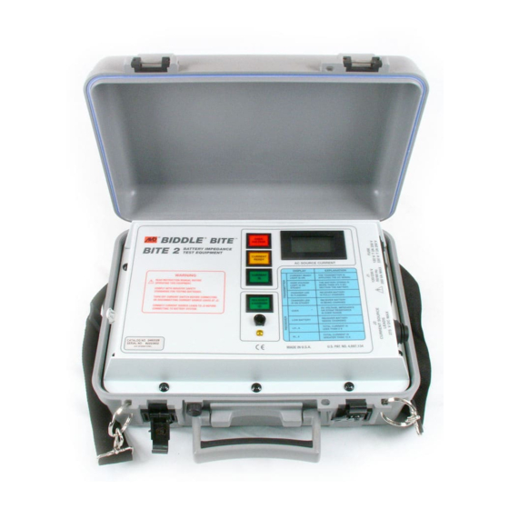
Page 18: Bite 2 Transmitter
BITE 2 Transmitter Figure 4-1 shows a front view of the BITE 2 transmitter. Over Voltage Current Ready Control Panel Current On/Off Switch Digital Meter Power Switch Receiver Charger On/Off Indicator Receiver Charger On/Off Indicator Figure 4-1: BITE 2 Transmitter Digital Meter—ac source current digital indicator with a... - Page 19 J2 connector—The transmitter current source leads are connected from this connector to the battery under test. J3 connector—The receiver battery is charged from this connector to J3 on the receiver to charge its battery. AVTM246004 BITE 2/2P Rev 13 June 2022...
-
Page 20: Bite 2P Transmitter
The power switch is marked with a | (for ON) and an O (for OFF). Current On/Off Switch—The current on/off switch is pressed to start or stop the flow of the test current to the battery. AVTM246004 BITE 2/2P Rev 13 June 2022... -
Page 21: Figure 4-3: Voltage Selector Card Orientation
J4 connector—The receiver battery is charged from the on the BITE 2P transmitter when the J4 connector on the transmitter is connected to the J3 connector on the receiver. AVTM246004 BITE 2/2P Rev 13 June 2022... -
Page 22: Receiver
Potential probe—The potential probe is used in conjunction with the receiver to take cell impedance, voltage, and strap resistance measurements. Trigger—The trigger is pulled to perform functions on the receiver, including entering test information. AVTM246004 BITE 2/2P Rev 13 June 2022... -
Page 23: Receiver Keys
These keys are also used to scroll up and down through receiver screens. The ENTER key is used to access receiver menus, which are shown in Figures 4-5 though 4-8. AVTM246004 BITE 2/2P Rev 13 June 2022... -
Page 24: Figure 4-5: Flowchart For Test Menu Structure-1
BASELINE MENU Y SPLIT STRAP? N (Y/N)? MENU + MULTIPLIER - > 1 < ACCEPT Y TERMINAL IMP N (Y/N)? MENU PWR2 SAVE SETTING? (Y/N)? MENU Figure 4-5: Flowchart for Test Menu Structure-1 AVTM246004 BITE 2/2P Rev 13 June 2022... -
Page 25: Figure 4-6: Flowchart For Test Menu Structure-2
CELL 003 xx.xx xx.xx STRAP xx.xx TEST Note 3 WARN TEST COMPLETE N (Y/N)? MENU Y ARE YOU SURE? N (Y/N)? MENU AVAILABLE CELL MEMORY XXXX Figure 4-6: Flowchart for Test Menu Structure-2 AVTM246004 BITE 2/2P Rev 13 June 2022... -
Page 26: Figure 4-7: Flowchart For Main Menu Structure
N (Y/N)? MENU Y ARE YOU SURE? N (Y/N)? MENU * 60Hz LINE FREQ 50Hz MENU Delete active test Delete oldest test AVAILABLE CELL MEMORY XXXX Figure 4-7: Flowchart for Main Menu Structure AVTM246004 BITE 2/2P Rev 13 June 2022... -
Page 27: Figure 4-8: Flowchart For Print Menu Structure
0 = CANCEL ACCEPT PRINTING… PRINTING… (print result) CANCEL (print all) CANCEL If test is closed If serial cable is removed and open test exists… resume cell test Figure 4-8: Flowchart for Print Menu Structure AVTM246004 BITE 2/2P Rev 13 June 2022... -
Page 28: Figure 4-9: Receiver Menu
1. Suppose that the following Menu is displayed on the screen as shown in Figure 4-9. 2. To select EXPORT DATA, press 3. However, to move from menu to menu, press Figure 4-9: Receiver Menu AVTM246004 BITE 2/2P Rev 13 June 2022... -
Page 29: Receiver Reset Switch
NOTE: If your receiver’s firmware is lower than 2.03 then do NOT use the RESET switch. It may result in permanent loss of data and loss of calibration. RESET Switch Figure 4-10: Receiver RESET Switch AVTM246004 BITE 2/2P Rev 13 June 2022... - Page 30 AVTM246004 BITE 2/2P Rev 13 June 2022...
-
Page 31: Standard Test Procedure
Chapter 2 “Safety”. The BITE 2/2P is used to test battery strings while the dc system is at float potential. It can store up to 2040 cell/jar records in up to 300 tests. The transmitter can provide test current for battery strings of up to 275 V dc. - Page 32 When using the BITE 2/2P, strictly observe all safety precautions. Operating Note The batteries must be in float mode to perform an ohmic test.
-
Page 33: Step One: Prepare For Testing
3. Record the cell temperature. 4. Record the ambient temperature. After you have successfully performed these pretest activities, you are ready to power on the receiver. The following subsection contains the appropriate procedures. AVTM246004 BITE 2/2P Rev 13 June 2022... -
Page 34: Step Two: Powering-On The Receiver
2. Connect the potential probe cable assembly to the 7-pin connector on the receiver. 3. Press the POWER ON switch on the receiver. The receiver powers on and displays several initialization screens. AVTM246004 BITE 2/2P Rev 13 June 2022... -
Page 35: Figure 5-2: Screens
After initializing, the receiver displays a screen that prompts you to decide whether you want to scan bar-coded information related to the test. The following subsection contains the appropriate procedures. AVTM246004 BITE 2/2P Rev 13 June 2022... -
Page 36: Step Three: Scanning Test Information With The Wand (Optional)
If you have a wand and you want to scan information about this test: The UP ARROW key 1. Press on the receiver. corresponds to the Y (for yes). The receiver prompts you to connect the wand. CONNECT WAND! AVTM246004 BITE 2/2P Rev 13 June 2022... -
Page 37: Figure 5-3: Scanning Test Information
DISCONNECT WAND: ..WAITING..7. Disconnect the wand from the 7-pin connector on the receiver. The receiver now prompts you to set baseline, warn and fail values for the test. AVTM246004 BITE 2/2P Rev 13 June 2022... -
Page 38: Step Four: Setting Baseline, Warning And Fail Values
Step Four: Setting Baseline, Warning and Fail Values The BITE 2/2P now lets you set baseline, warning and fail impedance values when conducting a test. Then, after displaying the cell or strap measurements, the BITE 2/2P receiver screen will indicate PASS, FAIL or WARN and will display the measured value as a percentage of the baseline value. -
Page 39: Step Five: Splitting The Strap (If Needed)
You are prompted to connect the CT to the strap. Proceed to “Step Seven: Connecting the Receiver and the BITE 2 or BITE 2P Transmitter to the Battery”. If You Want to Split... -
Page 40: Step Six: Terminal Impedance (If Needed)
2. The receiver screen asks if you want to save settings baseline, warn and fail values and the multiplier. SAVE SETTING? (Y/N) MENU Press (for YES) or for (NO). Proceed to Step Seven. AVTM246004 BITE 2/2P Rev 13 June 2022... -
Page 41: Step Seven: Connecting The Receiver And The Bite 2 Or Bite 2P Transmitter To The Battery
STANDARD TEST PROCEDURE Step Seven: Connecting the Receiver and the BITE 2 or BITE 2P Transmitter to the Battery WARNING! To avoid electric shock, always wear rubber gloves when making connection to battery systems. Voltages to ground in excess of 270 V dc are possible. -
Page 42: Figure 5-5: Bite 2/2P Transmitter Connected To The Battery
CONNECT & POWER TRANSMITTER: XX.X Source leads from To ac power transmitter connected to terminal plate Source leads from transmitter connected to terminal plate Black Figure 5-5: BITE 2/2P Transmitter Connected to the Battery AVTM246004 BITE 2/2P Rev 13 June 2022... - Page 43 CAUTION You can use the BITE 2 transmitter to provide test current for measurements on each cell/module for a battery string of up to 275 V dc. If the battery under test exceeds this limit, section the battery into portions that are less than 275 V dc.
-
Page 44: Step Eight: Measuring The Cell And The Strap
(Lo_A). This ensures proper current magnitude for accurate measurement since the total current includes both current from the BITE 2/2P and any ac ripple current produced by the battery charger. If significant ripple current is present and out of phase with the applied source current, a low current condition may occur. -
Page 45: Figure 5-6: Receiver And Potential Probe Positioned On Top Of Battery Cell Terminals
If you have entered baseline, warn and fail values, the screen will display either PASS, WARN or FAIL and a percentage of baseline. PASS AVTM246004 BITE 2/2P Rev 13 June 2022... -
Page 46: Figure 5-7: Receiver And Potential Probe Positioned On Top Of Battery Strap Terminals
The measurements are stored in the receiver. The receiver now displays the digits 002 in the top left corner of the test screen. This means that you are ready to test cell #2. AVTM246004 BITE 2/2P Rev 13 June 2022... - Page 47 The receiver displays a screen to indicate that the test is complete. DONE! For instructions on what to do following the test, see "Step Nine: What to Do When the Test Is Complete”. AVTM246004 BITE 2/2P Rev 13 June 2022...
- Page 48 If you have finished testing the first section of a sectioned battery string and want to measure the next section: 1. Press the Current ON/OFF switch on the BITE 2/2P transmitter. This blocks the current from being applied to the battery while the transmitter powers down.
-
Page 49: Step Nine: What To Do When The Test Is Complete
4. Start a new test. (Return to "Step One: Prepare for Testing". 5. Power down and disconnect the transmitter. You will need to do this if you are finished using the BITE 2/2P for this testing session. (See "Powering Down and Disconnecting the BITE 2/2P". - Page 50 J3. The LCD will display the following screen. (EXPORT DATA) TRANSMIT DATA (Y/N?) MENU 1. Press for TRANSMIT. The screen will display the following screen. EBITE/PC PRINTER MENU AVTM246004 BITE 2/2P Rev 13 June 2022...
-
Page 51: Powering Down And Disconnecting The Bite 2/2P
4. Reconnect the potential probe to resume testing. The measurement screen is displayed again. Powering Down and Disconnecting the BITE 2/2P Before you power down and disconnect the BITE 2/2P transmitter, first power down and disconnect the receiver. Then power down and disconnect the transmitter. Carefully follow these steps: 1. - Page 52 4. Disconnect the CT from the battery and the receiver. You can now power down the transmitter. 5. To power down the BITE 2/2P transmitter, press the Current ON/OFF switch to disconnect the current source. Then press the transmitter power switch to the O (OFF) position.
-
Page 53: Modified Procedures For Special Conditions
This chapter also describes optional equipment that can be used with the BITE 2 and BITE 2P test instruments. Reversing the Current Source Leads If the transmitter displays a high or low current message, you need to modify the test procedure. -
Page 54: Verifying The Source Current
To verify whether the magnitude of the source current is within the required limits (3-15 A): This temporarily “disconnects” 1. Press the Current switch on the BITE 2/2P transmitter the transmitter and blocks the to the O (OFF) position. -
Page 55: Sectioning A Battery System
(See "Sectioning a Battery System” below for the correct procedures.) Sectioning a Battery System To test certain battery systems with the BITE 2/2P, you must measure individual sections, one at a time. Examples are included in the following subsections. Sectioning a Battery... -
Page 56: Figure 6-2: Sectioning A Battery System Greater Than 275 V
O (OFF) position. If you have to move the transmitter to test the NOTE: next section, you may need to power down and disconnect the transmitter. (See "Powering Down and Disconnecting the BITE 2/2P". AVTM246004 BITE 2/2P Rev 13 June 2022... - Page 57 (not to exceed 275 V). WARNING Do not remove the BITE 2/2P transmitter current source leads from the battery until the BITE 2/2P transmitter current is de-energized. Always disconnect the current source leads from the battery before removing them from the J2 connector on the transmitter.
-
Page 58: Figure 6-3: Sectioning A Parallel String Of Cells
To test one of these systems, positions the current source leads accordingly to satisfy both the test current and the voltage limit of the BITE 2/2P. Refer to the procedure explained in the preceding subsection, "Sectioning a Battery System Greater than 275 Volts". - Page 59 MODIFIED PROCEDURES FOR SPECIAL CONDITIONS Sectioning Noisy UPS Systems The BITE 2/2P source current may be affected by the noise generated by the switching power supply or the inverter. In this situation, test only a few cells at a time. See Figure 6-2 and refer to the procedure explained earlier in the subsection, “Sectioning a Battery System Greater than 275...
- Page 60 AVTM246004 BITE 2/2P Rev 13 June 2022...
-
Page 61: Transferring, Printing, And Deleting Test Results
Delete test results from the receiver § When a test is completed using the BITE 2/2P, the results are automatically stored in the receiver. If needed the test results can be exported to a personal computer (PC) where it can then be viewed or printed. -
Page 62: Exporting Test Results From The Receiver To A Pc
1. Run the software on the PC that you are using to import the data. If needed, refer to the instruction manual that came with the software. Megger has shipped with the BITE 2/2P a software program called PowerDB. 2. Press the receiver Power On switch to energize the receiver. -
Page 63: Figure 7-1: Exporting Data To A Pc
A screen on the receiver tells you to wait as the test results are transferred. When the transfer is complete, the receiver prompts you to choose POWER DOWN or EXPORT DATA. POWER DOWN EXPORT DATA MENU AVTM246004 BITE 2/2P Rev 13 June 2022... -
Page 64: Printing Test Results In The Bite 2P Transmitter Printer
PC. 8. Turn off the power to the transmitter and receiver. (See "Powering Down and Disconnecting the BITE 2/2P". Printing Test Results in the BITE 2P Transmitter Printer To print test results on the built-in printer of the BITE 2P transmitter, connect the printer cable to the 7-pin connector on the receiver and to J3 on the BITE 2P transmitter. -
Page 65: Deleting Test Results From The Receiver
The receiver asks if you are sure you want to delete the data: ARE YOU SURE? (Y/N) MENU 3. Press on the receiver to enter Y (for YES). The test results are deleted and you are returned to Menu 1. AVTM246004 BITE 2/2P Rev 13 June 2022... -
Page 66: Figure 7-3: Deleting Test Results From The Receiver
Figure 7-3: Deleting Test Results from the Receiver AVTM246004 BITE 2/2P Rev 13 June 2022... -
Page 67: Interpreting Test Results
INTERPRETING TEST RESULTS Overview This chapter discusses various factors to consider when interpreting results of tests obtained with the BITE 2/BITE 2P. Impedance measurements with the BITE 2/2P should be made part of a battery maintenance program with readings taken and recorded semiannually for flooded lead-acid and nickel- cadmium cells and quarterly for VRLA. -
Page 68: Instantaneous Interpretation
Instantaneous Interpretation The BITE 2/2P receiver has the ability to calculate impedance deviations based on a preset baseline or benchmark value. On start-up (or after wanding) the following screen will appear: ENTER BASELINE? (Y/N) MENU To enter a baseline or benchmark value, press... -
Page 69: Short-Term Interpretation
In this case the cell may need to be reconditioned. Draining the capacity down and recharging it several times in order to generate enough heat to burn out the dendrites. AVTM246004 BITE 2/2P Rev 13 June 2022... -
Page 70: Figure 8-1: Generic Curve Of Impedance Vs. Cell Life
WEAK NORMAL active plate material. ABNORMAL % of Expected Battery Life Figure 8-1: Generic Curve of Impedance vs. Cell Life AVTM246004 BITE 2/2P Rev 13 June 2022... -
Page 71: Setting Options
BITE2/2P receiver. options to optimize the BITE 2 and BITE The BITE 2/2P receiver is shipped with certain options set, including: 2P functions for your use. Turning the backlight on and off so that the receiver screen §... -
Page 72: Adjusting The Receiver Screen Contrast
English is the default; however, you can easily select another language. 1. Press to access the receiver Menu 4. LANGUAGE SETTIME MENU 2. Press to select LANGUAGE. The first two language choices are displayed. ENGLISH FRANCAIS NEXT AVTM246004 BITE 2/2P Rev 13 June 2022... -
Page 73: Setting The Receiver Clock
15:15:00. 5. When you are finished setting the clock, press needed so that the minutes field is selected. Then press again. The receiver prompts you to save the new time and date. AVTM246004 BITE 2/2P Rev 13 June 2022... -
Page 74: Selecting The Line Frequency
To set the line frequency: 1. Press until the following screen appears. 2. Use to select the correct frequency. 3. Press MENU to exit the line frequency set-up. * 60 Hz LINE FREQ 50 Hz MENU AVTM246004 BITE 2/2P Rev 13 June 2022... -
Page 75: Maintenance And Troubleshooting
MAINTENANCE AND TROUBLESHOOTING Overview This chapter explains: How to maintain the BITE 2/2P so that it remains in § good operating condition How to interpret error messages § What to do if repairs are needed § NOTE: Before performing maintenance on the BITE 2... -
Page 76: Charging The Receiver
3. Connect the charger 3-pin input connector to J4 on 2 for the location of the receiver the transmitter at the charger panel. charger on the BITE 2 and BITE 2P transmitters. Refer to Figure 5-4 on for the 4. Connect the charger 3-pin output connector to the location of the 3-PIN connector. -
Page 77: Replacing Batteries In The Receiver
UK in accordance with Local their life. Authority requirements. For disposal of batteries in other parts of the EU contact your local distributor. Megger is registered in the UK as a producer of batteries. The Registration number is BPRN01235. - Page 78 Phillips head screws. 9. Snap the probe housing into place, and then fasten it using the two Phillips head screws. WARNING Make sure that no wires are pinched when replacing covers and housings!!!!! AVTM246004 BITE 2/2P Rev 13 June 2022...
-
Page 79: Figure 10-1: Rtc Battery "Piggybacks" The System Battery
Using a Phillips head screwdriver, remove the eight screws fastening the back cover and probe housing. 4. Carefully remove the probe housing. Remove the back cover. CAUTION Do not disturb the wrist strap, trigger assembly, or wiring harness. AVTM246004 BITE 2/2P Rev 13 June 2022... -
Page 80: Maintaining The Receiver Charger In The Bite 2 And Bite 2P
Make sure that no wires are pinched when replacing covers and housings!!!!! Maintaining the Receiver Charger in the BITE 2 and BITE 2P NOTE: The charger in the BITE 2P transmitter does not have a user-replaceable fuse. Please call Megger at 610-676-8500 (or email to battery@megger.com) if... -
Page 81: Maintaining Fuses In The Bite 2 And Bite 2P Transmitters
Replaceable Parts. Verifying a Transmitter Fuse Problem If you encounter a problem with the BITE 2 or BITE 2P transmitter, check the primary and secondary fuses to see if the problem is fuse related. AVTM246004 BITE 2/2P Rev 13 June 2022... - Page 82 CURRENT READY indicator. If neither indication occurs, the primary fuse may be bad. Refer to the appropriate subsection, "Replacing Fuses in the BITE 2 Transmitter" or "Replacing Fuses in the BITE 2P Transmitter". Identifying a...
- Page 83 Replacing the BITE 2 Transmitter Primary Fuse To replace the BITE 2 transmitter primary fuse: 1. Remove the transmitter from the vicinity of the battery room. 2. Press the transmitter power switch to the O (OFF) position. Then disconnect the ac power cord from the ac outlet.
- Page 84 WARNING Do not remove the BITE 2 transmitter current source leads from the battery until the BITE 2 transmitter is powered down. Always disconnect the current source leads from the battery before removing them from the J2 connector on the transmitter.
-
Page 85: Figure 10-2: Bite 2 Transmitter Secondary Fuses (Front View)
Replacing the BITE 2 Transmitter Secondary Fuses Fuse Location Figure 10-2: BITE 2 Transmitter Secondary Fuses (front view) To replace the transmitter secondary fuses: 1. Remove the transmitter from the vicinity of the battery room. 2. Press the transmitter power switch to the O (OFF position to power down the transmitter. - Page 86 "Verifying a Transmitter Fuse Problem". 9. Replace the top panel screws. If the instrument still does not respond correctly, return it to Megger for service. Please refer to "If the BITE 2 or BITE 2P Needs Repairs". WARNING Under no circumstances should any fuse be defeated or replaced with another type of fuse.
- Page 87 “Verifying a Transmitter Fuse Problem.” If the instrument still does not respond correctly, return it to Megger for service. Please refer to "If the BITE 2 or BITE 2P Needs Repairs" for the necessary information. AVTM246004 BITE 2/2P Rev 13 June 2022...
-
Page 88: Figure 10-3: Bite 2P Transmitter Secondary Fuses (Front View)
(see Figure 10-3 shown earlier in this chapter). The fuses should be marked 15 ATM or 15 KLM. 6. Remove the fuses from the fuse block. Verify if one or both fuses are bad. AVTM246004 BITE 2/2P Rev 13 June 2022... - Page 89 "Verifying a Transmitter Fuse Problem". If the instrument still does not respond correctly, return it to Megger for service. Please refer to "If the BITE 2 or BITE 2P Needs Repairs" for the necessary information. AVTM246004 BITE 2/2P Rev 13 June 2022...
-
Page 90: Interpreting Error Messages
275 Vdc. Section the battery as described under "Sectioning a Battery System". If the BITE 2 or BITE 2P Needs Repairs Megger offers complete repair service and recommends that its customers take advantage of this service in the event of equipment malfunction. -
Page 91: Specifications
SPECIFICATIONS Application The BITE 2/2P can test lead-acid and nickel-cadmium cells of less than 7000 Ah capacity. Tests on most battery systems require the standard clamp-on current sensor (CT) with a 2-inch opening. Maximum total voltage at BITE2/2P transmitter current source connections is 275 V dc (larger battery systems can be sectioned to accommodate this specification). - Page 92 100 µΩ Ripple Current: Range: 100mA -15A, plus CT Supply: 4.8 V dc, 800 mAh, quick-charge NiMH battery pack Battery Pack Life, Full Charge: 5 hours continuous Maximum Voltage Between Potential Probes: 25V dc AVTM246004 BITE 2/2P Rev 13 June 2022...
-
Page 93: Mechanical
2.19 in. (55.7 mm) x 0.43 in. (11 mm) viewing area, displays measured parameters in dark numbers on an electroluminescent background. Contrast adjustable from menu selection Commercial temperature and humidity ranges for the LCD will limit the useful measurement environment. AVTM246004 BITE 2/2P Rev 13 June 2022... -
Page 94: Environmental
Charging temperature range to 50 to 95°F (10 to 35°C) Ingress Protection Rating 246002B BITE2 Lid Closed IP67 246002B BITE2 Lid Open IP50 246004 BITE2P Lid Closed IP67 246004 BITE2P Lid Open IP30 AVTM246004 BITE 2/2P Rev 13 June 2022... -
Page 95: Accessories - Standard
CT Extension cable: for clamp-on current sensor (CT). § Wire rating 300 V Length: 6 ft (1.8 m) Termination: Nonmetallic push lock 7 pin, both ends Accessory bag: for receiver, charger and test leads. (BITE 2) § AVTM246004 BITE 2/2P Rev 13 June 2022... - Page 96 Communication cable: interconnects receiver to § transmitter or personal computer serial port. Wire rating 300 V dc Length: 6 ft (1.8 m) Termination (receiver): Nonmetallic push lock 7-pin Termination (computer): Receptacle 9-pin AVTM246004 BITE 2/2P Rev 13 June 2022...
-
Page 97: Replaceable Parts
Secondary fuses, 15 ATM, 60 V, 10.3 x 38.1 mm 29440-1 Spare battery pack (receiver), NiMH, 800 mAh 30654 RTC battery 35569 ProActivÔ – Database Management Tool BI-90001 Instruction manual, BITE 2-2P AVTM246004 Canvas accessory bag (BITE 2) 29996 AVTM246004 BITE 2/2P Rev 13 June 2022... -
Page 98: Catalog Numbers 246002B And 246004
Canvas carrying case, instrument 218746 Thermal printer paper 26999 How to Order Replaceable Parts for the BITE 2/2P To order one or more replaceable parts for the BITE 2P, call 1-610-676-8500. Ask for Customer Service. AVTM246004 BITE 2/2P Rev 13 June 2022...
Need help?
Do you have a question about the BITE 2 and is the answer not in the manual?
Questions and answers